Technical Information · issue 43 of 2005
New hedge trimmers STIHL HS 81, HS 86
Model Complete machine
IssueTI 43/2005
Full text
Page 1 of 14
Text of page 1 — search, copy, screen readers
STIH)

Technical Information                                  43.2005

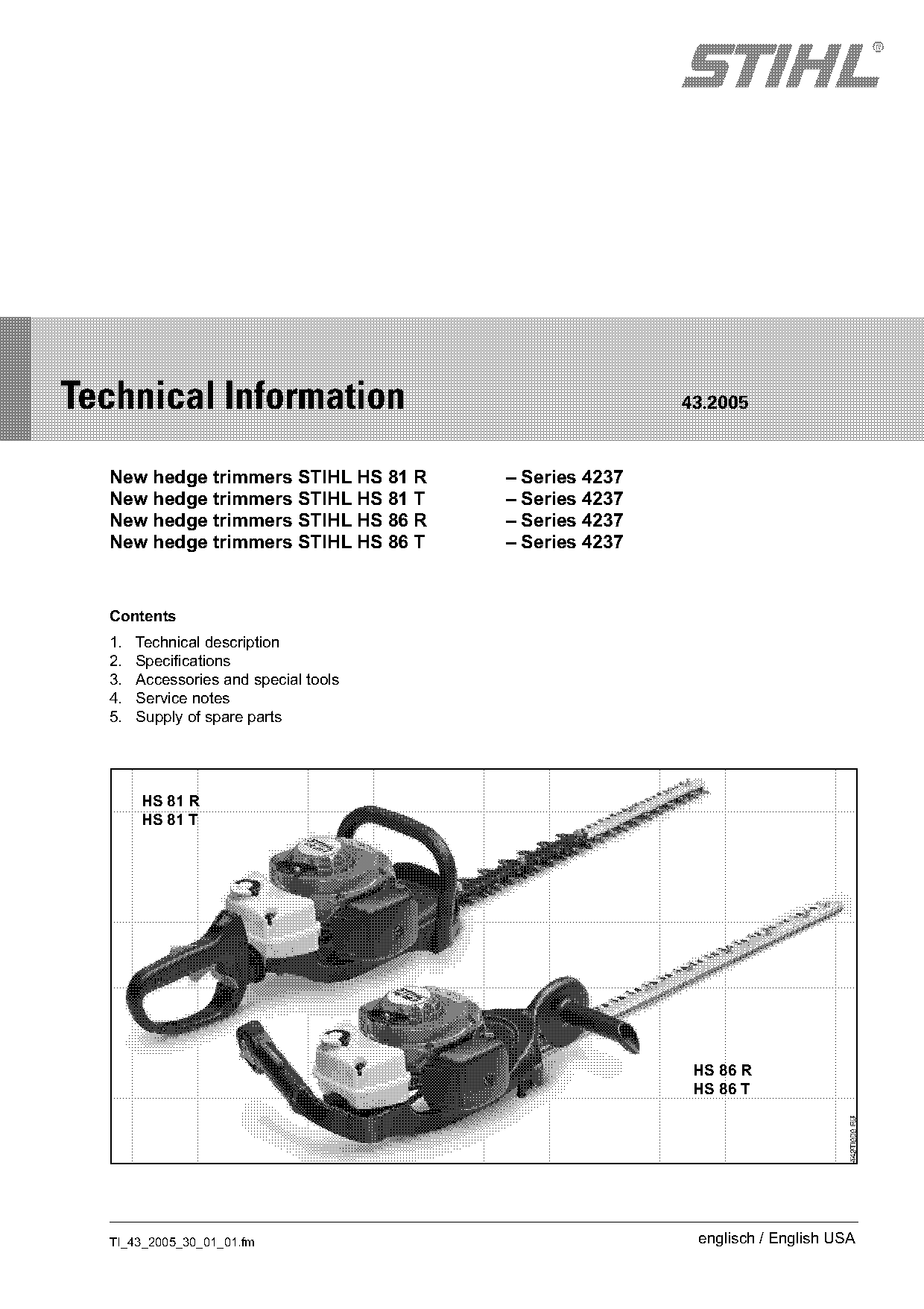
  New hedge trimmers STIHL HS 81 R     – Series 4237
  New hedge trimmers STIHL HS 81 T     – Series 4237
  New hedge trimmers STIHL HS 86 R     – Series 4237
  New hedge trimmers STIHL HS 86 T     – Series 4237

  Contents
  1.   Technical description
  2.   Specifications
  3.   Accessories and special tools
  4.   Service notes
  5.   Supply of spare parts

       HS 81 R
       HS 81 T

                                                        HS 86 R
                                                        HS 86 T

  TI_43_2005_30_01_01.fm                                englisch / English USA
Page 2 of 14
Text of page 2 — search, copy, screen readers
Page 2                                                Technical Information 43.2005

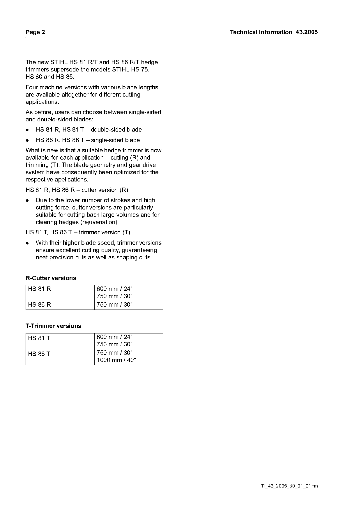
The new STIHL HS 81 R/T and HS 86 R/T hedge
trimmers supersede the models STIHL HS 75,
HS 80 and HS 85.
Four machine versions with various blade lengths
are available altogether for different cutting
applications.
As before, users can choose between single-sided
and double-sided blades:
.   HS 81 R, HS 81 T – double-sided blade
.   HS 86 R, HS 86 T – single-sided blade
What is new is that a suitable hedge trimmer is now
available for each application – cutting (R) and
trimming (T). The blade geometry and gear drive
system have consequently been optimized for the
respective applications.
HS 81 R, HS 86 R – cutter version (R):
.   Due to the lower number of strokes and high
    cutting force, cutter versions are particularly
    suitable for cutting back large volumes and for
    clearing hedges (rejuvenation)
HS 81 T, HS 86 T – trimmer version (T):
.   With their higher blade speed, trimmer versions
    ensure excellent cutting quality, guaranteeing
    neat precision cuts as well as shaping cuts

R-Cutter versions
HS 81 R                    600 mm / 24"
                           750 mm / 30"
HS 86 R                    750 mm / 30"

T-Trimmer versions

HS 81 T                    600 mm / 24"
                           750 mm / 30"
HS 86 T                    750 mm / 30"
                           1000 mm / 40"

                                                                TI_43_2005_30_01_01.fm
Page 3 of 14
Text of page 3 — search, copy, screen readers
Technical Information 43.2005                                                                     Page 3

1.       Technical description

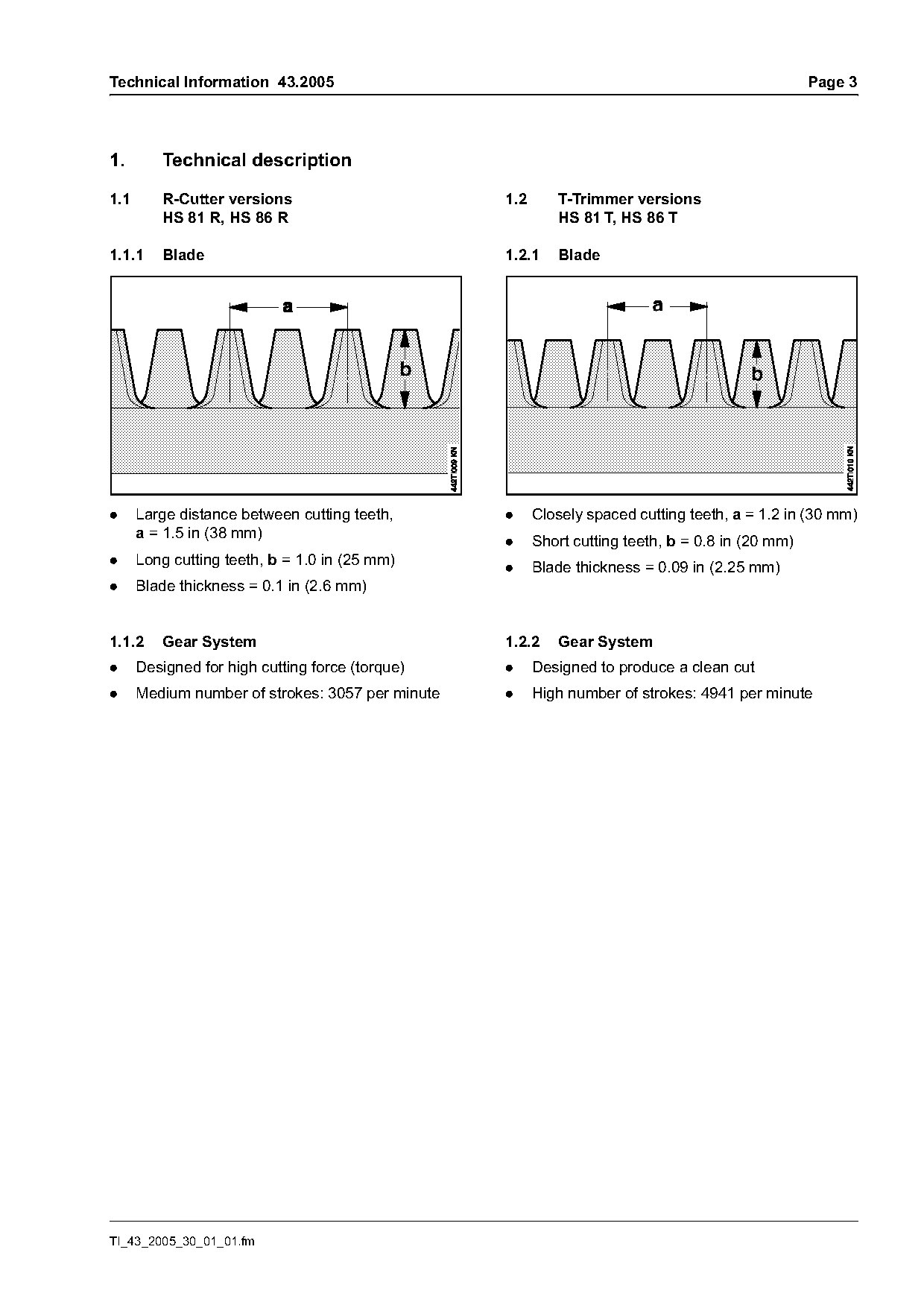
1.1      R-Cutter versions                        1.2      T-Trimmer versions
         HS 81 R, HS 86 R                                  HS 81 T, HS 86 T

1.1.1    Blade                                    1.2.1    Blade

.     Large distance between cutting teeth,       .     Closely spaced cutting teeth, a = 1.2 in (30 mm)
      a = 1.5 in (38 mm)                          .     Short cutting teeth, b = 0.8 in (20 mm)
.     Long cutting teeth, b = 1.0 in (25 mm)
                                                  .     Blade thickness = 0.09 in (2.25 mm)
.     Blade thickness = 0.1 in (2.6 mm)

1.1.2    Gear System                              1.2.2    Gear System
.     Designed for high cutting force (torque)    .     Designed to produce a clean cut
.     Medium number of strokes: 3057 per minute   .     High number of strokes: 4941 per minute

TI_43_2005_30_01_01.fm
Page 4 of 14
Text of page 4 — search, copy, screen readers
Page 4                                                                      Technical Information 43.2005

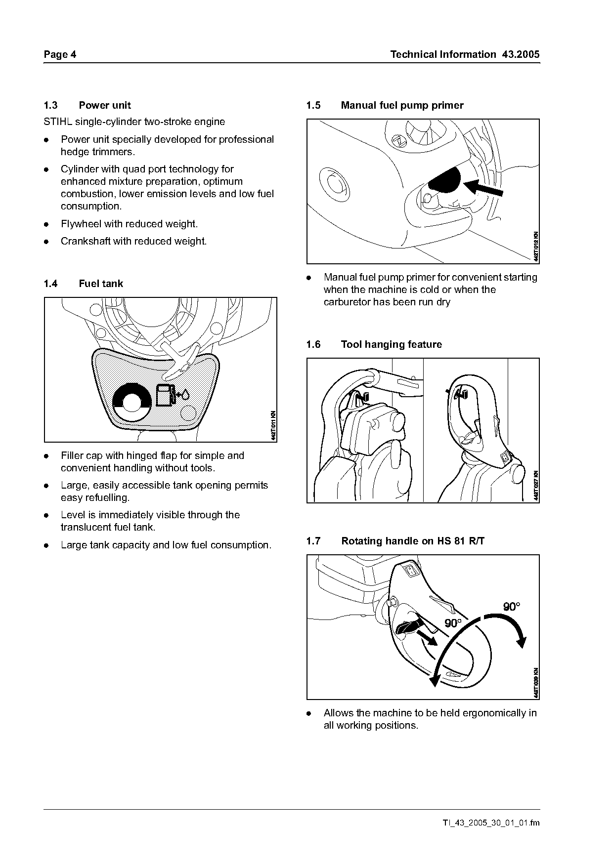
1.3       Power unit                                    1.5      Manual fuel pump primer
STIHL single-cylinder two-stroke engine
.     Power unit specially developed for professional
      hedge trimmers.
.     Cylinder with quad port technology for
      enhanced mixture preparation, optimum
      combustion, lower emission levels and low fuel
      consumption.
.     Flywheel with reduced weight.
.     Crankshaft with reduced weight.

                                                        .     Manual fuel pump primer for convenient starting
1.4       Fuel tank
                                                              when the machine is cold or when the
                                                              carburetor has been run dry

                                                        1.6      Tool hanging feature

.     Filler cap with hinged flap for simple and
      convenient handling without tools.
.     Large, easily accessible tank opening permits
      easy refuelling.
.     Level is immediately visible through the
      translucent fuel tank.
.     Large tank capacity and low fuel consumption.     1.7      Rotating handle on HS 81 R/T

                                                        .     Allows the machine to be held ergonomically in
                                                              all working positions.

                                                                                        TI_43_2005_30_01_01.fm
Page 5 of 14
Text of page 5 — search, copy, screen readers
Technical Information 43.2005                                                                   Page 5

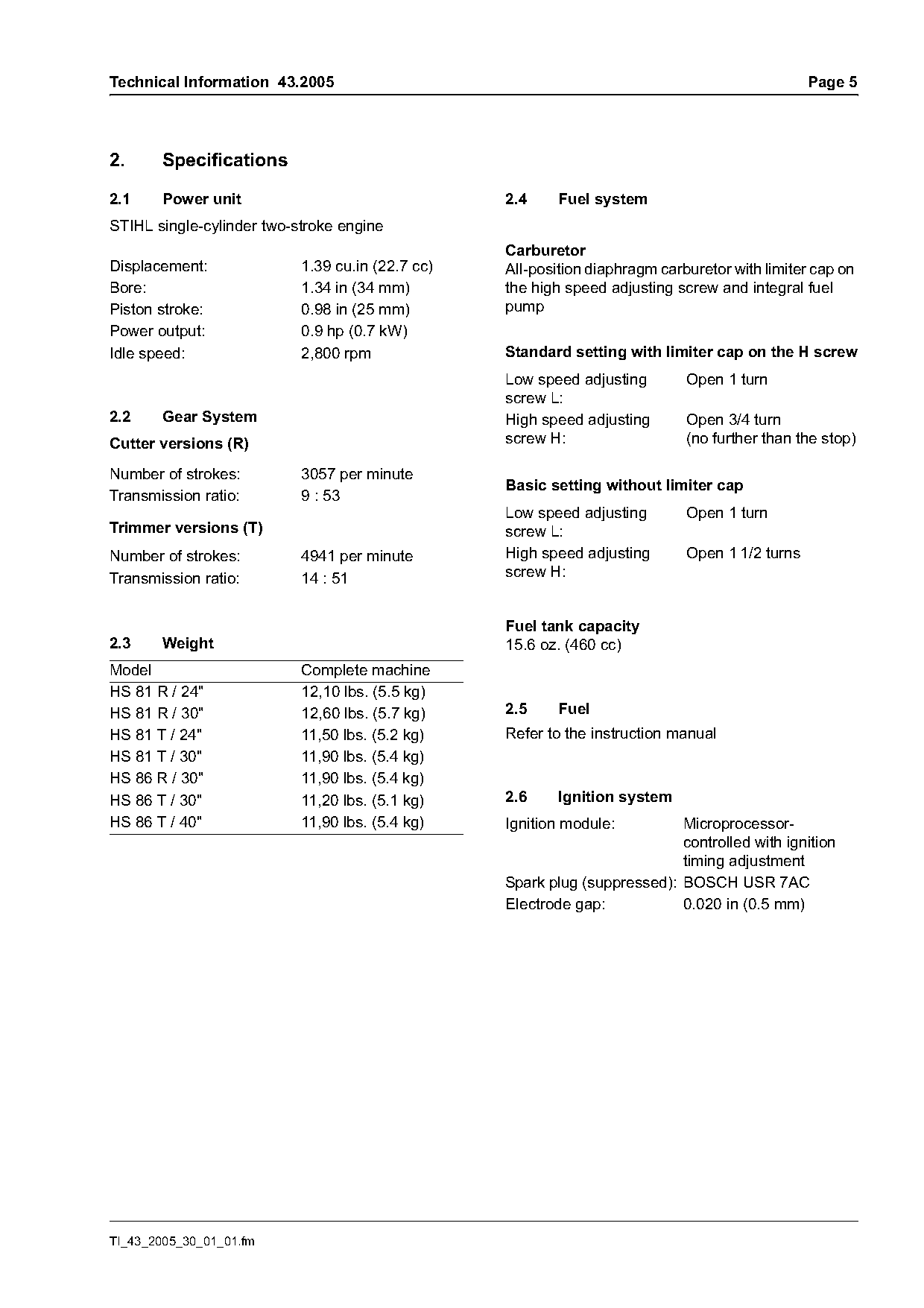
2.     Specifications

2.1    Power unit                                 2.4     Fuel system
STIHL single-cylinder two-stroke engine
                                                  Carburetor
Displacement:              1.39 cu.in (22.7 cc)   All-position diaphragm carburetor with limiter cap on
Bore:                      1.34 in (34 mm)        the high speed adjusting screw and integral fuel
Piston stroke:             0.98 in (25 mm)        pump
Power output:              0.9 hp (0.7 kW)
Idle speed:                2,800 rpm              Standard setting with limiter cap on the H screw
                                                  Low speed adjusting        Open 1 turn
                                                  screw L:
2.2    Gear System                                High speed adjusting       Open 3/4 turn
Cutter versions (R)                               screw H:                   (no further than the stop)

Number of strokes:         3057 per minute
                                                  Basic setting without limiter cap
Transmission ratio:        9 : 53
                                                  Low speed adjusting        Open 1 turn
Trimmer versions (T)                              screw L:
Number of strokes:         4941 per minute        High speed adjusting       Open 1 1/2 turns
Transmission ratio:        14 : 51                screw H:

                                                  Fuel tank capacity
2.3    Weight                                     15.6 oz. (460 cc)
Model                      Complete machine
HS 81 R / 24"              12,10 lbs. (5.5 kg)
HS 81 R / 30"              12,60 lbs. (5.7 kg)    2.5     Fuel
HS 81 T / 24"              11,50 lbs. (5.2 kg)    Refer to the instruction manual
HS 81 T / 30"              11,90 lbs. (5.4 kg)
HS 86 R / 30"              11,90 lbs. (5.4 kg)
HS 86 T / 30"              11,20 lbs. (5.1 kg)    2.6     Ignition system
HS 86 T / 40"              11,90 lbs. (5.4 kg)    Ignition module:         Microprocessor-
                                                                           controlled with ignition
                                                                           timing adjustment
                                                  Spark plug (suppressed): BOSCH USR 7AC
                                                  Electrode gap:           0.020 in (0.5 mm)

TI_43_2005_30_01_01.fm
Page 6 of 14
Text of page 6 — search, copy, screen readers
Page 6                                                                   Technical Information 43.2005

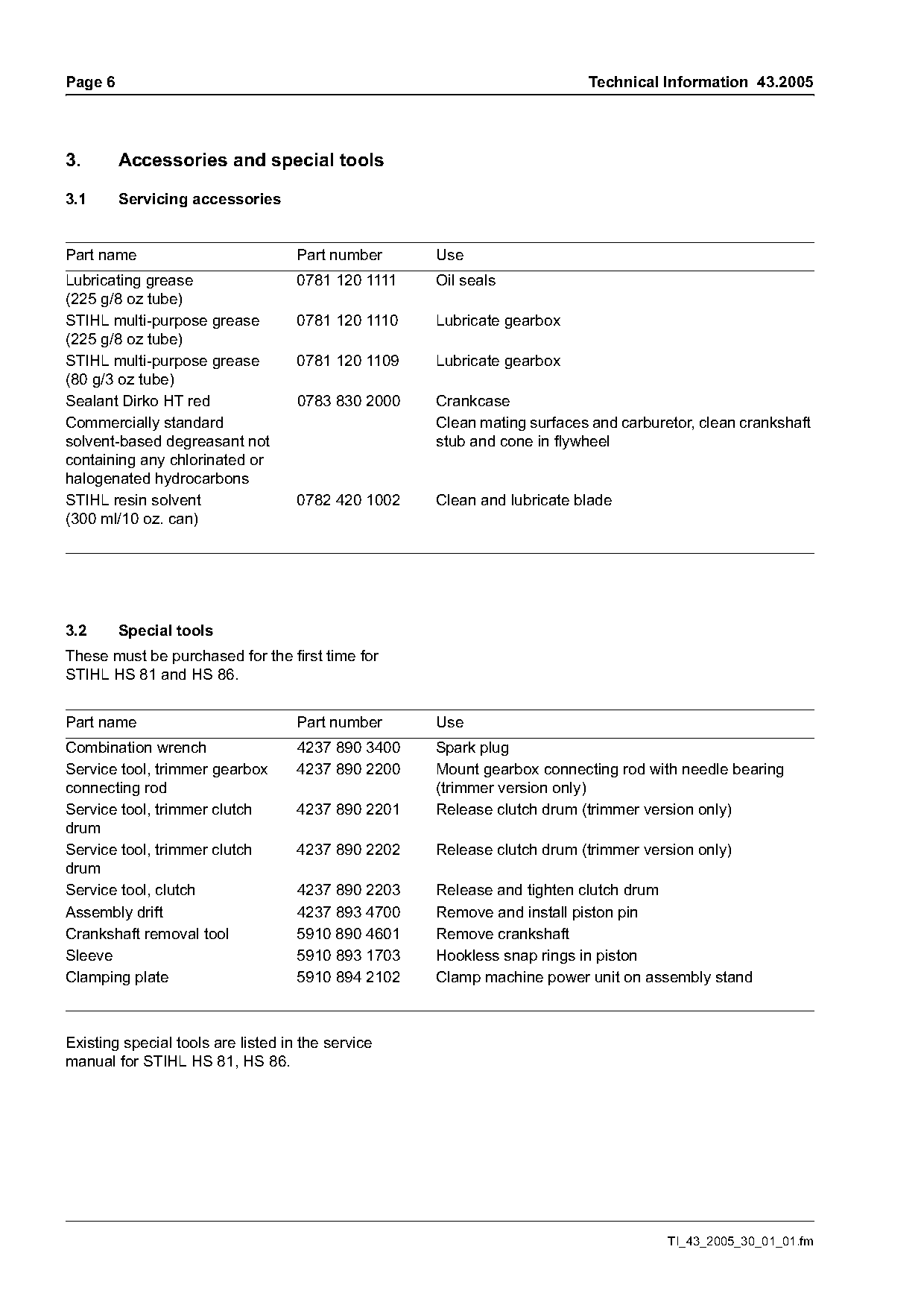
3.       Accessories and special tools

3.1      Servicing accessories

Part name                           Part number     Use
Lubricating grease                  0781 120 1111   Oil seals
(225 g/8 oz tube)
STIHL multi-purpose grease          0781 120 1110   Lubricate gearbox
(225 g/8 oz tube)
STIHL multi-purpose grease          0781 120 1109   Lubricate gearbox
(80 g/3 oz tube)
Sealant Dirko HT red                0783 830 2000   Crankcase
Commercially standard                               Clean mating surfaces and carburetor, clean crankshaft
solvent-based degreasant not                        stub and cone in flywheel
containing any chlorinated or
halogenated hydrocarbons
STIHL resin solvent                 0782 420 1002   Clean and lubricate blade
(300 ml/10 oz. can)

3.2      Special tools
These must be purchased for the first time for
STIHL HS 81 and HS 86.

Part name                           Part number     Use
Combination wrench                  4237 890 3400   Spark plug
Service tool, trimmer gearbox       4237 890 2200   Mount gearbox connecting rod with needle bearing
connecting rod                                      (trimmer version only)
Service tool, trimmer clutch        4237 890 2201   Release clutch drum (trimmer version only)
drum
Service tool, trimmer clutch        4237 890 2202   Release clutch drum (trimmer version only)
drum
Service tool, clutch                4237 890 2203   Release and tighten clutch drum
Assembly drift                      4237 893 4700   Remove and install piston pin
Crankshaft removal tool             5910 890 4601   Remove crankshaft
Sleeve                              5910 893 1703   Hookless snap rings in piston
Clamping plate                      5910 894 2102   Clamp machine power unit on assembly stand

Existing special tools are listed in the service
manual for STIHL HS 81, HS 86.

                                                                                     TI_43_2005_30_01_01.fm
Page 7 of 14
Text of page 7 — search, copy, screen readers
Technical Information 43.2005                                                                     Page 7

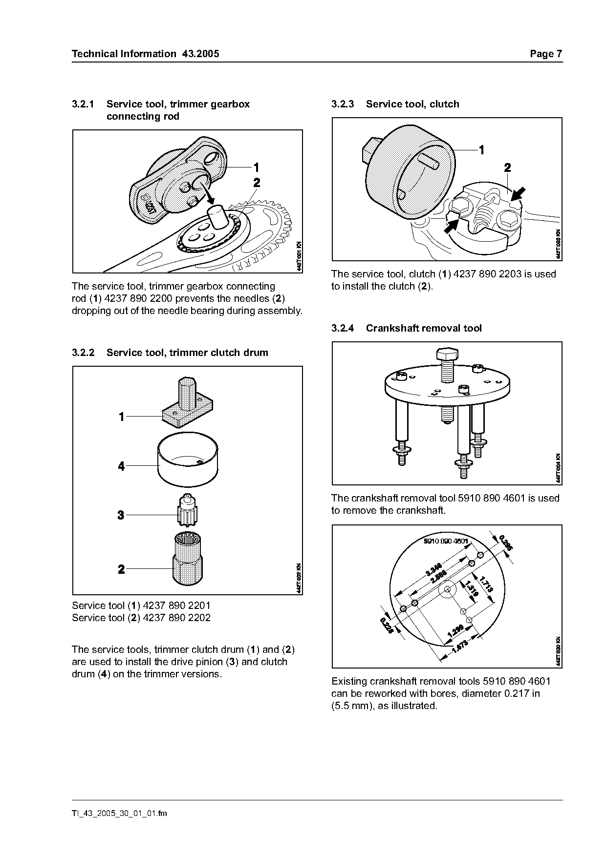
3.2.1   Service tool, trimmer gearbox                 3.2.3   Service tool, clutch
        connecting rod

                                                      The service tool, clutch (1) 4237 890 2203 is used
The service tool, trimmer gearbox connecting          to install the clutch (2).
rod (1) 4237 890 2200 prevents the needles (2)
dropping out of the needle bearing during assembly.
                                                      3.2.4   Crankshaft removal tool

3.2.2   Service tool, trimmer clutch drum

                                                      The crankshaft removal tool 5910 890 4601 is used
                                                      to remove the crankshaft.

Service tool (1) 4237 890 2201
Service tool (2) 4237 890 2202

The service tools, trimmer clutch drum (1) and (2)
are used to install the drive pinion (3) and clutch
drum (4) on the trimmer versions.
                                                      Existing crankshaft removal tools 5910 890 4601
                                                      can be reworked with bores, diameter 0.217 in
                                                      (5.5 mm), as illustrated.

TI_43_2005_30_01_01.fm
Page 8 of 14
Text of page 8 — search, copy, screen readers
Page 8                                                                      Technical Information 43.2005

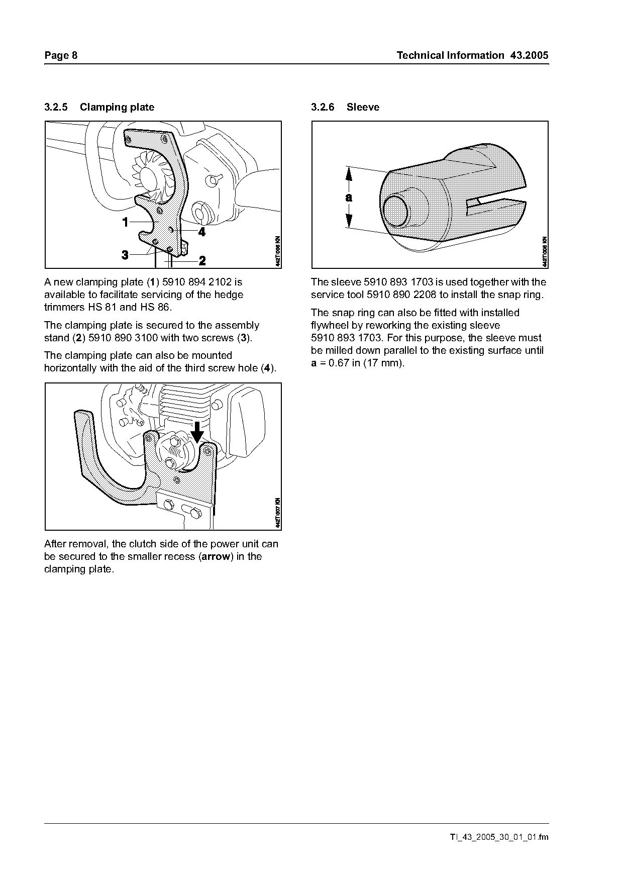
3.2.5    Clamping plate                                  3.2.6   Sleeve

A new clamping plate (1) 5910 894 2102 is                The sleeve 5910 893 1703 is used together with the
available to facilitate servicing of the hedge           service tool 5910 890 2208 to install the snap ring.
trimmers HS 81 and HS 86.                                The snap ring can also be fitted with installed
The clamping plate is secured to the assembly            flywheel by reworking the existing sleeve
stand (2) 5910 890 3100 with two screws (3).             5910 893 1703. For this purpose, the sleeve must
                                                         be milled down parallel to the existing surface until
The clamping plate can also be mounted
                                                         a = 0.67 in (17 mm).
horizontally with the aid of the third screw hole (4).

After removal, the clutch side of the power unit can
be secured to the smaller recess (arrow) in the
clamping plate.

                                                                                        TI_43_2005_30_01_01.fm
Page 9 of 14
Text of page 9 — search, copy, screen readers
Technical Information 43.2005                                                                    Page 9

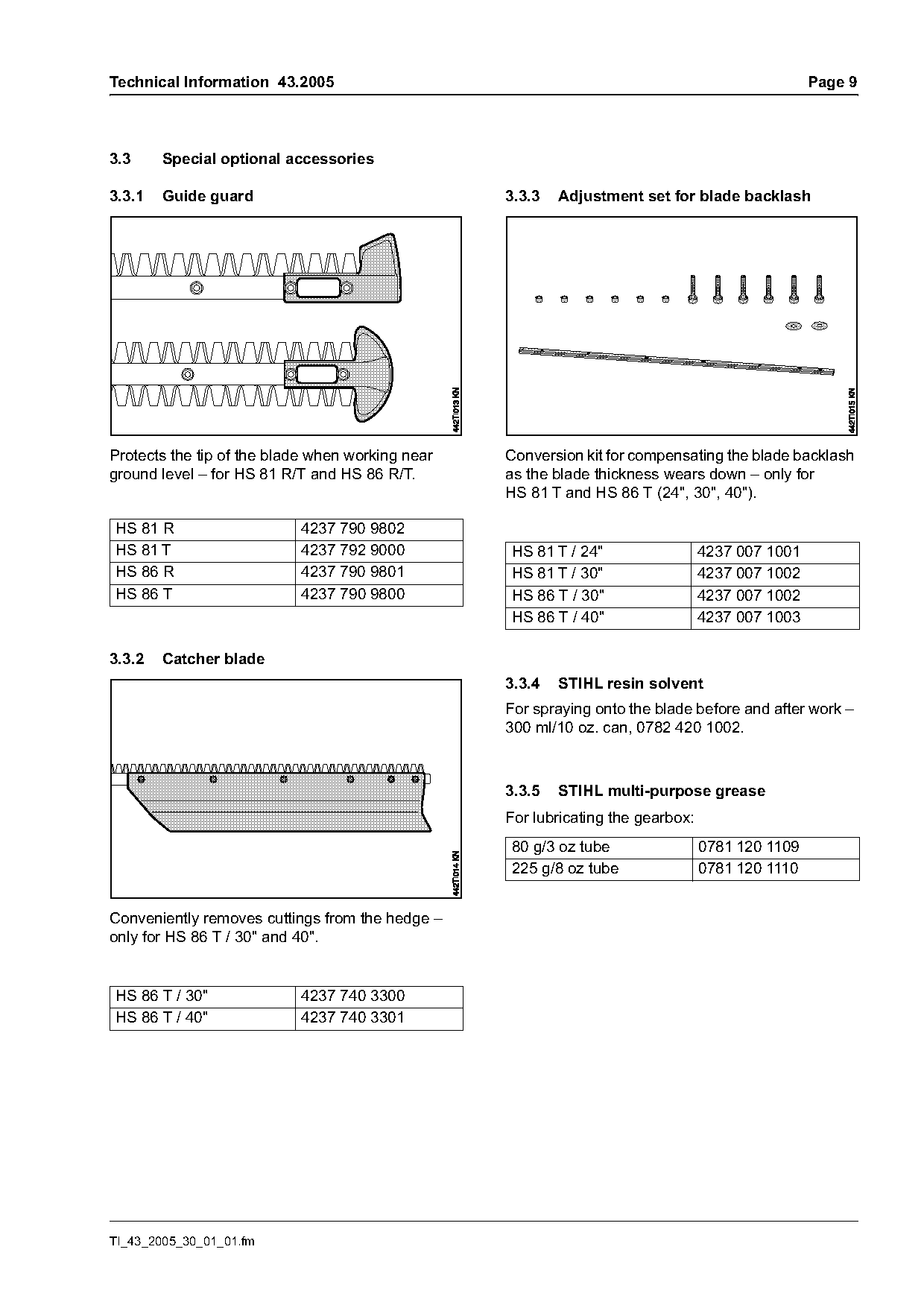
3.3     Special optional accessories

3.3.1   Guide guard                               3.3.3   Adjustment set for blade backlash

Protects the tip of the blade when working near   Conversion kit for compensating the blade backlash
ground level – for HS 81 R/T and HS 86 R/T.       as the blade thickness wears down – only for
                                                  HS 81 T and HS 86 T (24", 30", 40").

HS 81 R                    4237 790 9802
HS 81 T                    4237 792 9000          HS 81 T / 24"                  4237 007 1001
HS 86 R                    4237 790 9801          HS 81 T / 30"                  4237 007 1002
HS 86 T                    4237 790 9800          HS 86 T / 30"                  4237 007 1002
                                                  HS 86 T / 40"                  4237 007 1003

3.3.2   Catcher blade
                                                  3.3.4   STIHL resin solvent
                                                  For spraying onto the blade before and after work –
                                                  300 ml/10 oz. can, 0782 420 1002.

                                                  3.3.5   STIHL multi-purpose grease
                                                  For lubricating the gearbox:
                                                  80 g/3 oz tube                 0781 120 1109
                                                  225 g/8 oz tube                0781 120 1110

Conveniently removes cuttings from the hedge –
only for HS 86 T / 30" and 40".

HS 86 T / 30"              4237 740 3300
HS 86 T / 40"              4237 740 3301

TI_43_2005_30_01_01.fm
Page 10 of 14
Text of page 10 — search, copy, screen readers
Page 10                                                                  Technical Information 43.2005

4.      Service notes

4.1     Differences T/R

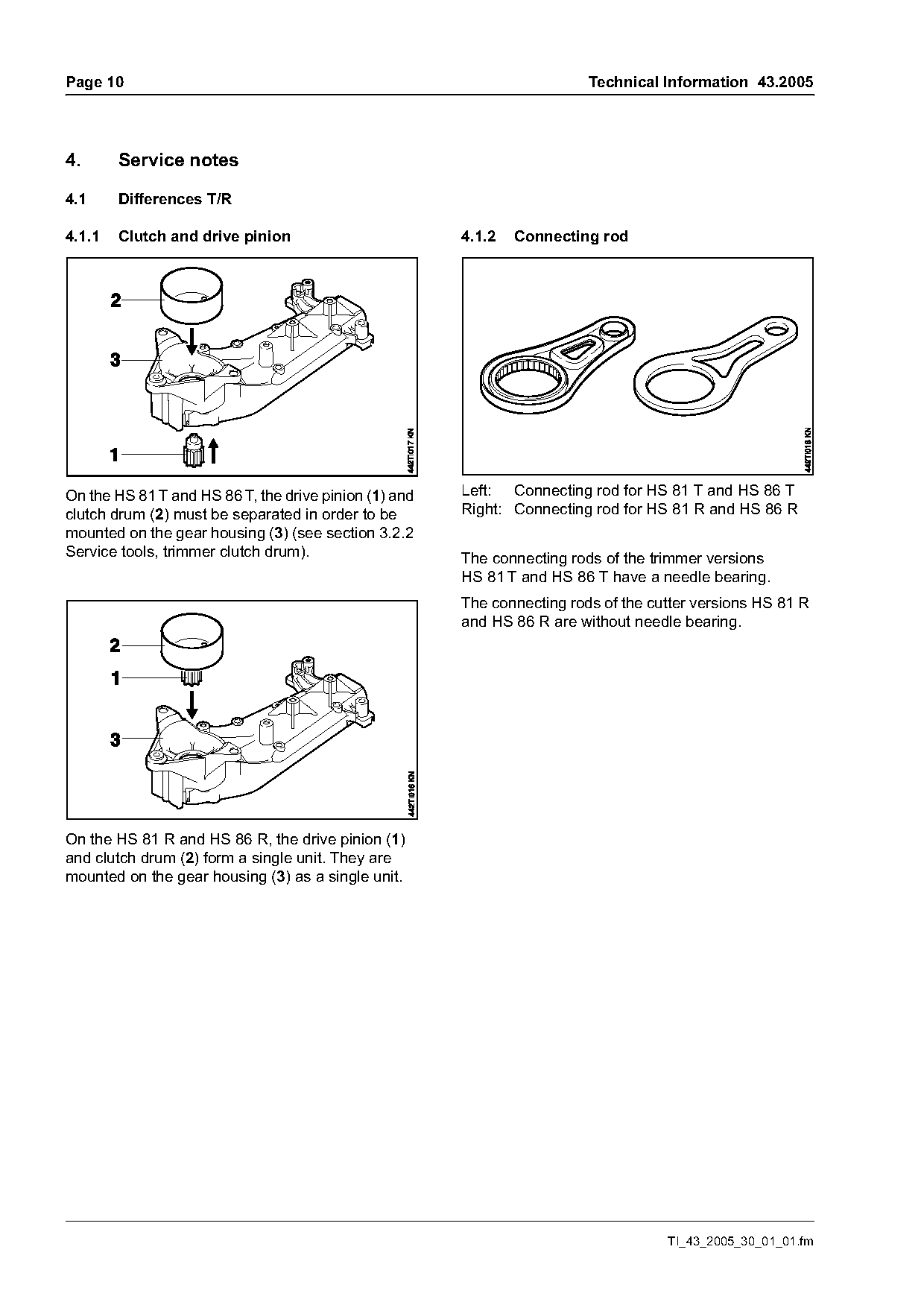
4.1.1   Clutch and drive pinion                        4.1.2   Connecting rod

On the HS 81 T and HS 86 T, the drive pinion (1) and   Left: Connecting rod for HS 81 T and HS 86 T
clutch drum (2) must be separated in order to be       Right: Connecting rod for HS 81 R and HS 86 R
mounted on the gear housing (3) (see section 3.2.2
Service tools, trimmer clutch drum).                   The connecting rods of the trimmer versions
                                                       HS 81 T and HS 86 T have a needle bearing.
                                                       The connecting rods of the cutter versions HS 81 R
                                                       and HS 86 R are without needle bearing.

On the HS 81 R and HS 86 R, the drive pinion (1)
and clutch drum (2) form a single unit. They are
mounted on the gear housing (3) as a single unit.

                                                                                    TI_43_2005_30_01_01.fm
Page 11 of 14
Text of page 11 — search, copy, screen readers
Technical Information 43.2005                                                                         Page 11

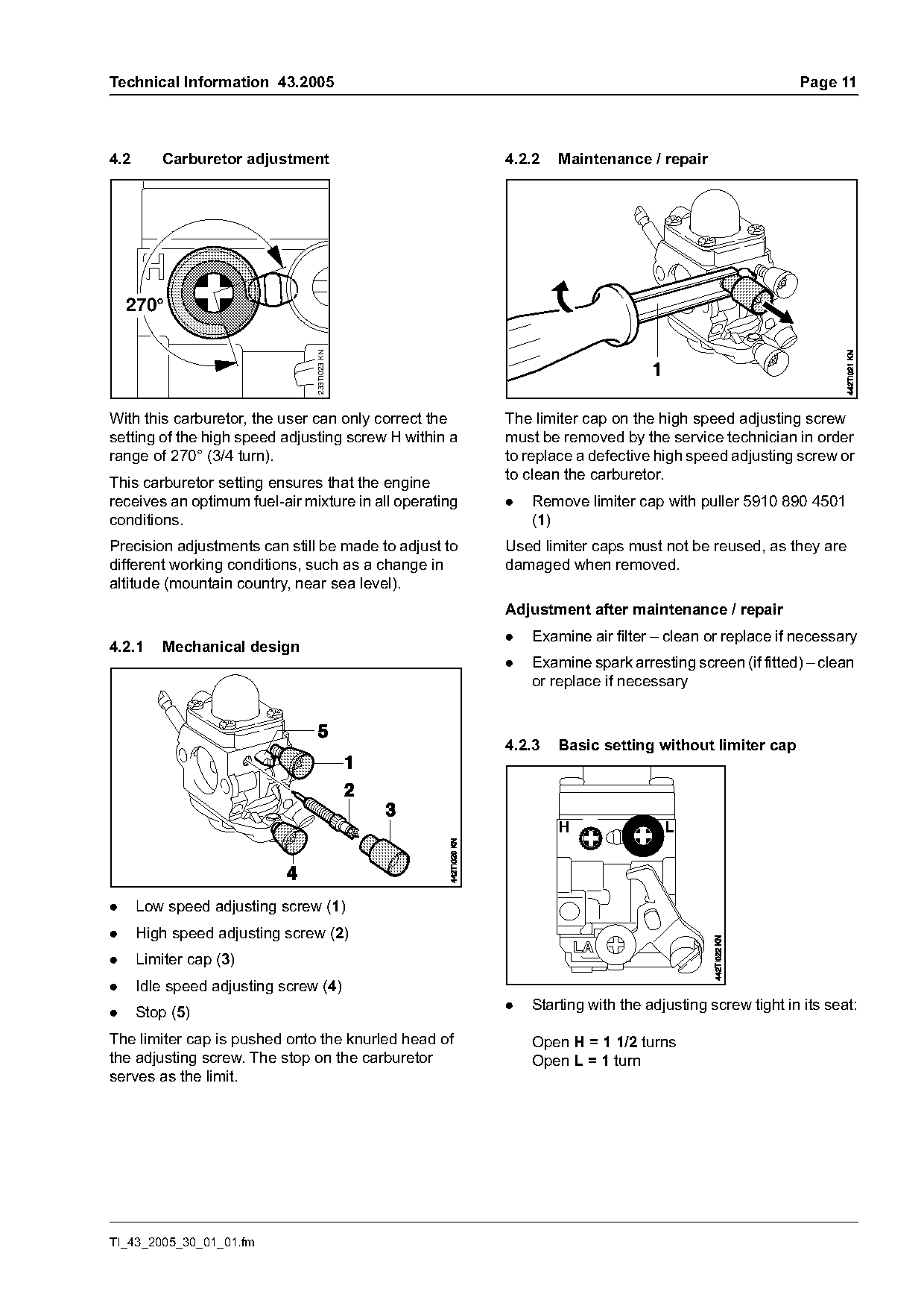
4.2       Carburetor adjustment                         4.2.2   Maintenance / repair

    270°
                                233TI023 KN

With this carburetor, the user can only correct the     The limiter cap on the high speed adjusting screw
setting of the high speed adjusting screw H within a    must be removed by the service technician in order
range of 270° (3/4 turn).                               to replace a defective high speed adjusting screw or
                                                        to clean the carburetor.
This carburetor setting ensures that the engine
receives an optimum fuel-air mixture in all operating   .   Remove limiter cap with puller 5910 890 4501
conditions.                                                 (1)
Precision adjustments can still be made to adjust to    Used limiter caps must not be reused, as they are
different working conditions, such as a change in       damaged when removed.
altitude (mountain country, near sea level).
                                                        Adjustment after maintenance / repair
                                                        .   Examine air filter – clean or replace if necessary
4.2.1     Mechanical design
                                                        .   Examine spark arresting screen (if fitted) – clean
                                                            or replace if necessary

                                                        4.2.3   Basic setting without limiter cap

                                                                H                L

.     Low speed adjusting screw (1)
.     High speed adjusting screw (2)
.     Limiter cap (3)
.     Idle speed adjusting screw (4)
                                                        .   Starting with the adjusting screw tight in its seat:
.     Stop (5)
The limiter cap is pushed onto the knurled head of          Open H = 1 1/2 turns
the adjusting screw. The stop on the carburetor             Open L = 1 turn
serves as the limit.

TI_43_2005_30_01_01.fm
Page 12 of 14
Text of page 12 — search, copy, screen readers
Page 12                                                                      Technical Information 43.2005

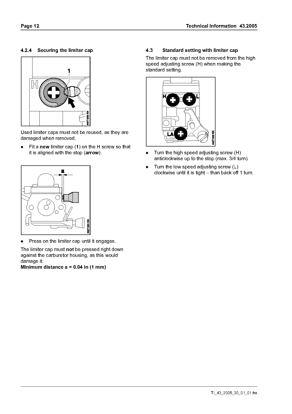
4.2.4   Securing the limiter cap                       4.3       Standard setting with limiter cap
                                                       The limiter cap must not be removed from the high
                                                       speed adjusting screw (H) when making the
                                                       standard setting.

Used limiter caps must not be reused, as they are
damaged when removed.
.   Fit a new limiter cap (1) on the H screw so that
    it is aligned with the stop (arrow).               .     Turn the high speed adjusting screw (H)
                                                             anticlockwise up to the stop (max. 3/4 turn).
                                                       .     Turn the low speed adjusting screw (L)
                                                             clockwise until it is tight – than back off 1 turn.

.   Press on the limiter cap until it engages.
The limiter cap must not be pressed right down
against the carburetor housing, as this would
damage it:
Minimum distance a = 0.04 in (1 mm)

                                                                                          TI_43_2005_30_01_01.fm
Page 13 of 14
Text of page 13 — search, copy, screen readers
Technical Information 43.2005                                                                      Page 13

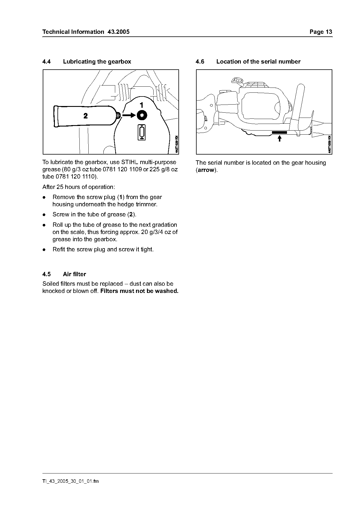
4.4       Lubricating the gearbox                         4.6    Location of the serial number

To lubricate the gearbox, use STIHL multi-purpose         The serial number is located on the gear housing
grease (80 g/3 oz tube 0781 120 1109 or 225 g/8 oz        (arrow).
tube 0781 120 1110).
After 25 hours of operation:
.     Remove the screw plug (1) from the gear
      housing underneath the hedge trimmer.
.     Screw in the tube of grease (2).
.     Roll up the tube of grease to the next gradation
      on the scale, thus forcing approx. 20 g/3/4 oz of
      grease into the gearbox.
.     Refit the screw plug and screw it tight.

4.5       Air filter
Soiled filters must be replaced – dust can also be
knocked or blown off. Filters must not be washed.

TI_43_2005_30_01_01.fm
Page 14 of 14
Text of page 14 — search, copy, screen readers
Page 14                                                                        Technical Information 43.2005

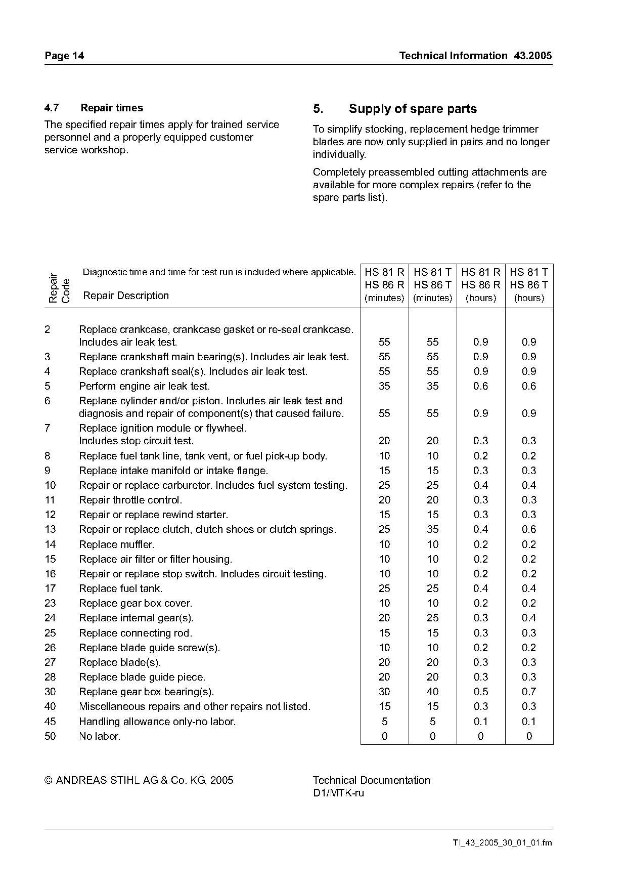
4.7      Repair times                                      5.     Supply of spare parts
The specified repair times apply for trained service       To simplify stocking, replacement hedge trimmer
personnel and a properly equipped customer                 blades are now only supplied in pairs and no longer
service workshop.                                          individually.
                                                           Completely preassembled cutting attachments are
                                                           available for more complex repairs (refer to the
                                                           spare parts list).

         Diagnostic time and time for test run is included where applicable. HS 81 R HS 81 T HS 81 R HS 81 T
Repair
Code

                                                                       HS 86 R HS 86 T HS 86 R HS 86 T
         Repair Description                                            (minutes) (minutes)     (hours)    (hours)

2        Replace crankcase, crankcase gasket or re-seal crankcase.
         Includes air leak test.                                         55         55           0.9        0.9
3        Replace crankshaft main bearing(s). Includes air leak test.     55         55           0.9        0.9
4        Replace crankshaft seal(s). Includes air leak test.             55         55           0.9        0.9
5        Perform engine air leak test.                                   35         35           0.6        0.6
6        Replace cylinder and/or piston. Includes air leak test and
         diagnosis and repair of component(s) that caused failure.        55        55           0.9        0.9
7        Replace ignition module or flywheel.
         Includes stop circuit test.                                     20         20           0.3        0.3
8        Replace fuel tank line, tank vent, or fuel pick-up body.        10         10           0.2        0.2
9        Replace intake manifold or intake flange.                       15         15           0.3        0.3
10       Repair or replace carburetor. Includes fuel system testing.     25         25           0.4        0.4
11       Repair throttle control.                                        20         20           0.3        0.3
12       Repair or replace rewind starter.                               15         15           0.3        0.3
13       Repair or replace clutch, clutch shoes or clutch springs.       25         35           0.4        0.6
14       Replace muffler.                                                10         10           0.2        0.2
15       Replace air filter or filter housing.                           10         10           0.2        0.2
16       Repair or replace stop switch. Includes circuit testing.        10         10           0.2        0.2
17       Replace fuel tank.                                              25         25           0.4        0.4
23       Replace gear box cover.                                         10         10           0.2        0.2
24       Replace internal gear(s).                                       20         25           0.3        0.4
25       Replace connecting rod.                                         15         15           0.3        0.3
26       Replace blade guide screw(s).                                   10         10           0.2        0.2
27       Replace blade(s).                                               20         20           0.3        0.3
28       Replace blade guide piece.                                      20         20           0.3        0.3
30       Replace gear box bearing(s).                                    30         40           0.5        0.7
40       Miscellaneous repairs and other repairs not listed.             15         15           0.3        0.3
45       Handling allowance only-no labor.                                5          5           0.1        0.1
50       No labor.                                                        0          0            0          0

© ANDREAS STIHL AG & Co. KG, 2005                          Technical Documentation
                                                           D1/MTK-ru

                                                                                             TI_43_2005_30_01_01.fm
Most of these PDFs embed fonts with a shifted character map, so the text above was recovered rather than copied — read it as a faithful but imperfect transcription, and treat the page image above each block as the authority where the two disagree — the figures exist only there, because they are vector drawings that text extraction cannot keep.