Technical Information · issue 47 of 2005
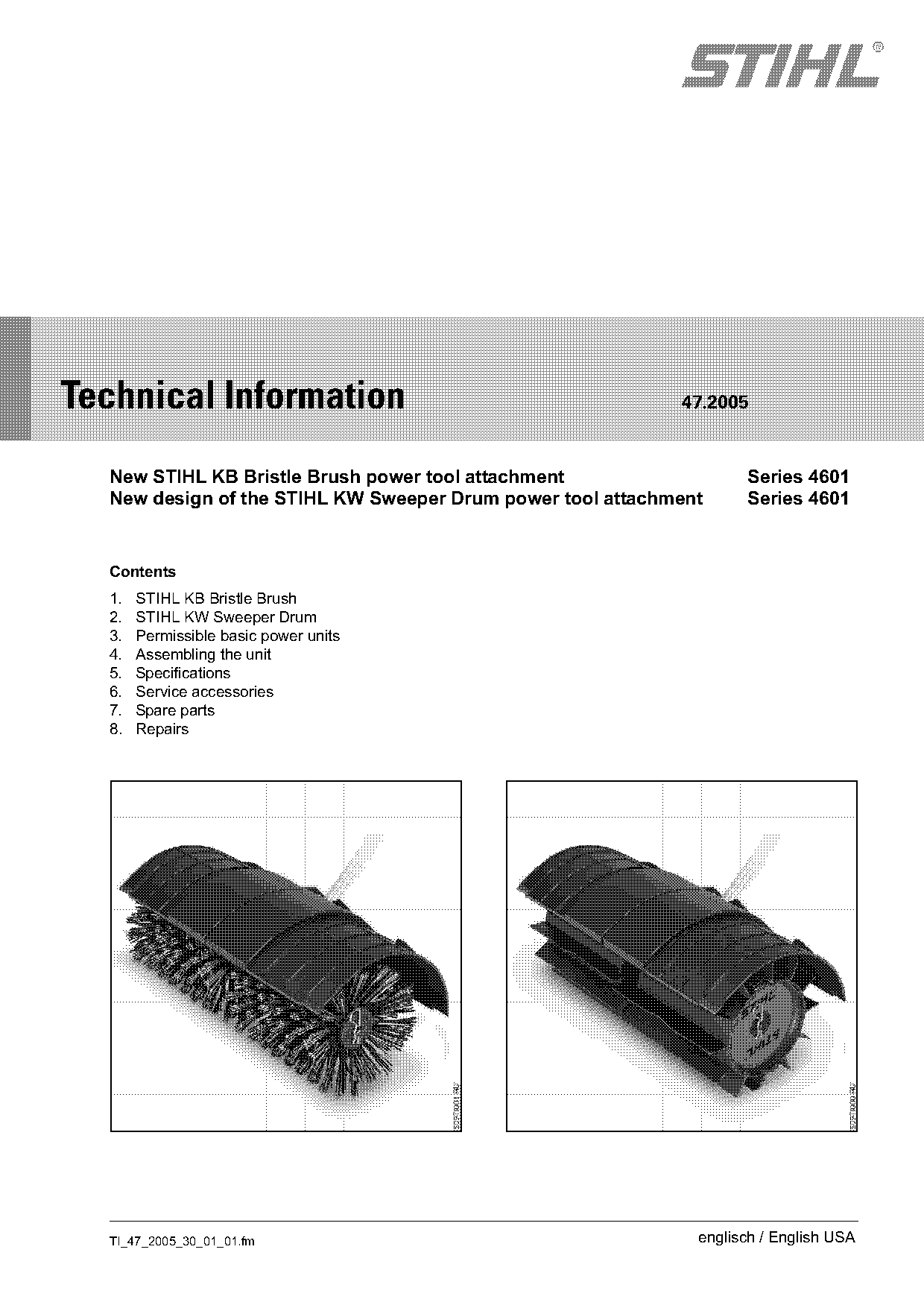
New STIHL KB Bristle Brush power tool attachment; New design of the STIHL KW Sweeper Drum power tool Attachment
IssueTI 47/2005
Full text
Page 1 of 6
Text of page 1 — search, copy, screen readers
STIH)

Technical Information                                       47.2005

  New STIHL KB Bristle Brush power tool attachment                  Series 4601
  New design of the STIHL KW Sweeper Drum power tool attachment     Series 4601

  Contents
  1.   STIHL KB Bristle Brush
  2.   STIHL KW Sweeper Drum
  3.   Permissible basic power units
  4.   Assembling the unit
  5.   Specifications
  6.   Service accessories
  7.   Spare parts
  8.   Repairs

  TI_47_2005_30_01_01.fm                                      englisch / English USA
Page 2 of 6
Text of page 2 — search, copy, screen readers
Page 2                                                                         Technical Information 47.2005

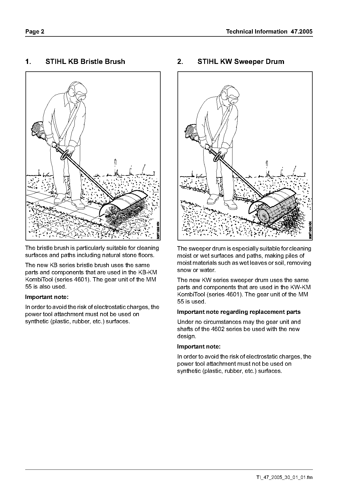
1.       STIHL KB Bristle Brush                            2.      STIHL KW Sweeper Drum

The bristle brush is particularly suitable for cleaning    The sweeper drum is especially suitable for cleaning
surfaces and paths including natural stone floors.         moist or wet surfaces and paths, making piles of
The new KB series bristle brush uses the same              moist materials such as wet leaves or soil, removing
parts and components that are used in the KB-KM            snow or water.
KombiTool (series 4601). The gear unit of the MM           The new KW series sweeper drum uses the same
55 is also used.                                           parts and components that are used in the KW-KM
Important note:                                            KombiTool (series 4601). The gear unit of the MM
                                                           55 is used.
In order to avoid the risk of electrostatic charges, the
power tool attachment must not be used on                  Important note regarding replacement parts
synthetic (plastic, rubber, etc.) surfaces.                Under no circumstances may the gear unit and
                                                           shafts of the 4602 series be used with the new
                                                           design.
                                                           Important note:
                                                           In order to avoid the risk of electrostatic charges, the
                                                           power tool attachment must not be used on
                                                           synthetic (plastic, rubber, etc.) surfaces.

                                                                                            TI_47_2005_30_01_01.fm
Page 3 of 6
Text of page 3 — search, copy, screen readers
Technical Information 47.2005                                                                             Page 3

3.       Permissible basic power units                   4.2       Mount the deflector

The STIHL KB and KW power tool attachments may
only be operated with the following basic power
units:
STIHL FC 83, STIHL FC 85, STIHL FC 110,
STIHL FH 75, STIHL FS 65-41), STIHL FS 831),
STIHL FS 851), STIHL FS 1101), STIHL HL 731),
STIHL HL 751), STIHL HL 1001) and STIHL KW 85
They must not be used in combination with other
basic power units.
1) They must not be mounted on units with bike
handles, nor on the following units: FS 85 X,
FS 100 RX, FS 110 X, HL 73 K, HL 73-0°,
HL 75 K, HL 75-0°, HL 100 K and HL 100-0°.

4.       Assembling the unit

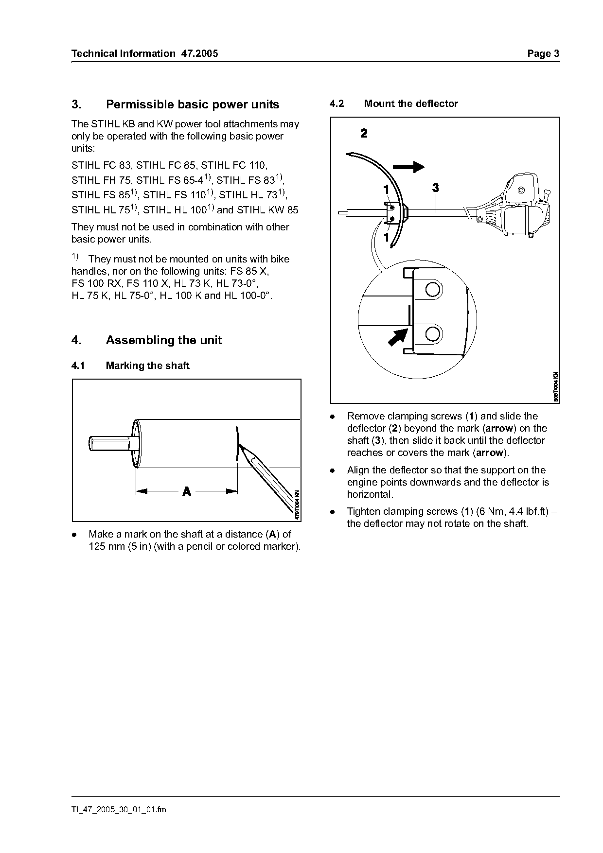
4.1      Marking the shaft

                                                         .     Remove clamping screws (1) and slide the
                                                               deflector (2) beyond the mark (arrow) on the
                                                               shaft (3), then slide it back until the deflector
                                                               reaches or covers the mark (arrow).
                                                         .     Align the deflector so that the support on the
                                                               engine points downwards and the deflector is
                                                               horizontal.
                                                         .     Tighten clamping screws (1) (6 Nm, 4.4 lbf.ft) –
                                                               the deflector may not rotate on the shaft.
.     Make a mark on the shaft at a distance (A) of
      125 mm (5 in) (with a pencil or colored marker).

TI_47_2005_30_01_01.fm
Page 4 of 6
Text of page 4 — search, copy, screen readers
Page 4                                                                            Technical Information 47.2005

4.3       Remove the sweeping tools                          4.4.1     Aligning the gearbox

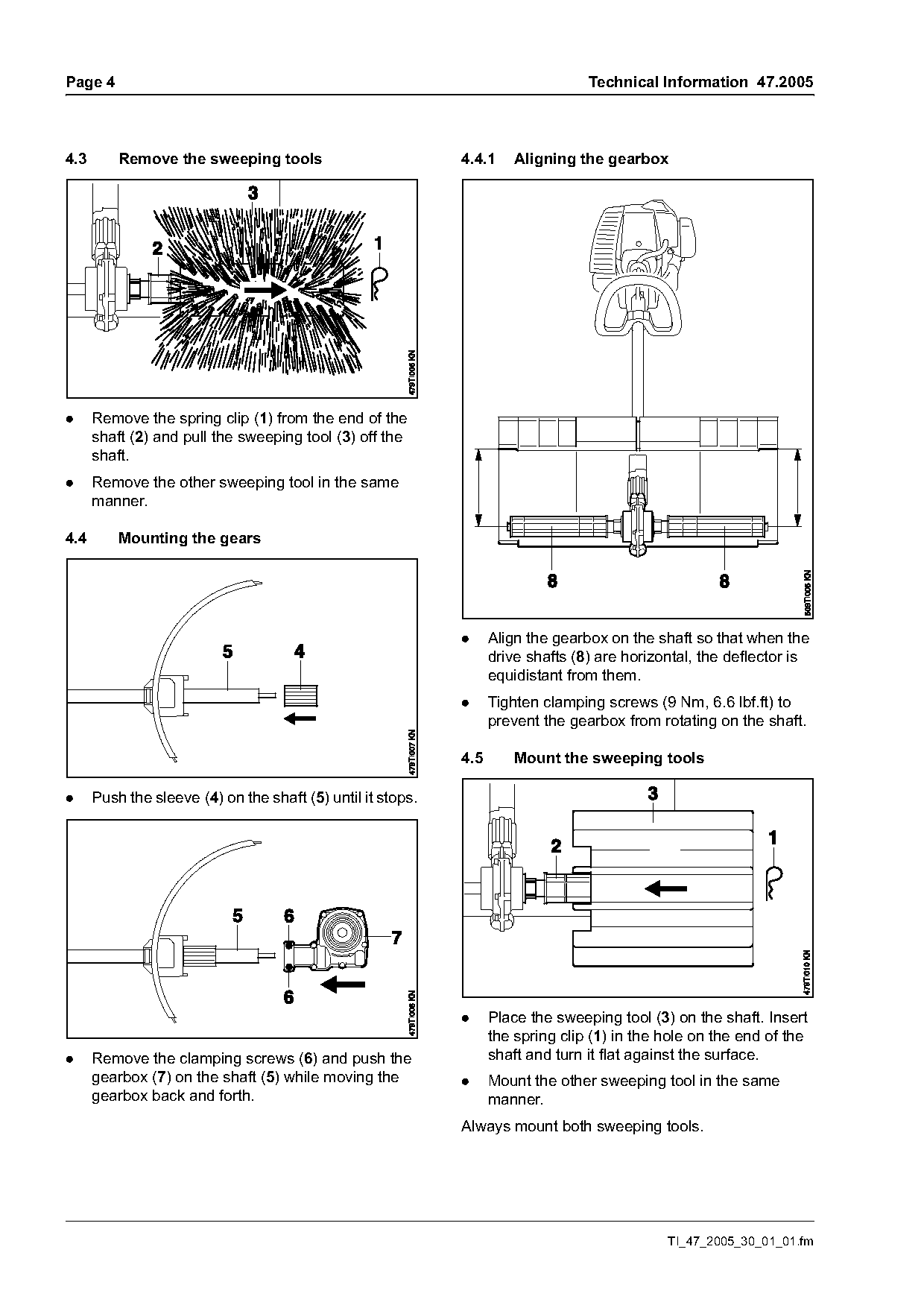
.     Remove the spring clip (1) from the end of the
      shaft (2) and pull the sweeping tool (3) off the
      shaft.
.     Remove the other sweeping tool in the same
      manner.

4.4       Mounting the gears

                                                             .     Align the gearbox on the shaft so that when the
                                                                   drive shafts (8) are horizontal, the deflector is
                                                                   equidistant from them.
                                                             .     Tighten clamping screws (9 Nm, 6.6 lbf.ft) to
                                                                   prevent the gearbox from rotating on the shaft.

                                                             4.5       Mount the sweeping tools

.     Push the sleeve (4) on the shaft (5) until it stops.

                                                             .     Place the sweeping tool (3) on the shaft. Insert
                                                                   the spring clip (1) in the hole on the end of the
.     Remove the clamping screws (6) and push the                  shaft and turn it flat against the surface.
      gearbox (7) on the shaft (5) while moving the          .     Mount the other sweeping tool in the same
      gearbox back and forth.                                      manner.
                                                             Always mount both sweeping tools.

                                                                                              TI_47_2005_30_01_01.fm
Page 5 of 6
Text of page 5 — search, copy, screen readers
Technical Information 47.2005                                                                            Page 5

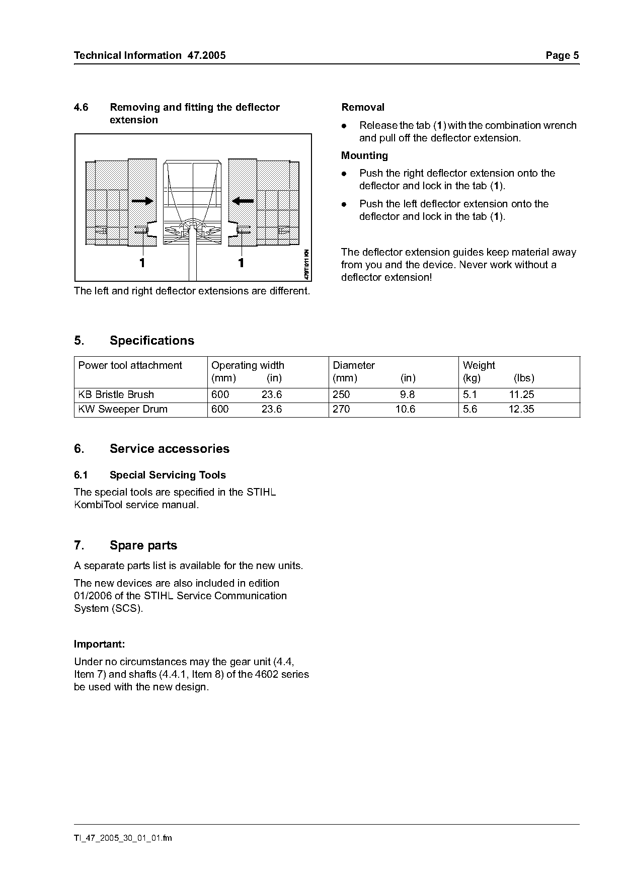
4.6     Removing and fitting the deflector                Removal
        extension
                                                          .    Release the tab (1) with the combination wrench
                                                               and pull off the deflector extension.
                                                          Mounting
                                                          .    Push the right deflector extension onto the
                                                               deflector and lock in the tab (1).
                                                          .    Push the left deflector extension onto the
                                                               deflector and lock in the tab (1).

                                                          The deflector extension guides keep material away
                                                          from you and the device. Never work without a
                                                          deflector extension!
The left and right deflector extensions are different.

5.      Specifications
Power tool attachment          Operating width           Diameter                    Weight
                               (mm)       (in)           (mm)           (in)         (kg)        (lbs)
KB Bristle Brush               600         23.6          250           9.8           5.1       11.25
KW Sweeper Drum                600         23.6          270          10.6           5.6       12.35

6.      Service accessories

6.1     Special Servicing Tools
The special tools are specified in the STIHL
KombiTool service manual.

7.      Spare parts
A separate parts list is available for the new units.
The new devices are also included in edition
01/2006 of the STIHL Service Communication
System (SCS).

Important:
Under no circumstances may the gear unit (4.4,
Item 7) and shafts (4.4.1, Item 8) of the 4602 series
be used with the new design.

TI_47_2005_30_01_01.fm
Page 6 of 6
Text of page 6 — search, copy, screen readers
Page 6                                                                  Technical Information 47.2005

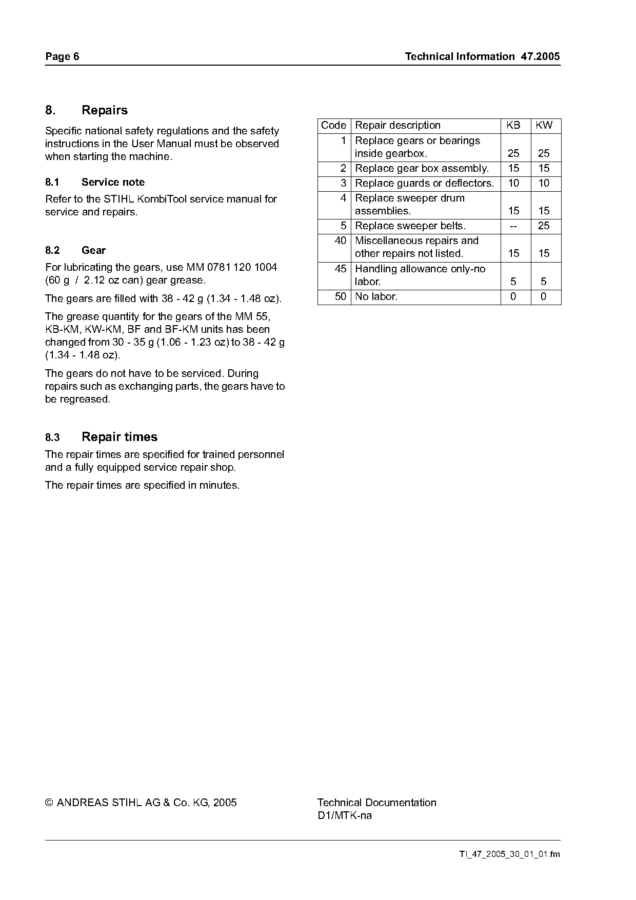
8.       Repairs
                                                        Code Repair description              KB    KW
Specific national safety regulations and the safety
instructions in the User Manual must be observed           1 Replace gears or bearings
when starting the machine.                                   inside gearbox.                 25     25
                                                           2 Replace gear box assembly.      15     15
8.1      Service note                                      3 Replace guards or deflectors.   10     10
Refer to the STIHL KombiTool service manual for            4 Replace sweeper drum
service and repairs.                                         assemblies.                     15     15
                                                           5 Replace sweeper belts.          --     25
                                                          40 Miscellaneous repairs and
8.2      Gear                                                other repairs not listed.       15     15
For lubricating the gears, use MM 0781 120 1004           45 Handling allowance only-no
(60 g / 2.12 oz can) gear grease.                            labor.                           5     5
The gears are filled with 38 - 42 g (1.34 - 1.48 oz).     50 No labor.                        0     0
The grease quantity for the gears of the MM 55,
KB-KM, KW-KM, BF and BF-KM units has been
changed from 30 - 35 g (1.06 - 1.23 oz) to 38 - 42 g
(1.34 - 1.48 oz).
The gears do not have to be serviced. During
repairs such as exchanging parts, the gears have to
be regreased.

8.3      Repair times
The repair times are specified for trained personnel
and a fully equipped service repair shop.
The repair times are specified in minutes.

© ANDREAS STIHL AG & Co. KG, 2005                       Technical Documentation
                                                        D1/MTK-na

                                                                                   TI_47_2005_30_01_01.fm
Most of these PDFs embed fonts with a shifted character map, so the text above was recovered rather than copied — read it as a faithful but imperfect transcription, and treat the page image above each block as the authority where the two disagree — the figures exist only there, because they are vector drawings that text extraction cannot keep.