Technical Information · issue 50 of 2005
New Model FC 95 Power Edger
IssueTI 50/2005
Full text
Page 1 of 7
Text of page 1 — search, copy, screen readers
STIH)

Technical Information                                                  50.2005

  New Model FC 95 Power Edger – Series 4180

  Contents
  1.   Technical Description
  2.   Specifications
  3.   Cutting Tools
  4.   Accessories
  5.   Service Accessories
  6.   Repairs
  7.   Spare Parts

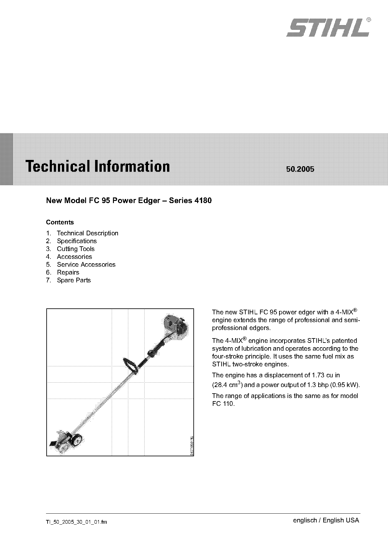
                                              The new STIHL FC 95 power edger with a 4-MIX®
                                              engine extends the range of professional and semi-
                                              professional edgers.
                                              The 4-MIX® engine incorporates STIHL’s patented
                                              system of lubrication and operates according to the
                                              four-stroke principle. It uses the same fuel mix as
                                              STIHL two-stroke engines.
                                              The engine has a displacement of 1.73 cu in
                                              (28.4 cm3) and a power output of 1.3 bhp (0.95 kW).
                                              The range of applications is the same as for model
                                              FC 110.

  TI_50_2005_30_01_01.fm                                                  englisch / English USA
Page 2 of 7
Text of page 2 — search, copy, screen readers
Page 2                                                                       Technical Information 50.2005

1.     Technical Description                            1.3       Gearbox and Deflector

1.1    STIHL 4-MIX® Engine                                               4
The 4-MIX® engine features gas-oil lubrication.
Compared to a conventional four-stroke engine, the
4-MIX® engine has no separate oil supply in the
crankcase. Engine lubrication is provided by the fuel
mixture of gasoline and 2-cycle engine oil.                                            4
The benefits of this new concept are:
.     Same familiar fuel mix as for STIHL two-stroke
      engines
                                                                             1
.     Favorable fuel consumption
.     Operates in all positions
.     Good acceleration
.     Compact construction – attractive design

                                                                                                               245TI001 KN
.     Favorable power-to-weight ratio                                              3             2   1
.     Simple maintenance – service-friendly
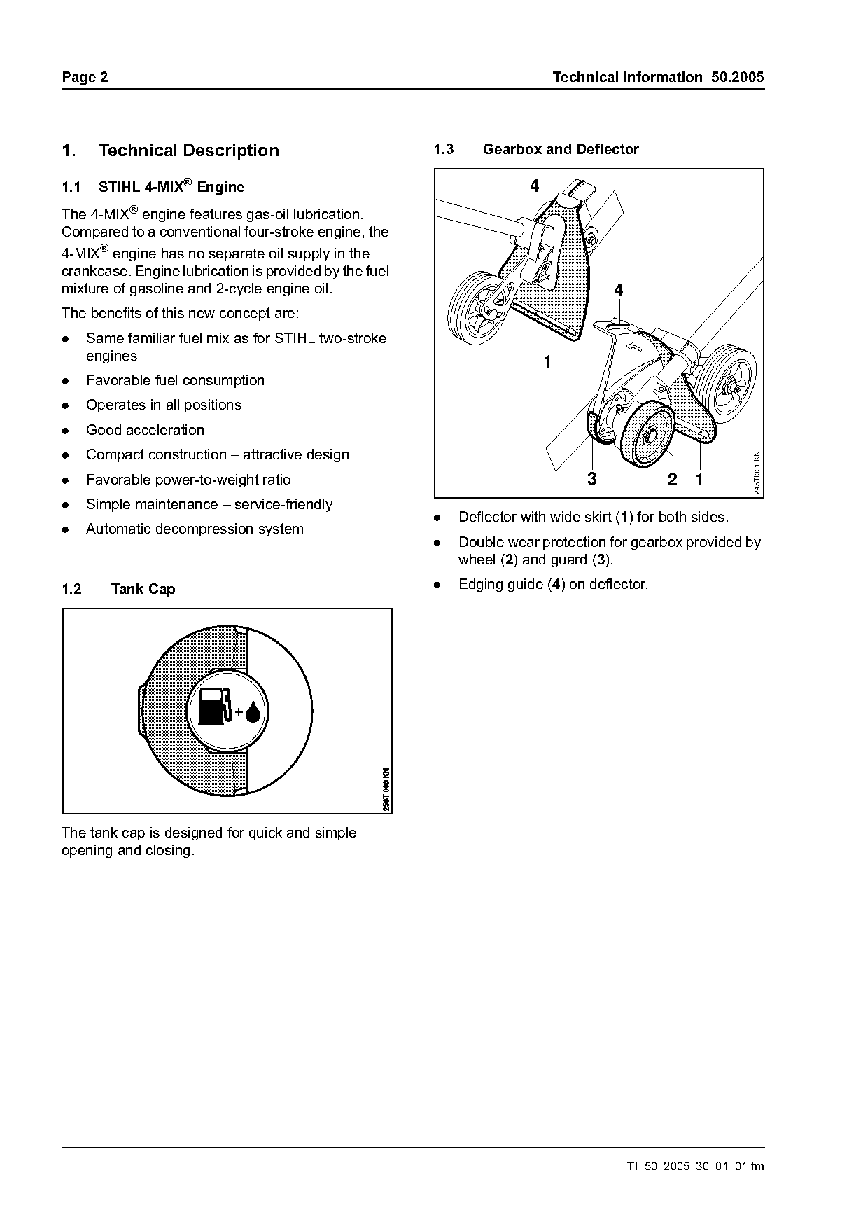
                                                        .     Deflector with wide skirt (1) for both sides.
.     Automatic decompression system
                                                        .     Double wear protection for gearbox provided by
                                                              wheel (2) and guard (3).

1.2      Tank Cap                                       .     Edging guide (4) on deflector.

The tank cap is designed for quick and simple
opening and closing.

                                                                                           TI_50_2005_30_01_01.fm
Page 3 of 7
Text of page 3 — search, copy, screen readers
Technical Information 50.2005                                                                       Page 3

2.      Specifications

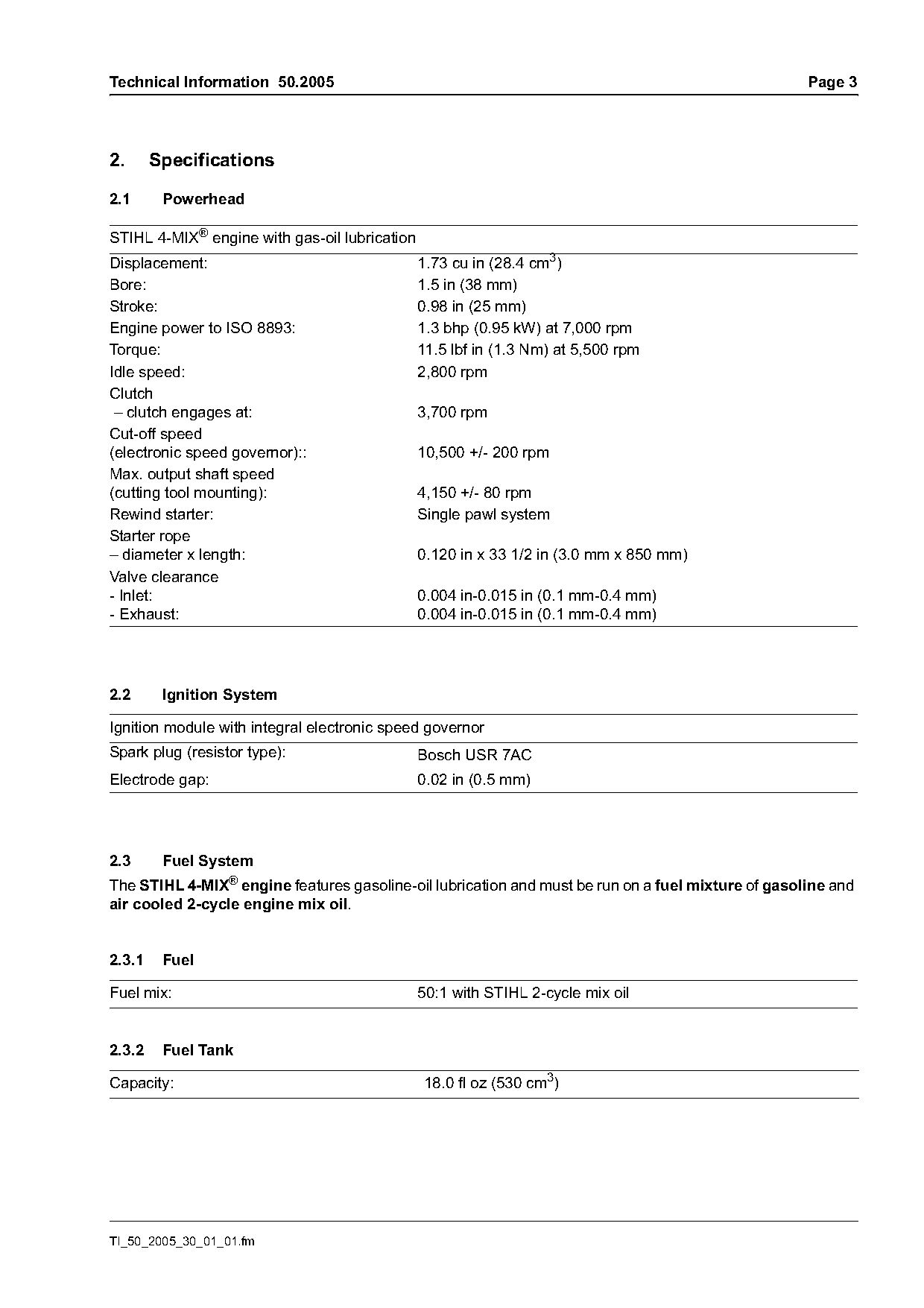
2.1      Powerhead

STIHL 4-MIX® engine with gas-oil lubrication
Displacement:                                  1.73 cu in (28.4 cm3)
Bore:                                          1.5 in (38 mm)
Stroke:                                        0.98 in (25 mm)
Engine power to ISO 8893:                      1.3 bhp (0.95 kW) at 7,000 rpm
Torque:                                        11.5 lbf in (1.3 Nm) at 5,500 rpm
Idle speed:                                    2,800 rpm
Clutch
 – clutch engages at:                          3,700 rpm
Cut-off speed
(electronic speed governor)::                  10,500 +/- 200 rpm
Max. output shaft speed
(cutting tool mounting):                       4,150 +/- 80 rpm
Rewind starter:                                Single pawl system
Starter rope
– diameter x length:                           0.120 in x 33 1/2 in (3.0 mm x 850 mm)
Valve clearance
- Inlet:                                       0.004 in-0.015 in (0.1 mm-0.4 mm)
- Exhaust:                                     0.004 in-0.015 in (0.1 mm-0.4 mm)

2.2      Ignition System

Ignition module with integral electronic speed governor
Spark plug (resistor type):                    Bosch USR 7AC
Electrode gap:                                 0.02 in (0.5 mm)

2.3      Fuel System
The STIHL 4-MIX® engine features gasoline-oil lubrication and must be run on a fuel mixture of gasoline and
air cooled 2-cycle engine mix oil.

2.3.1    Fuel

Fuel mix:                                      50:1 with STIHL 2-cycle mix oil

2.3.2    Fuel Tank

Capacity:                                      18.0 fl oz (530 cm3)

TI_50_2005_30_01_01.fm
Page 4 of 7
Text of page 4 — search, copy, screen readers
Page 4                                                                      Technical Information 50.2005

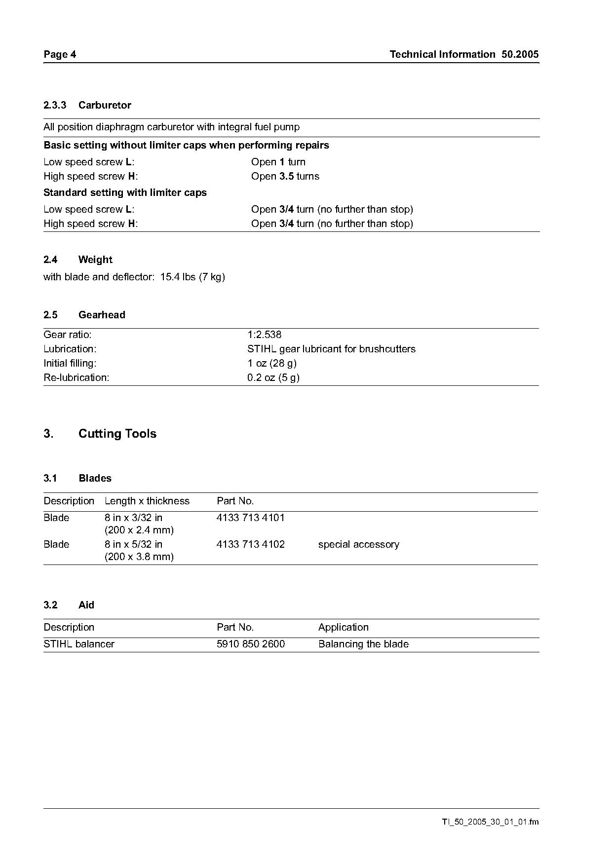
2.3.3    Carburetor

All position diaphragm carburetor with integral fuel pump
Basic setting without limiter caps when performing repairs
Low speed screw L:                            Open 1 turn
High speed screw H:                           Open 3.5 turns
Standard setting with limiter caps
Low speed screw L:                            Open 3/4 turn (no further than stop)
High speed screw H:                           Open 3/4 turn (no further than stop)

2.4      Weight
with blade and deflector: 15.4 lbs (7 kg)

2.5      Gearhead
Gear ratio:                                  1:2.538
Lubrication:                                 STIHL gear lubricant for brushcutters
Initial filling:                             1 oz (28 g)
Re-lubrication:                              0.2 oz (5 g)

3.       Cutting Tools

3.1      Blades

Description Length x thickness         Part No.
Blade          8 in x 3/32 in          4133 713 4101
               (200 x 2.4 mm)
Blade          8 in x 5/32 in          4133 713 4102        special accessory
               (200 x 3.8 mm)

3.2      Aid

Description                            Part No.             Application
STIHL balancer                         5910 850 2600        Balancing the blade

                                                                                      TI_50_2005_30_01_01.fm
Page 5 of 7
Text of page 5 — search, copy, screen readers
Technical Information 50.2005                                                                            Page 5

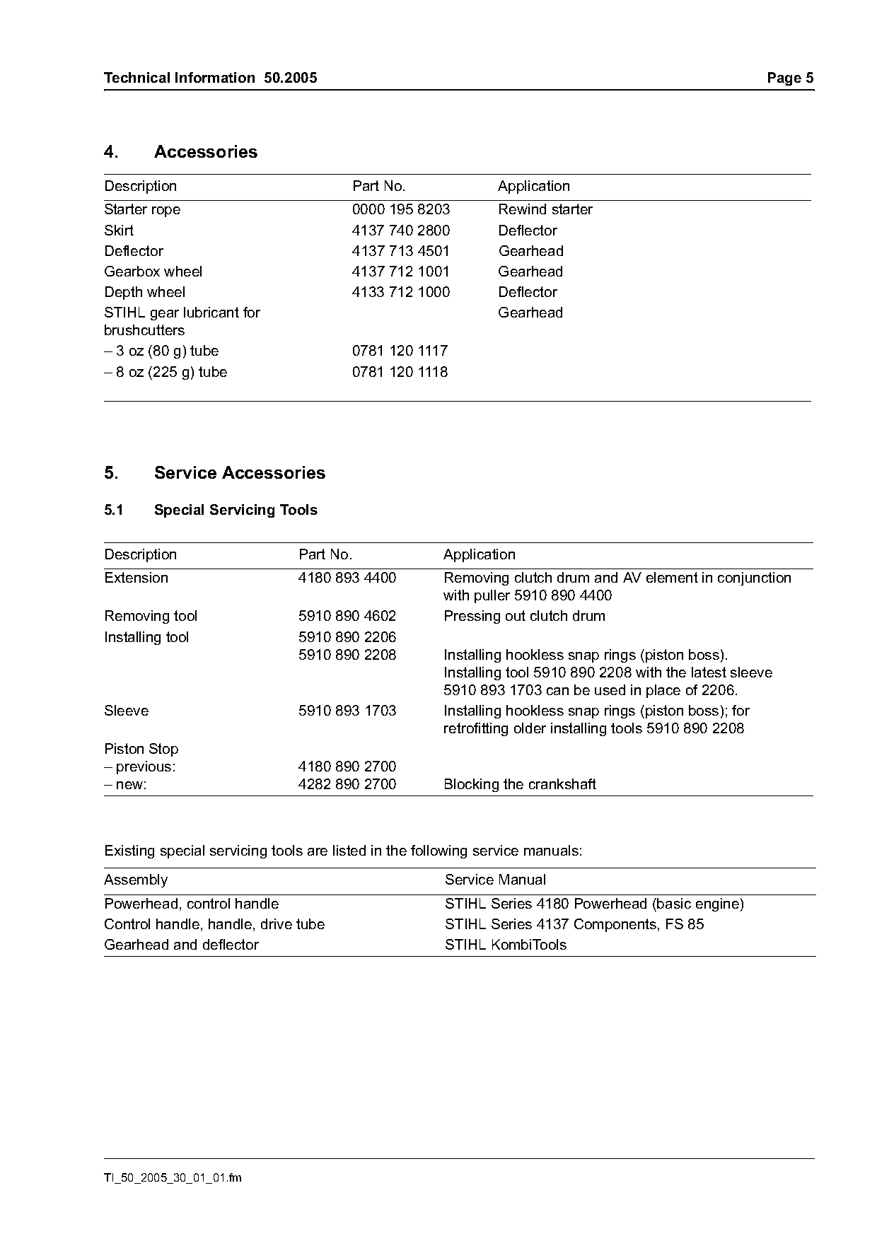
4.       Accessories
Description                            Part No.                Application
Starter rope                           0000 195 8203           Rewind starter
Skirt                                  4137 740 2800           Deflector
Deflector                              4137 713 4501           Gearhead
Gearbox wheel                          4137 712 1001           Gearhead
Depth wheel                            4133 712 1000           Deflector
STIHL gear lubricant for                                       Gearhead
brushcutters
– 3 oz (80 g) tube                     0781 120 1117
– 8 oz (225 g) tube                    0781 120 1118

5.       Service Accessories

5.1      Special Servicing Tools

Description                    Part No.               Application
Extension                      4180 893 4400          Removing clutch drum and AV element in conjunction
                                                      with puller 5910 890 4400
Removing tool                  5910 890 4602          Pressing out clutch drum
Installing tool                5910 890 2206
                               5910 890 2208          Installing hookless snap rings (piston boss).
                                                      Installing tool 5910 890 2208 with the latest sleeve
                                                      5910 893 1703 can be used in place of 2206.
Sleeve                         5910 893 1703          Installing hookless snap rings (piston boss); for
                                                      retrofitting older installing tools 5910 890 2208
Piston Stop
– previous:                    4180 890 2700
– new:                         4282 890 2700          Blocking the crankshaft

Existing special servicing tools are listed in the following service manuals:

Assembly                                              Service Manual
Powerhead, control handle                             STIHL Series 4180 Powerhead (basic engine)
Control handle, handle, drive tube                    STIHL Series 4137 Components, FS 85
Gearhead and deflector                                STIHL KombiTools

TI_50_2005_30_01_01.fm
Page 6 of 7
Text of page 6 — search, copy, screen readers
Page 6                                                                          Technical Information 50.2005

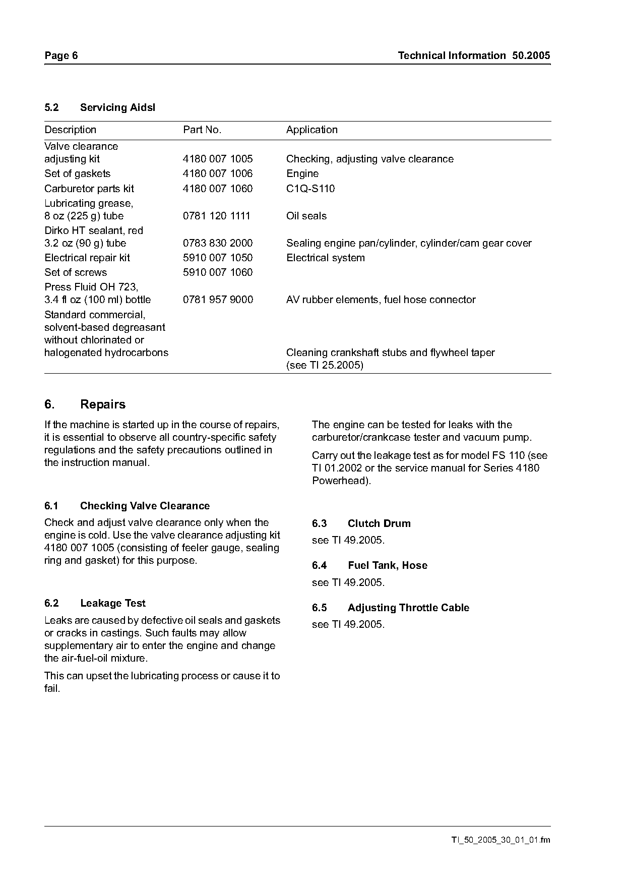
5.2      Servicing Aidsl

Description                    Part No.                  Application
Valve clearance
adjusting kit                  4180 007 1005             Checking, adjusting valve clearance
Set of gaskets                 4180 007 1006             Engine
Carburetor parts kit           4180 007 1060             C1Q-S110
Lubricating grease,
8 oz (225 g) tube              0781 120 1111             Oil seals
Dirko HT sealant, red
3.2 oz (90 g) tube             0783 830 2000             Sealing engine pan/cylinder, cylinder/cam gear cover
Electrical repair kit          5910 007 1050             Electrical system
Set of screws                  5910 007 1060
Press Fluid OH 723,
3.4 fl oz (100 ml) bottle      0781 957 9000             AV rubber elements, fuel hose connector
Standard commercial,
solvent-based degreasant
without chlorinated or
halogenated hydrocarbons                                 Cleaning crankshaft stubs and flywheel taper
                                                         (see TI 25.2005)

6.       Repairs
If the machine is started up in the course of repairs,        The engine can be tested for leaks with the
it is essential to observe all country-specific safety        carburetor/crankcase tester and vacuum pump.
regulations and the safety precautions outlined in            Carry out the leakage test as for model FS 110 (see
the instruction manual.                                       TI 01.2002 or the service manual for Series 4180
                                                              Powerhead).

6.1      Checking Valve Clearance
Check and adjust valve clearance only when the                6.3      Clutch Drum
engine is cold. Use the valve clearance adjusting kit         see TI 49.2005.
4180 007 1005 (consisting of feeler gauge, sealing
ring and gasket) for this purpose.                            6.4      Fuel Tank, Hose
                                                              see TI 49.2005.

6.2      Leakage Test                                         6.5      Adjusting Throttle Cable
Leaks are caused by defective oil seals and gaskets           see TI 49.2005.
or cracks in castings. Such faults may allow
supplementary air to enter the engine and change
the air-fuel-oil mixture.
This can upset the lubricating process or cause it to
fail.

                                                                                            TI_50_2005_30_01_01.fm
Page 7 of 7
Text of page 7 — search, copy, screen readers
Technical Information 50.2005                                                                          Page 7

6.6    Tightening Torques
The tightening torques are listed in the following service manuals:

Assembly                                             Service Manual
Powerhead, control handle                            STIHL Series 4180 Powerhead (basic engine)
Control handle, handle, drive tube                   STIHL Series 4137 Components, FS 85
Gearhead and deflector                               STIHL KombiTools

6.7    Service Note
The following service manuals are available for servicing and repairing:

Assembly                                             Service Manual
Powerhead                                            STIHL Service Training System “Diagnosis”
Powerhead, control handle                            STIHL Series 4180 Powerhead (basic engine)
Control handle, handle, drive tube                   STIHL Series 4137 Components, FS 85
Gearhead and deflector                               STIHL KombiTools

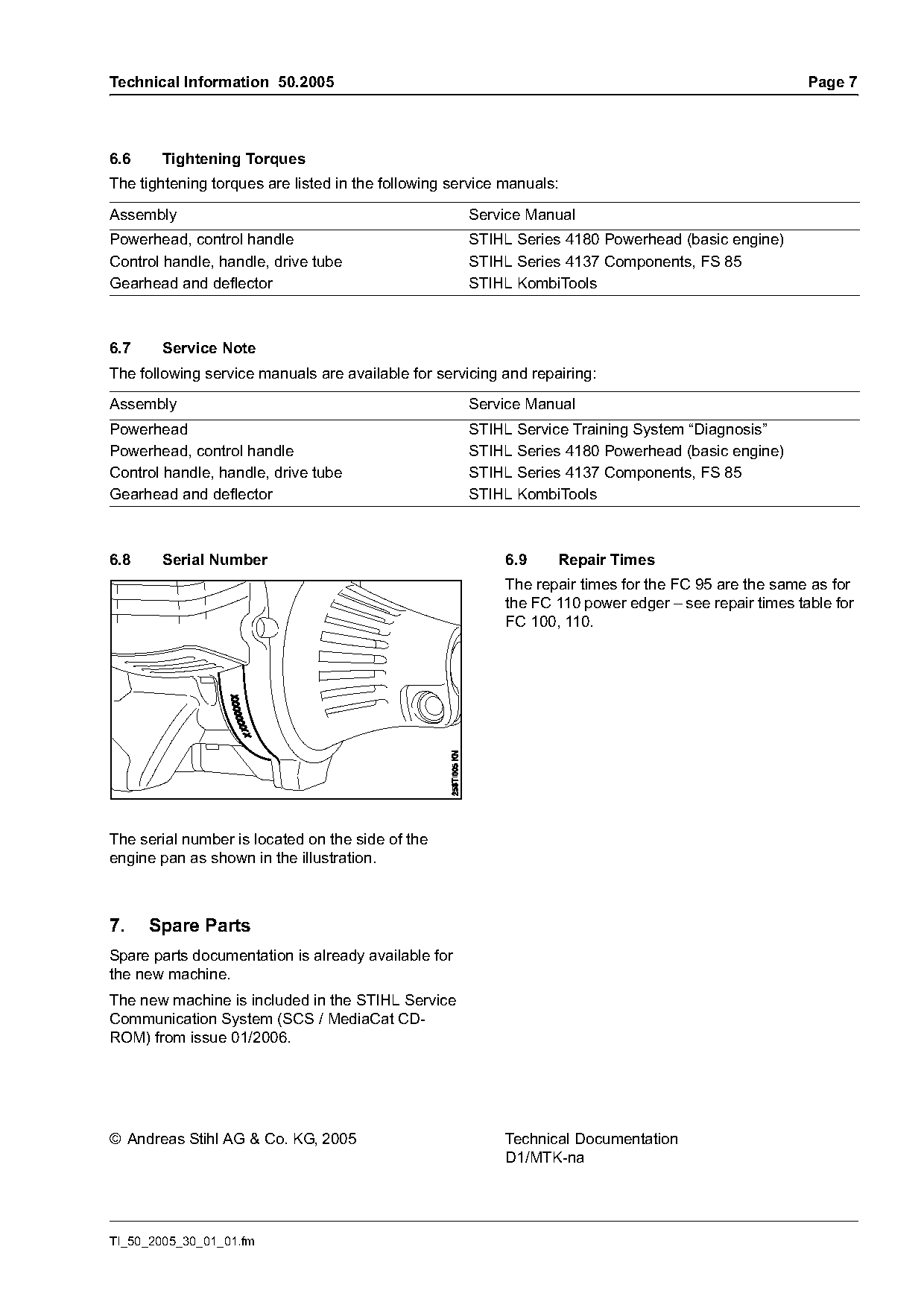
6.8    Serial Number                                       6.9    Repair Times
                                                           The repair times for the FC 95 are the same as for
                                                           the FC 110 power edger – see repair times table for
                                                           FC 100, 110.

The serial number is located on the side of the
engine pan as shown in the illustration.

7.    Spare Parts
Spare parts documentation is already available for
the new machine.
The new machine is included in the STIHL Service
Communication System (SCS /                 ) from issue 01/2006.

© Andreas Stihl AG & Co. KG, 2005                          Technical Documentation
                                                           D1/MTK-na

TI_50_2005_30_01_01.fm
Most of these PDFs embed fonts with a shifted character map, so the text above was recovered rather than copied — read it as a faithful but imperfect transcription, and treat the page image above each block as the authority where the two disagree — the figures exist only there, because they are vector drawings that text extraction cannot keep.