Technical Information · issue 54 of 2005
Power unit: valve; Throttle cable; Summary
IssueTI 54/2005
Part changes (2)
| Was | Becomes | What the bulletin says |
|---|---|---|
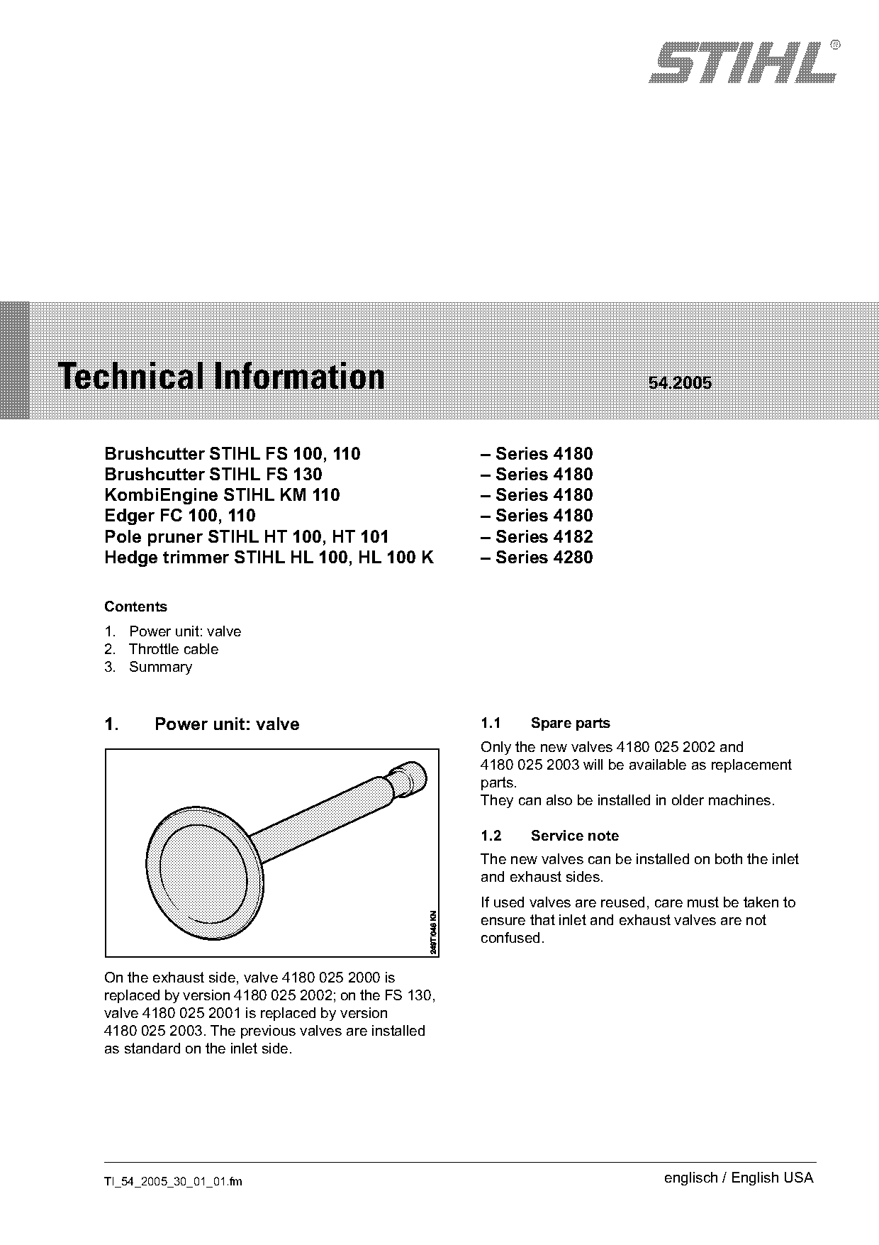
| 4180 025 2000 | 4180 025 2002 | On the exhaust side, valve 4180 025 2000 is replaced by version 4180 025 2002; on the FS 130, valve 4180 025 2001 is replaced by version 4180 025 2003. |
| 4180 025 2001 | 4180 025 2003 | On the exhaust side, valve 4180 025 2000 is replaced by version 4180 025 2002; on the FS 130, valve 4180 025 2001 is replaced by version 4180 025 2003. |
Full text
Page 1 of 4
Text of page 1 — search, copy, screen readers
STIH)

Technical Information                                                          54.2005

  Brushcutter STIHL FS 100, 110                       – Series 4180
  Brushcutter STIHL FS 130                            – Series 4180
  KombiEngine STIHL KM 110                            – Series 4180
  Edger FC 100, 110                                   – Series 4180
  Pole pruner STIHL HT 100, HT 101                    – Series 4182
  Hedge trimmer STIHL HL 100, HL 100 K                – Series 4280

  Contents
  1. Power unit: valve
  2. Throttle cable
  3. Summary

  1.     Power unit: valve                            1.1    Spare parts
                                                      Only the new valves 4180 025 2002 and
                                                      4180 025 2003 will be available as replacement
                                                      parts.
                                                      They can also be installed in older machines.

                                                      1.2    Service note
                                                      The new valves can be installed on both the inlet
                                                      and exhaust sides.
                                                      If used valves are reused, care must be taken to
                                                      ensure that inlet and exhaust valves are not
                                                      confused.

  On the exhaust side, valve 4180 025 2000 is
  replaced by version 4180 025 2002; on the FS 130,
  valve 4180 025 2001 is replaced by version
  4180 025 2003. The previous valves are installed
  as standard on the inlet side.

  TI_54_2005_30_01_01.fm                                                          englisch / English USA
Page 2 of 4
Text of page 2 — search, copy, screen readers
Page 2                                                                   Technical Information 54.2005

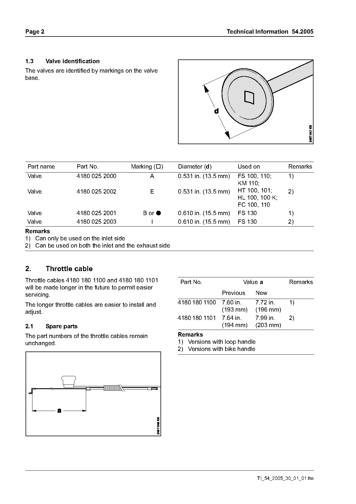
1.3      Valve identification
The valves are identified by markings on the valve
base.

Part name           Part No.             Marking ())    Diameter (d)          Used on              Remarks
Valve               4180 025 2000                A      0.531 in. (13.5 mm)   FS 100, 110;         1)
                                                                              KM 110;
Valve               4180 025 2002                E      0.531 in. (13.5 mm)   HT 100, 101;         2)
                                                                              HL 100, 100 K;
                                                                              FC 100, 110
Valve               4180 025 2001             B or :    0.610 in. (15.5 mm)   FS 130               1)
Valve               4180 025 2003                I      0.610 in. (15.5 mm)   FS 130               2)
Remarks
1) Can only be used on the inlet side
2) Can be used on both the inlet and the exhaust side

2.       Throttle cable
Throttle cables 4180 180 1100 and 4180 180 1101         Part No.               Value a             Remarks
will be made longer in the future to permit easier
servicing.                                                              Previous    New

The longer throttle cables are easier to install and    4180 180 1100 7.60 in.      7.72 in.       1)
adjust.                                                               (193 mm)      (196 mm)
                                                        4180 180 1101 7.64 in.      7.99 in.       2)
2.1      Spare parts                                                  (194 mm)      (203 mm)
The part numbers of the throttle cables remain          Remarks
unchanged.                                              1) Versions with loop handle
                                                        2) Versions with bike handle

                                                                                       TI_54_2005_30_01_01.fm
Page 3 of 4
Text of page 3 — search, copy, screen readers
Technical Information 54.2005                                                                                          Page 3

2.2       Service note

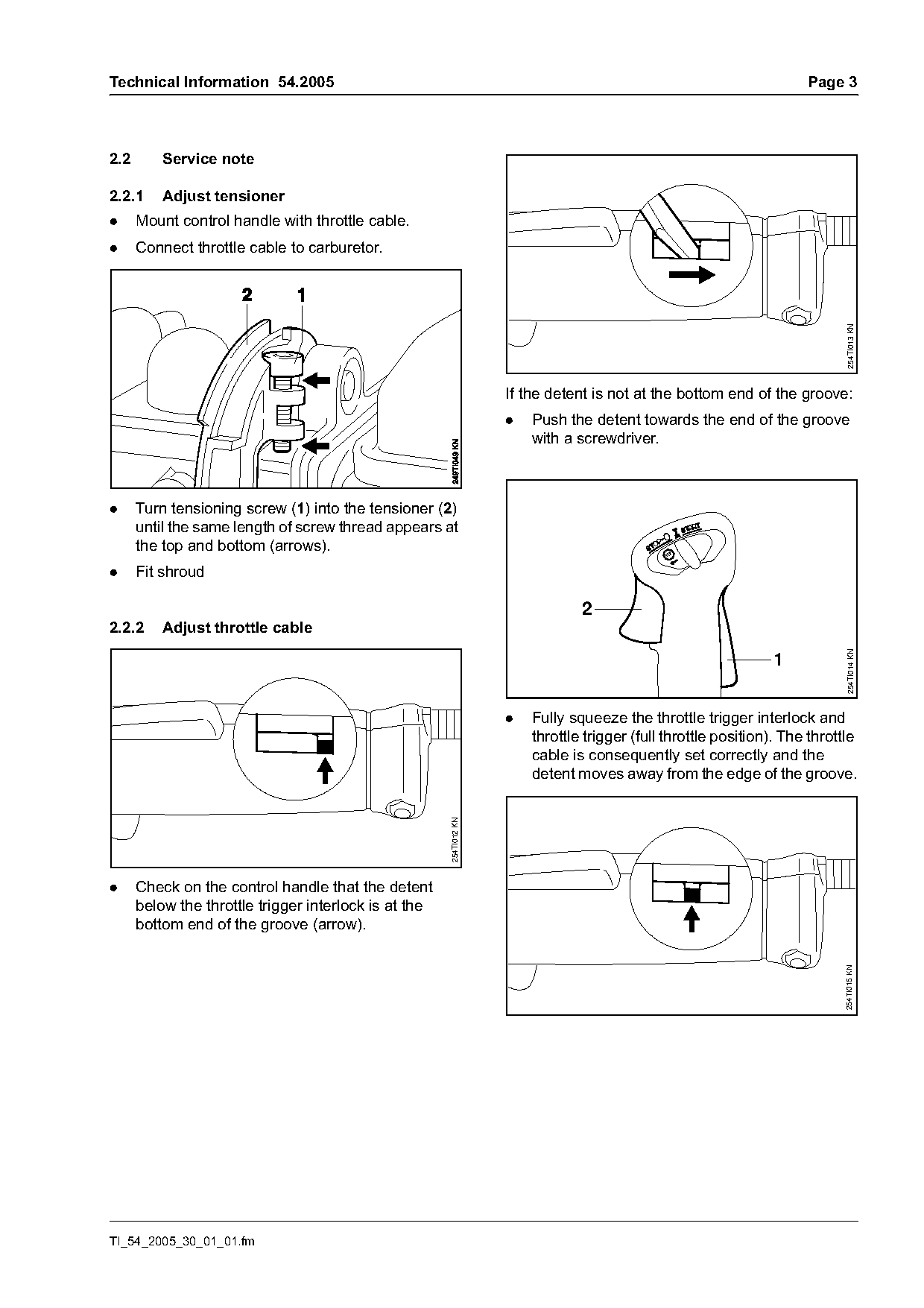
2.2.1     Adjust tensioner
.     Mount control handle with throttle cable.
.     Connect throttle cable to carburetor.

                                                                                                                                254TI013 KN
                                                                     If the detent is not at the bottom end of the groove:
                                                                     .   Push the detent towards the end of the groove
                                                                         with a screwdriver.

.     Turn tensioning screw (1) into the tensioner (2)
      until the same length of screw thread appears at
      the top and bottom (arrows).                                                             STO

.     Fit shroud

                                                                                 2
2.2.2     Adjust throttle cable

                                                                                                                                254TI014 KN
                                                                                                                 1

                                                                     .   Fully squeeze the throttle trigger interlock and
                                                                         throttle trigger (full throttle position). The throttle
                                                                         cable is consequently set correctly and the
                                                                         detent moves away from the edge of the groove.
                                                       254TI012 KN

.     Check on the control handle that the detent
      below the throttle trigger interlock is at the
      bottom end of the groove (arrow).
                                                                                                                              254TI015 KN

TI_54_2005_30_01_01.fm
Page 4 of 4
Text of page 4 — search, copy, screen readers
Page 4                                                                               Technical Information 54.2005

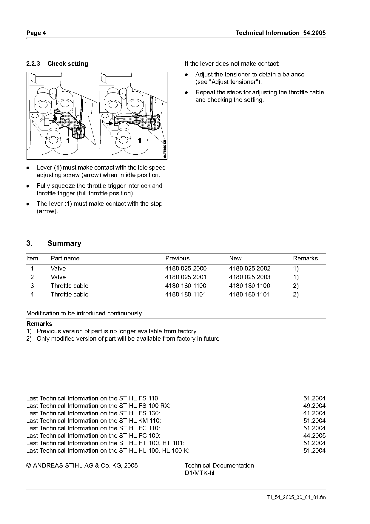
2.2.3       Check setting                                        If the lever does not make contact:
                                                                 .    Adjust the tensioner to obtain a balance
                                                                      (see "Adjust tensioner").
                                                                 .    Repeat the steps for adjusting the throttle cable
                                                                      and checking the setting.

.       Lever (1) must make contact with the idle speed
        adjusting screw (arrow) when in idle position.
.       Fully squeeze the throttle trigger interlock and
        throttle trigger (full throttle position).
.       The lever (1) must make contact with the stop
        (arrow).

3.          Summary
Item         Part name                                     Previous               New                      Remarks
    1        Valve                                         4180 025 2000          4180 025 2002            1)
    2        Valve                                         4180 025 2001          4180 025 2003            1)
    3        Throttle cable                                4180 180 1100          4180 180 1100            2)
    4        Throttle cable                                4180 180 1101          4180 180 1101            2)

Modification to be introduced continuously
Remarks
1) Previous version of part is no longer available from factory
2) Only modified version of part will be available from factory in future

Last Technical Information on the STIHL FS 110:                                                                 51.2004
Last Technical Information on the STIHL FS 100 RX:                                                              49.2004
Last Technical Information on the STIHL FS 130:                                                                 41.2004
Last Technical Information on the STIHL KM 110:                                                                 51.2004
Last Technical Information on the STIHL FC 110:                                                                 51.2004
Last Technical Information on the STIHL FC 100:                                                                 44.2005
Last Technical Information on the STIHL HT 100, HT 101:                                                         51.2004
Last Technical Information on the STIHL HL 100, HL 100 K:                                                       51.2004

© ANDREAS STIHL AG & Co. KG, 2005                                Technical Documentation
                                                                 D1/MTK-bl

                                                                                                 TI_54_2005_30_01_01.fm
Most of these PDFs embed fonts with a shifted character map, so the text above was recovered rather than copied — read it as a faithful but imperfect transcription, and treat the page image above each block as the authority where the two disagree — the figures exist only there, because they are vector drawings that text extraction cannot keep.