Technical Information · issue 2 of 2006
New STIHL KombiEngine KM 130 R
IssueTI 2/2006
Full text
Page 1 of 8
Text of page 1 — search, copy, screen readers
STIH)

Technical Information                                02.2006

  New STIHL KombiEngine KM 130 R – Series 4180

  Contents
  1.   STIHL KombiEngine KM 130 R
  2.   Technical description
  3.   Specifications
  4.   KombiTools
  5.   Servicing accessories
  6.   Repairs

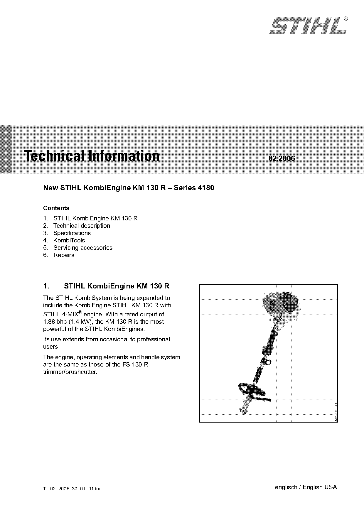
  1.      STIHL KombiEngine KM 130 R
  The STIHL KombiSystem is being expanded to
  include the KombiEngine STIHL KM 130 R with
  STIHL 4-MIX® engine. With a rated output of
  1.88 bhp (1.4 kW), the KM 130 R is the most
  powerful of the STIHL KombiEngines.
  Its use extends from occasional to professional
  users.
  The engine, operating elements and handle system
  are the same as those of the FS 130 R
  trimmer/brushcutter.

  TI_02_2006_30_01_01.fm                              englisch / English USA
Page 2 of 8
Text of page 2 — search, copy, screen readers
Page 2                                                                        Technical Information 02.2006

2.        Technical description                        2.2       Drive tube / shafts / coupling system

2.1       STIHL 4-MIX® engine
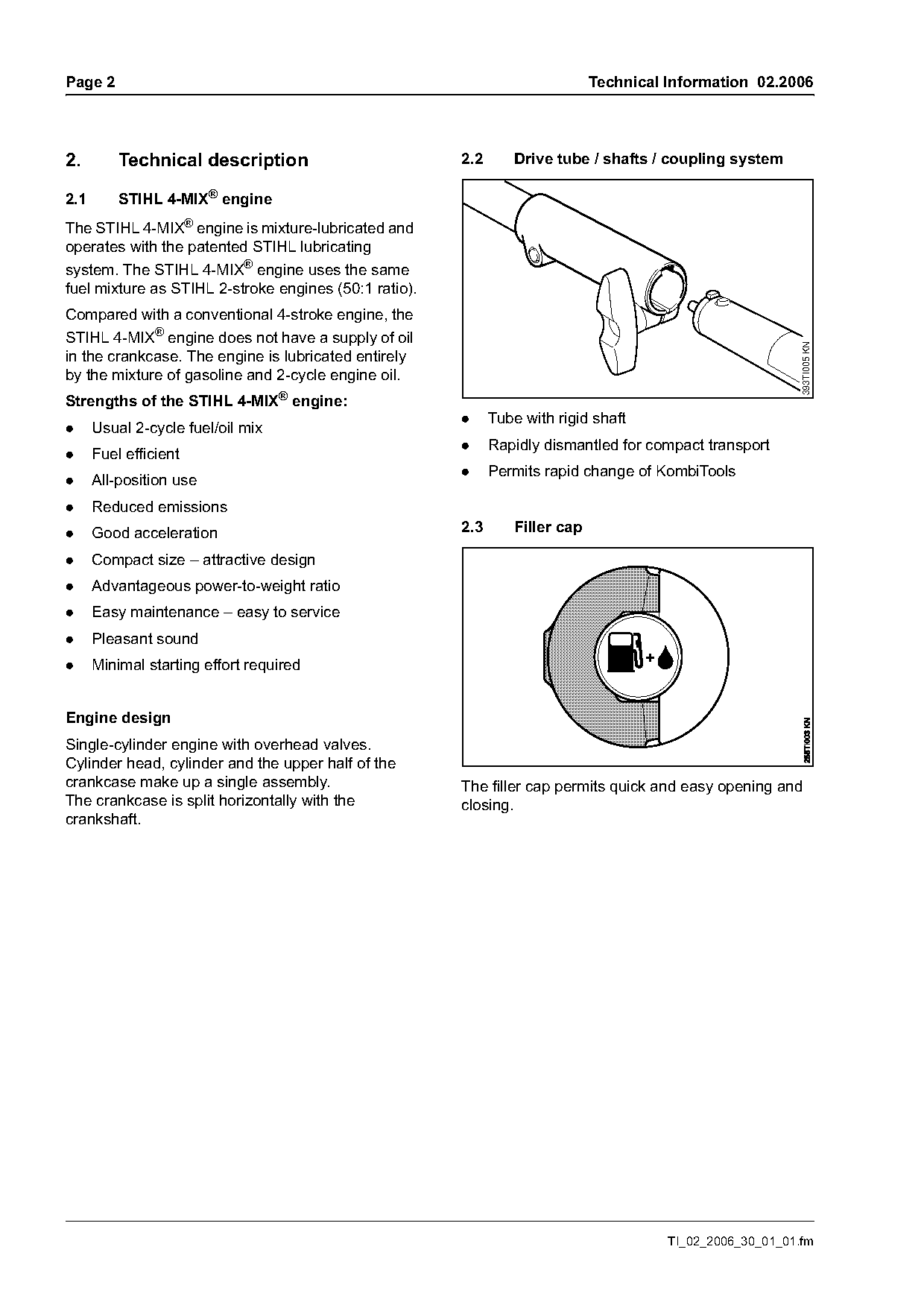
The STIHL 4-MIX® engine is mixture-lubricated and
operates with the patented STIHL lubricating
system. The STIHL 4-MIX® engine uses the same
fuel mixture as STIHL 2-stroke engines (50:1 ratio).
Compared with a conventional 4-stroke engine, the
STIHL 4-MIX® engine does not have a supply of oil

                                                                                                            393TI005 KN
in the crankcase. The engine is lubricated entirely
by the mixture of gasoline and 2-cycle engine oil.
Strengths of the STIHL 4-MIX® engine:
                                                       .     Tube with rigid shaft
.     Usual 2-cycle fuel/oil mix
                                                       .     Rapidly dismantled for compact transport
.     Fuel efficient
                                                       .     Permits rapid change of KombiTools
.     All-position use
.     Reduced emissions
.     Good acceleration                                2.3       Filler cap

.     Compact size – attractive design
.     Advantageous power-to-weight ratio
.     Easy maintenance – easy to service
.     Pleasant sound
.     Minimal starting effort required

Engine design
Single-cylinder engine with overhead valves.
Cylinder head, cylinder and the upper half of the
crankcase make up a single assembly.                   The filler cap permits quick and easy opening and
The crankcase is split horizontally with the           closing.
crankshaft.

                                                                                        TI_02_2006_30_01_01.fm
Page 3 of 8
Text of page 3 — search, copy, screen readers
Technical Information 02.2006                                                                     Page 3

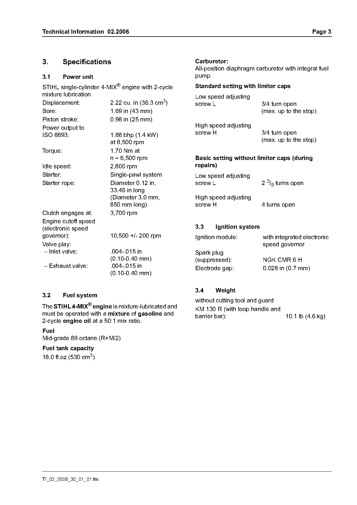
3.     Specifications                               Carburetor:
                                                    All-position diaphragm carburetor with integral fuel
3.1    Power unit                                   pump
STIHL single-cylinder 4-MIX® engine with 2-cycle    Standard setting with limiter caps
mixture lubrication                                 Low speed adjusting
Displacement:            2.22 cu. in (36.3 cm3)     screw L                  3/4 turn open
Bore:                    1.69 in (43 mm)                                     (max. up to the stop)
Piston stroke:           0.98 in (25 mm)
Power output to                                     High speed adjusting
ISO 8893:                1.88 bhp (1.4 kW)          screw H                  3/4 turn open
                         at 8,500 rpm                                        (max. up to the stop)
Torque:                  1.70 Nm at
                         n = 6,500 rpm              Basic setting without limiter caps (during
Idle speed:              2,800 rpm                  repairs)
Starter:                 Single-pawl system         Low speed adjusting
Starter rope:            Diameter 0.12 in,          screw L                  2 3/8 turns open
                         33.46 in long
                         (Diameter 3.0 mm,          High speed adjusting
                         850 mm long)               screw H                  4 turns open
Clutch engages at:       3,700 rpm
Engine cutoff speed
(electronic speed                                   3.3    Ignition system
governor):               10,500 +/- 200 rpm         Ignition module:          with integrated electronic
Valve play:                                                                   speed governor
 – Inlet valve:          .004-.015 in               Spark plug
                         (0.10-0.40 mm)             (suppressed):             NGK CMR 6 H
 – Exhaust valve:        .004-.015 in               Electrode gap:            0.028 in (0.7 mm)
                         (0.10-0.40 mm)

                                                    3.4    Weight
3.2    Fuel system
                                                    without cutting tool and guard
The STIHL 4-MIX® engine is mixture-lubricated and   KM 130 R (with loop handle and
must be operated with a mixture of gasoline and     barrier bar):                  10.1 lb (4.6 kg)
2-cycle engine oil at a 50:1 mix ratio.
Fuel
Mid-grade 89 octane (R+M/2)
Fuel tank capacity
18.0 fl.oz (530 cm3)

TI_02_2006_30_01_01.fm
Page 4 of 8
Text of page 4 — search, copy, screen readers
Page 4                                                               Technical Information 02.2006

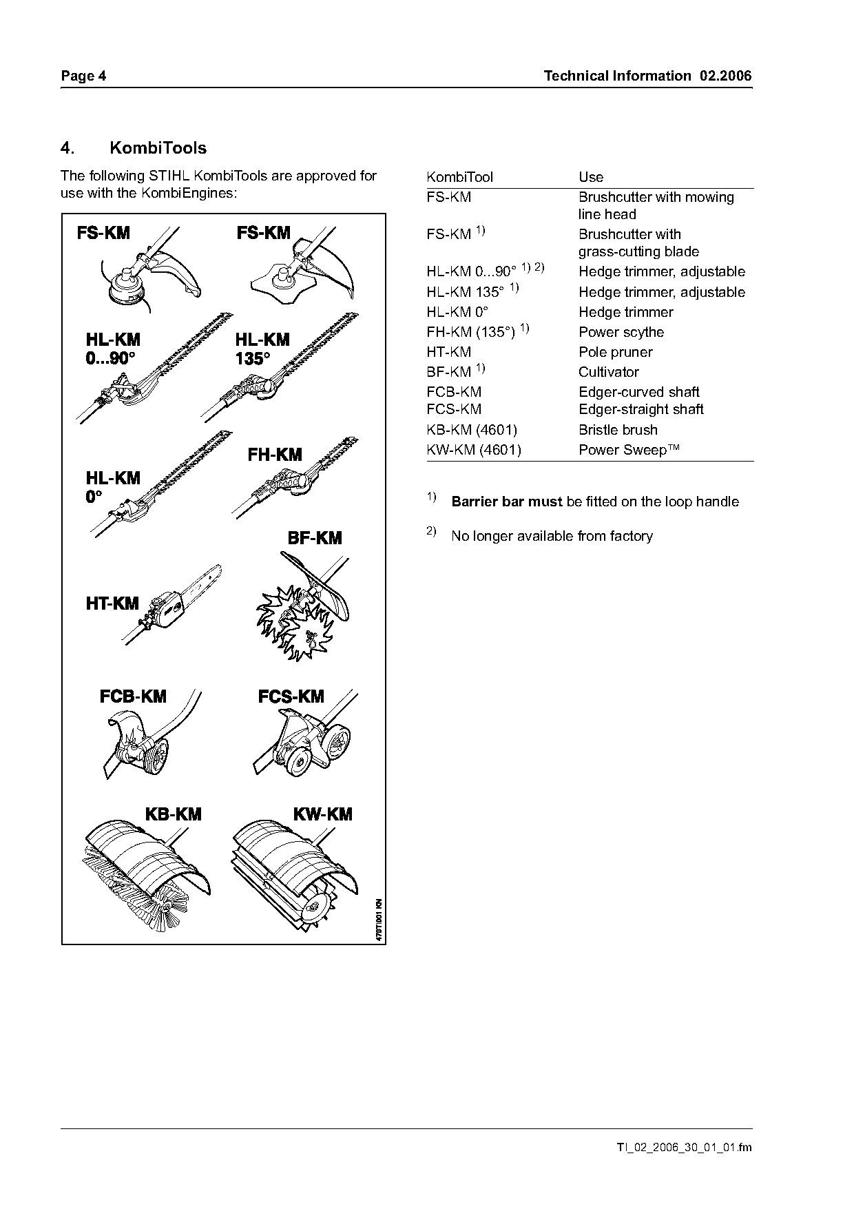
4.       KombiTools
The following STIHL KombiTools are approved for   KombiTool                Use
use with the KombiEngines:                        FS-KM                    Brushcutter with mowing
                                                                           line head
                                                  FS-KM 1)                 Brushcutter with
                                                                           grass-cutting blade
                                                  HL-KM 0...90° 1) 2)      Hedge trimmer, adjustable
                                                  HL-KM 135° 1)            Hedge trimmer, adjustable
                                                  HL-KM 0°                 Hedge trimmer
                                                  FH-KM (135°) 1)          Power scythe
                                                  HT-KM                    Pole pruner
                                                  BF-KM 1)                 Cultivator
                                                  FCB-KM                   Edger-curved shaft
                                                  FCS-KM                   Edger-straight shaft
                                                  KB-KM (4601)             Bristle brush
                                                  KW-KM (4601)             Power Sweep™

                                                  1)
                                                       Barrier bar must be fitted on the loop handle

                                                  2)
                                                       No longer available from factory

                                                                                 TI_02_2006_30_01_01.fm
Page 5 of 8
Text of page 5 — search, copy, screen readers
Technical Information 02.2006                                                                            Page 5

5.      Servicing accessories

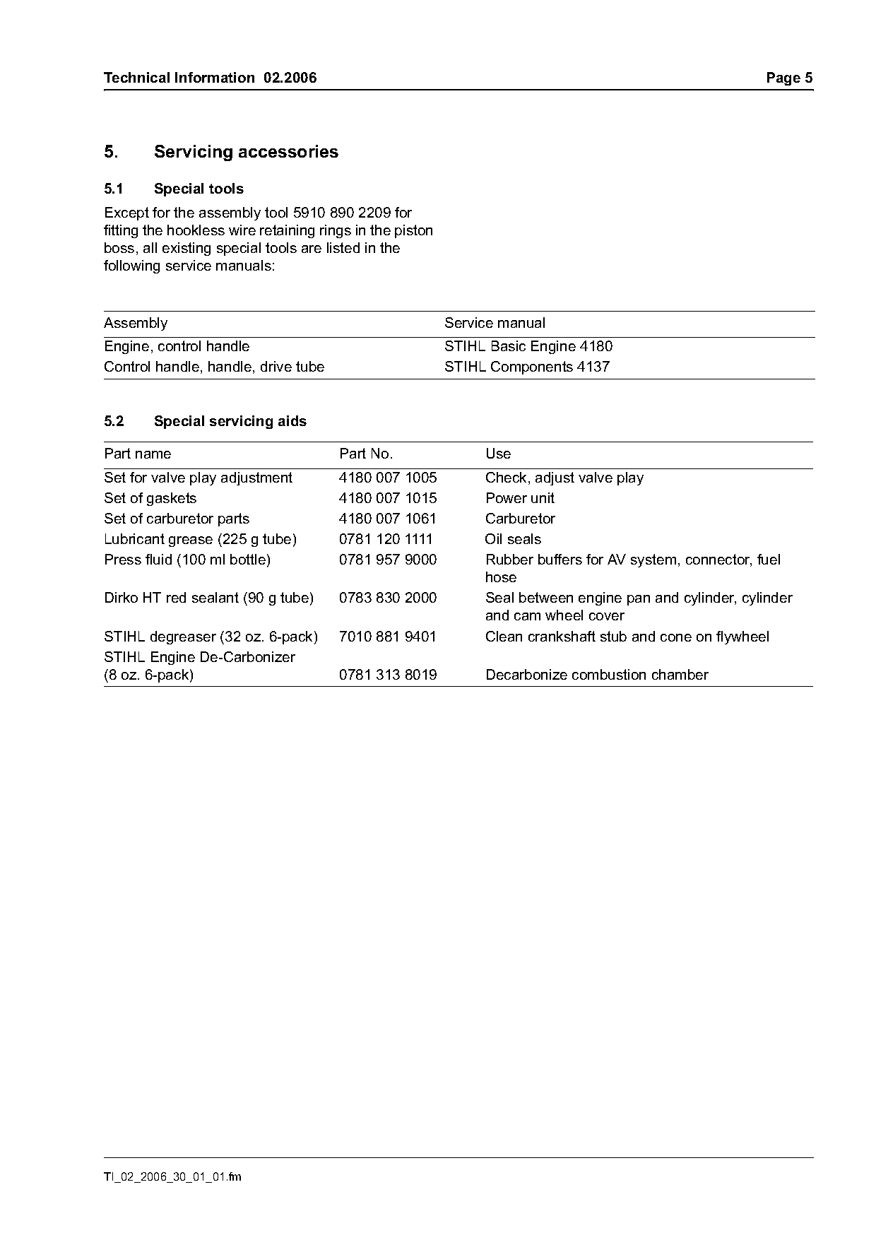
5.1     Special tools
Except for the assembly tool 5910 890 2209 for
fitting the hookless wire retaining rings in the piston
boss, all existing special tools are listed in the
following service manuals:

Assembly                                                  Service manual
Engine, control handle                                    STIHL Basic Engine 4180
Control handle, handle, drive tube                        STIHL Components 4137

5.2     Special servicing aids

Part name                              Part No.                Use
Set for valve play adjustment          4180 007 1005           Check, adjust valve play
Set of gaskets                         4180 007 1015           Power unit
Set of carburetor parts                4180 007 1061           Carburetor
Lubricant grease (225 g tube)          0781 120 1111           Oil seals
Press fluid (100 ml bottle)            0781 957 9000           Rubber buffers for AV system, connector, fuel
                                                               hose
Dirko HT red sealant (90 g tube)       0783 830 2000           Seal between engine pan and cylinder, cylinder
                                                               and cam wheel cover
STIHL degreaser (32 oz. 6-pack)        7010 881 9401           Clean crankshaft stub and cone on flywheel
STIHL Engine De-Carbonizer
(8 oz. 6-pack)                         0781 313 8019           Decarbonize combustion chamber

TI_02_2006_30_01_01.fm
Page 6 of 8
Text of page 6 — search, copy, screen readers
Page 6                                                                   Technical Information 02.2006

6.       Repairs                                       6.2.1   Replace fuel pick-up body

Specific national safety regulations and the safety    The connector must be removed in order to remove
instructions in the instruction manual must be noted   and install the fuel pick-up body.
if the unit has to be started.
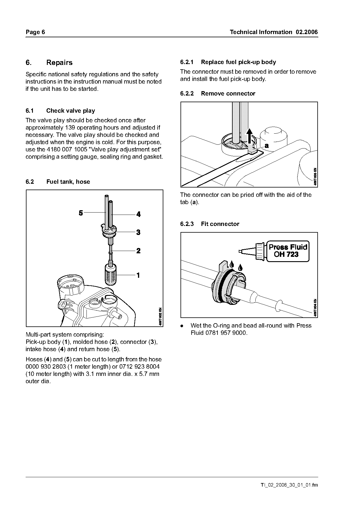
                                                       6.2.2   Remove connector

6.1      Check valve play
The valve play should be checked once after
approximately 139 operating hours and adjusted if
necessary. The valve play should be checked and
adjusted when the engine is cold. For this purpose,
use the 4180 007 1005 "Valve play adjustment set"
comprising a setting gauge, sealing ring and gasket.

6.2      Fuel tank, hose

                                                       The connector can be pried off with the aid of the
                                                       tab (a).

                                                       6.2.3   Fit connector

                                                       .   Wet the O-ring and bead all-round with Press
Multi-part system comprising:                              Fluid 0781 957 9000.
Pick-up body (1), molded hose (2), connector (3),
intake hose (4) and return hose (5).
Hoses (4) and (5) can be cut to length from the hose
0000 930 2803 (1 meter length) or 0712 923 8004
(10 meter length) with 3.1 mm inner dia. x 5.7 mm
outer dia.

                                                                                     TI_02_2006_30_01_01.fm
Page 7 of 8
Text of page 7 — search, copy, screen readers
Technical Information 02.2006                                                                        Page 7

                                                        6.3     Tightening torques
                                                        The tightening torques are specified in the following
                                                        service manuals:

                                                        Assembly                Service manual
                                                        Engine unit,
                                                        control handle          STIHL Basic Engine 4180
                                                        Control handle,
                                                        handle, drive tube      STIHL Components 4137

                                                        6.4     Service manuals
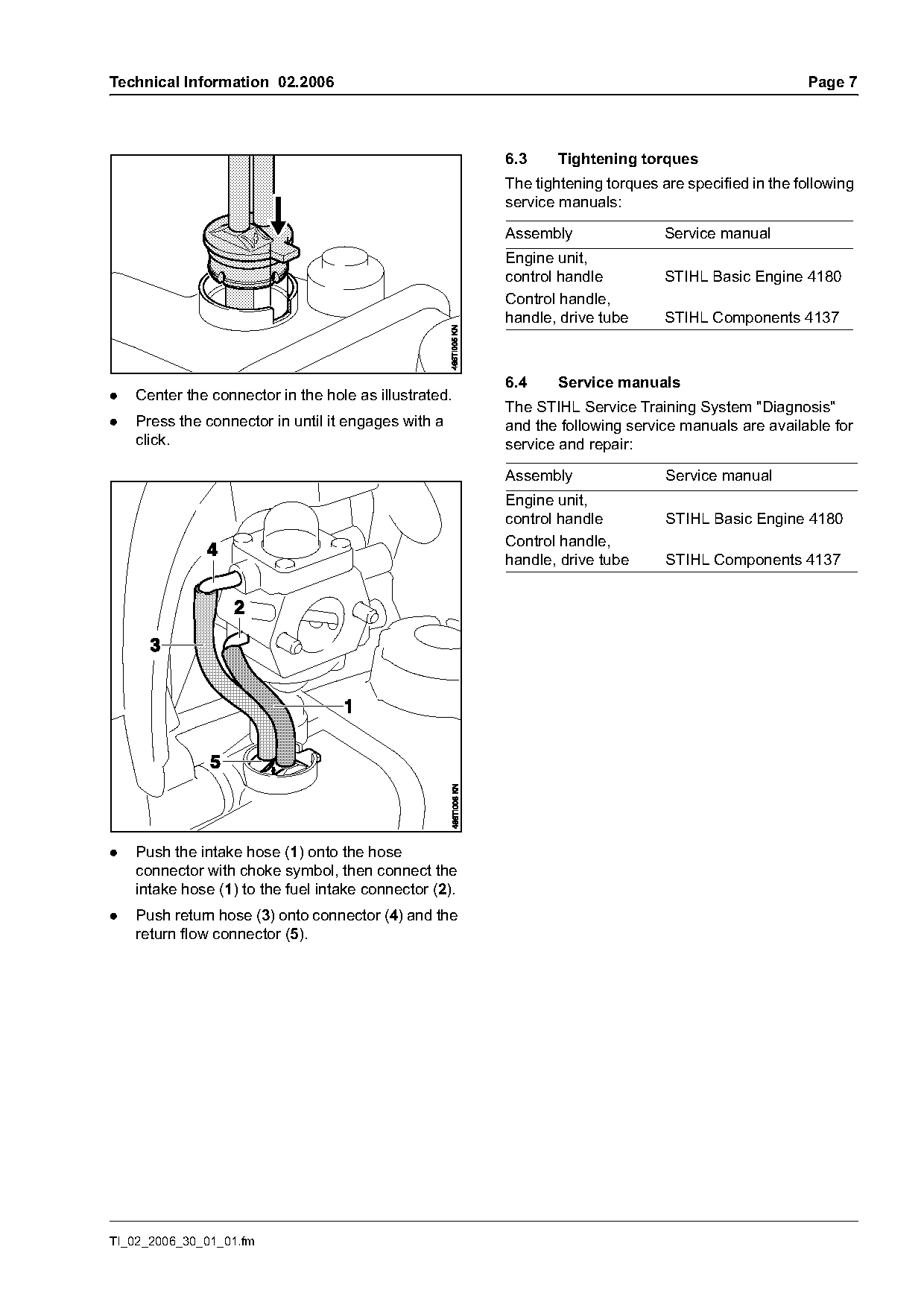
.   Center the connector in the hole as illustrated.
                                                        The STIHL Service Training System "Diagnosis"
.   Press the connector in until it engages with a      and the following service manuals are available for
    click.                                              service and repair:

                                                        Assembly                Service manual
                                                        Engine unit,
                                                        control handle          STIHL Basic Engine 4180
                                                        Control handle,
                                                        handle, drive tube      STIHL Components 4137

.   Push the intake hose (1) onto the hose
    connector with choke symbol, then connect the
    intake hose (1) to the fuel intake connector (2).
.   Push return hose (3) onto connector (4) and the
    return flow connector (5).

TI_02_2006_30_01_01.fm
Page 8 of 8
Text of page 8 — search, copy, screen readers
Page 8                                                              Technical Information 02.2006

6.5      Repair times
The same repair times apply for the KombiEngine
KM 130 R as for the KombiEngine KM 110 R, see
table of repair times for KM 110 R.

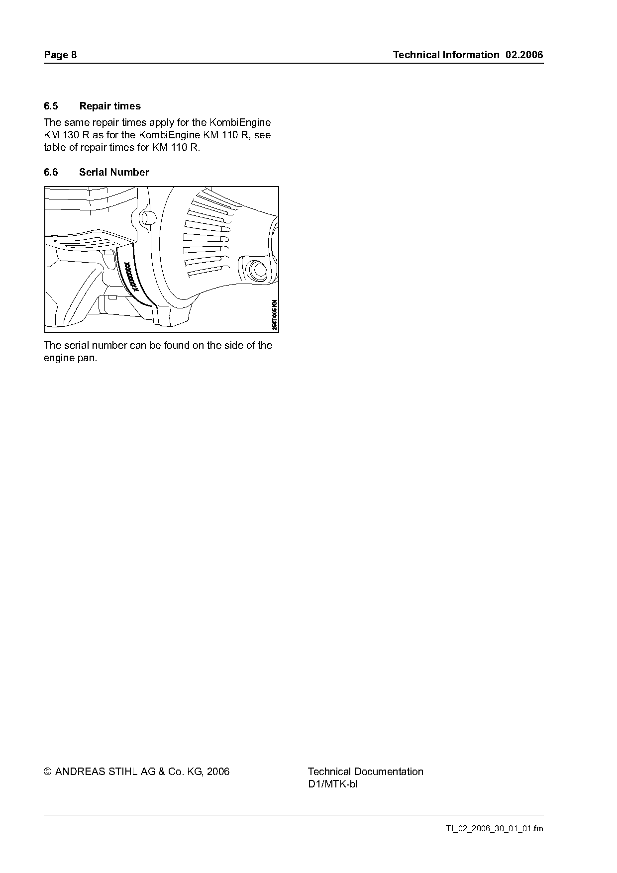
6.6      Serial Number

The serial number can be found on the side of the
engine pan.

© ANDREAS STIHL AG & Co. KG, 2006                   Technical Documentation
                                                    D1/MTK-bl

                                                                              TI_02_2006_30_01_01.fm
Most of these PDFs embed fonts with a shifted character map, so the text above was recovered rather than copied — read it as a faithful but imperfect transcription, and treat the page image above each block as the authority where the two disagree — the figures exist only there, because they are vector drawings that text extraction cannot keep.