Technical Information · issue 6 of 2006
Ignition system (ignition module, flywheel); Tank housing (tank vent, hose, routing / switch); Summary; Service note (adjustment of air shutter linkage)
IssueTI 6/2006
Part changes (1)
| Was | Becomes | What the bulletin says |
|---|---|---|
| 4224 350 0804 | 4224 350 0809 | Great care The previous tank housing 4224 350 0804 has been must therefore be taken to establish which ignition replaced by version 4224 350 0809 in conjunction system has been installed when carrying out with the individual changes described below. |
Full text
Page 1 of 6
Text of page 1 — search, copy, screen readers
STIH)

Technical Information                                                                           06.2006

  Cut-off machines STIHL TS 700, TS 800                             – Series 4224

  Contents
  1.    Ignition system (ignition module, flywheel)
  2.    Tank housing (tank vent, hose, routing / switch)
  3.    Summary
  4.    Service note (adjustment of air shutter linkage)

  1.       Ignition system (ignition module,
           flywheel)
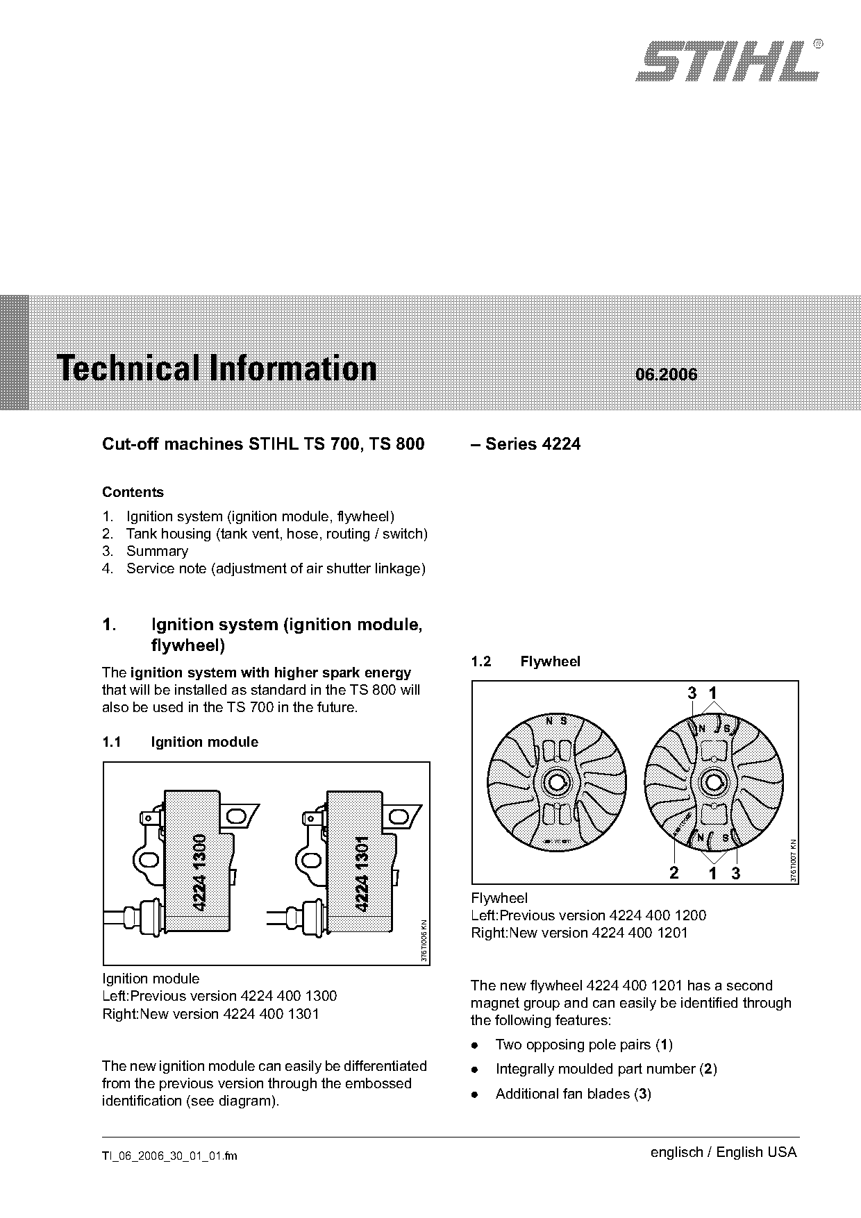
                                                                    1.2      Flywheel
  The ignition system with higher spark energy
  that will be installed as standard in the TS 800 will                                                   3 1
  also be used in the TS 700 in the future.

  1.1      Ignition module

                                                                                                                      376TI007 KN

                                                                                                      2     1 3
                                                                    Flywheel
                                                                    Left:Previous version 4224 400 1200
                                                      376TI006 KN

                                                                    Right:New version 4224 400 1201

  Ignition module                                                   The new flywheel 4224 400 1201 has a second
  Left:Previous version 4224 400 1300                               magnet group and can easily be identified through
  Right:New version 4224 400 1301                                   the following features:
                                                                    .     Two opposing pole pairs (1)
  The new ignition module can easily be differentiated              .     Integrally moulded part number (2)
  from the previous version through the embossed
                                                                    .     Additional fan blades (3)
  identification (see diagram).

  TI_06_2006_30_01_01.fm                                                                          englisch / English USA
Page 2 of 6
Text of page 2 — search, copy, screen readers
Page 2                                                                      Technical Information 06.2006

1.3      Spare parts / service notes                     2.     Tank housing (tank vent, hose,
The new ignition system will not be introduced in all           routing / switch)
versions of the TS 700 at the same time. Great care
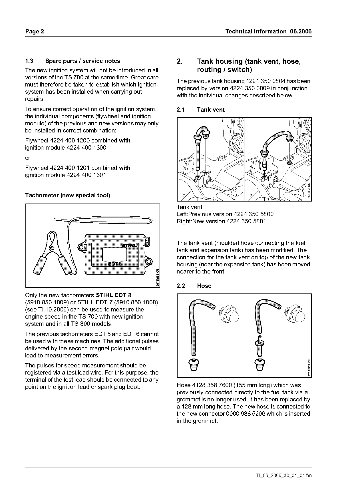
                                                         The previous tank housing 4224 350 0804 has been
must therefore be taken to establish which ignition
                                                         replaced by version 4224 350 0809 in conjunction
system has been installed when carrying out
                                                         with the individual changes described below.
repairs.
To ensure correct operation of the ignition system,      2.1    Tank vent
the individual components (flywheel and ignition
module) of the previous and new versions may only
be installed in correct combination:
Flywheel 4224 400 1200 combined with
ignition module 4224 400 1300
Flywheel 4224 400 1201 combined with
ignition module 4224 400 1301

                                                                                                           376TI008 KN
Tachometer (new special tool)
                                                         Tank vent
                                                         Left:Previous version 4224 350 5800
                                                         Right:New version 4224 350 5801

                                                         The tank vent (moulded hose connecting the fuel
                                                         tank and expansion tank) has been modified. The
                                                         connection for the tank vent on top of the new tank
                                                         housing (near the expansion tank) has been moved
                                                         nearer to the front.

                                                         2.2    Hose
Only the new tachometers STIHL EDT 8
(5910 850 1009) or STIHL EDT 7 (5910 850 1008)
(see TI 10.2006) can be used to measure the
engine speed in the TS 700 with new ignition
system and in all TS 800 models.
The previous tachometers EDT 5 and EDT 6 cannot
be used with these machines. The additional pulses
delivered by the second magnet pole pair would
lead to measurement errors.
                                                                                                            376TI009 KN

The pulses for speed measurement should be
registered via a test lead wire. For this purpose, the
terminal of the test lead should be connected to any
point on the ignition lead or spark plug boot.           Hose 4128 358 7600 (155 mm long) which was
                                                         previously connected directly to the fuel tank via a
                                                         grommet is no longer used. It has been replaced by
                                                         a 128 mm long hose. The new hose is connected to
                                                         the new connector 0000 988 5206 which is inserted
                                                         in the grommet.

                                                                                       TI_06_2006_30_01_01.fm
Page 3 of 6
Text of page 3 — search, copy, screen readers
Technical Information 06.2006                                                                             Page 3

The new hose is available in one meter lengths for         2.4     Service notes
replacement (0000 930 2802) and must be cut to             The tank vent 4224 350 5800 and switch
128 mm (5 in.) when required.                              4224 430 0500 cannot be replaced and remain
                                                           available for repairs to the previous tank housing.
2.3    Routing / switch
                                                           The previous and new tank vents are of different
The guide ribs integrally moulded onto the tank            colors. The previous version is made of black
housing to secure the short-circuit and ground wires       material, the new version of green material.
have been spaced more closely. At the same time,
the short-circuit and ground wires (on switch              The hose (128 mm-5 in.) with connector
4224 430 0500) are no longer encased in a hose,            0000 988 5206 must be used as replacement for
but now take the form of a light plastic-sheathed          the hose 4128 358 7600.
cable. The switch now has the part number                  The previous and new switches differ with regard to
4224 430 0501.                                             the color of the short-circuit and ground wires: in the
                                                           previous switch, these wires were blue / black, in the
                                                           new switch they are brown / blue.

3.     Summary
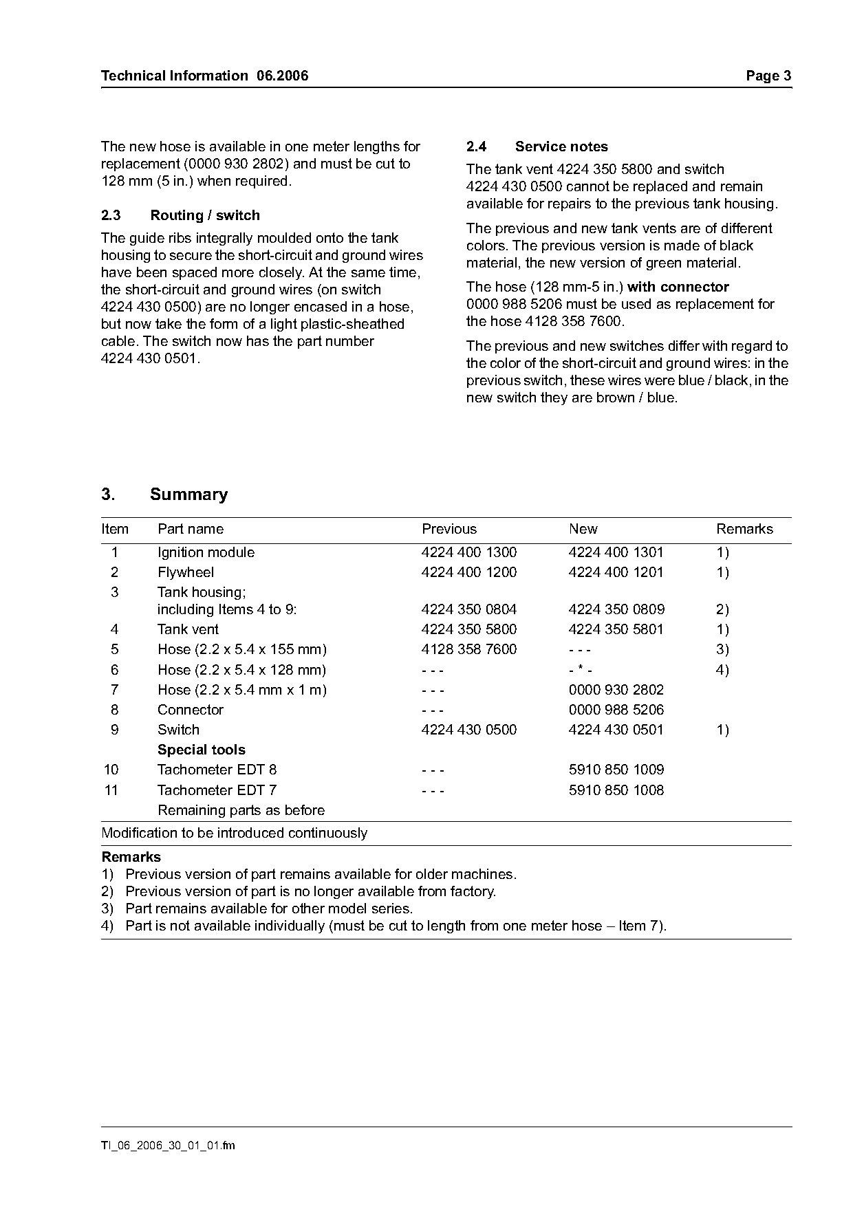
Item     Part name                                   Previous               New                      Remarks
 1       Ignition module                             4224 400 1300          4224 400 1301            1)
 2       Flywheel                                    4224 400 1200          4224 400 1201            1)
 3       Tank housing;
         including Items 4 to 9:                     4224 350 0804          4224 350 0809            2)
 4       Tank vent                                   4224 350 5800          4224 350 5801            1)
 5       Hose (2.2 x 5.4 x 155 mm)                   4128 358 7600          ---                      3)
 6       Hose (2.2 x 5.4 x 128 mm)                   ---                    -*-                      4)
 7       Hose (2.2 x 5.4 mm x 1 m)                   ---                    0000 930 2802
 8       Connector                                   ---                    0000 988 5206
 9       Switch                                      4224 430 0500          4224 430 0501            1)
         Special tools
10       Tachometer EDT 8                            ---                    5910 850 1009
11       Tachometer EDT 7                            ---                    5910 850 1008
         Remaining parts as before
Modification to be introduced continuously
Remarks
1) Previous version of part remains available for older machines.
2) Previous version of part is no longer available from factory.
3) Part remains available for other model series.
4) Part is not available individually (must be cut to length from one meter hose – Item 7).

TI_06_2006_30_01_01.fm
Page 4 of 6
Text of page 4 — search, copy, screen readers
Page 4                                                                                   Technical Information 06.2006

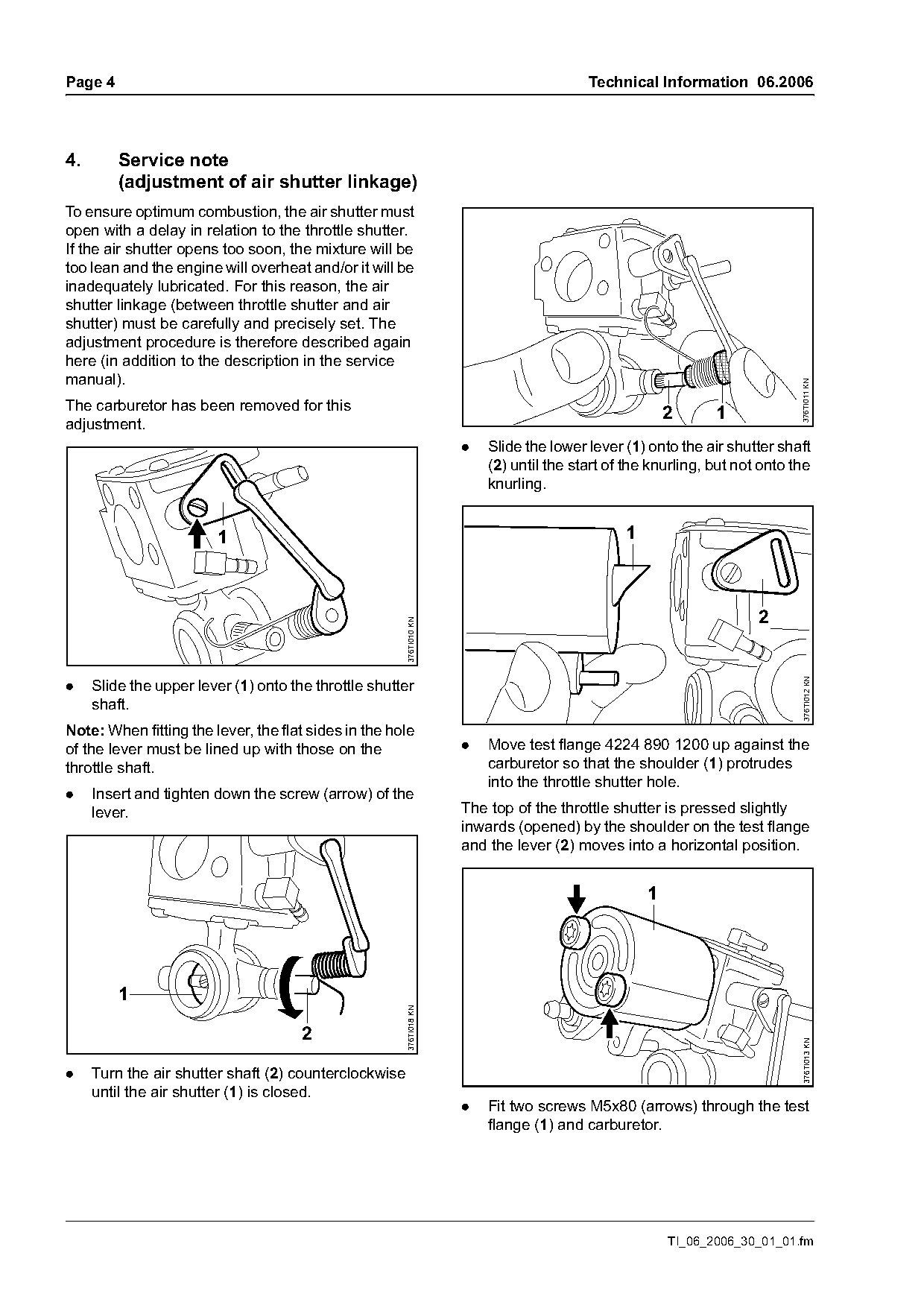
4.       Service note
         (adjustment of air shutter linkage)
To ensure optimum combustion, the air shutter must
open with a delay in relation to the throttle shutter.
If the air shutter opens too soon, the mixture will be
too lean and the engine will overheat and/or it will be
inadequately lubricated. For this reason, the air
shutter linkage (between throttle shutter and air
shutter) must be carefully and precisely set. The
adjustment procedure is therefore described again
here (in addition to the description in the service
manual).

                                                                                                                            376TI011 KN
The carburetor has been removed for this
                                                                                                       2      1
adjustment.
                                                                     .   Slide the lower lever (1) onto the air shutter shaft
                                                                         (2) until the start of the knurling, but not onto the
                                                                         knurling.

                        1                                                                      1

                                                                                                                     2
                                                       376TI010 KN

                                                                                                                            376TI012 KN
.    Slide the upper lever (1) onto the throttle shutter
     shaft.
Note: When fitting the lever, the flat sides in the hole
of the lever must be lined up with those on the                      .   Move test flange 4224 890 1200 up against the
throttle shaft.                                                          carburetor so that the shoulder (1) protrudes
                                                                         into the throttle shutter hole.
.    Insert and tighten down the screw (arrow) of the
     lever.                                                          The top of the throttle shutter is pressed slightly
                                                                     inwards (opened) by the shoulder on the test flange
                                                                     and the lever (2) moves into a horizontal position.


         1
                                                       376TI018 KN

                                      2
                                                                                                                            376TI013 KN

.    Turn the air shutter shaft (2) counterclockwise
     until the air shutter (1) is closed.
                                                                     .   Fit two screws M5x80 (arrows) through the test
                                                                         flange (1) and carburetor.

                                                                                                       TI_06_2006_30_01_01.fm
Page 5 of 6
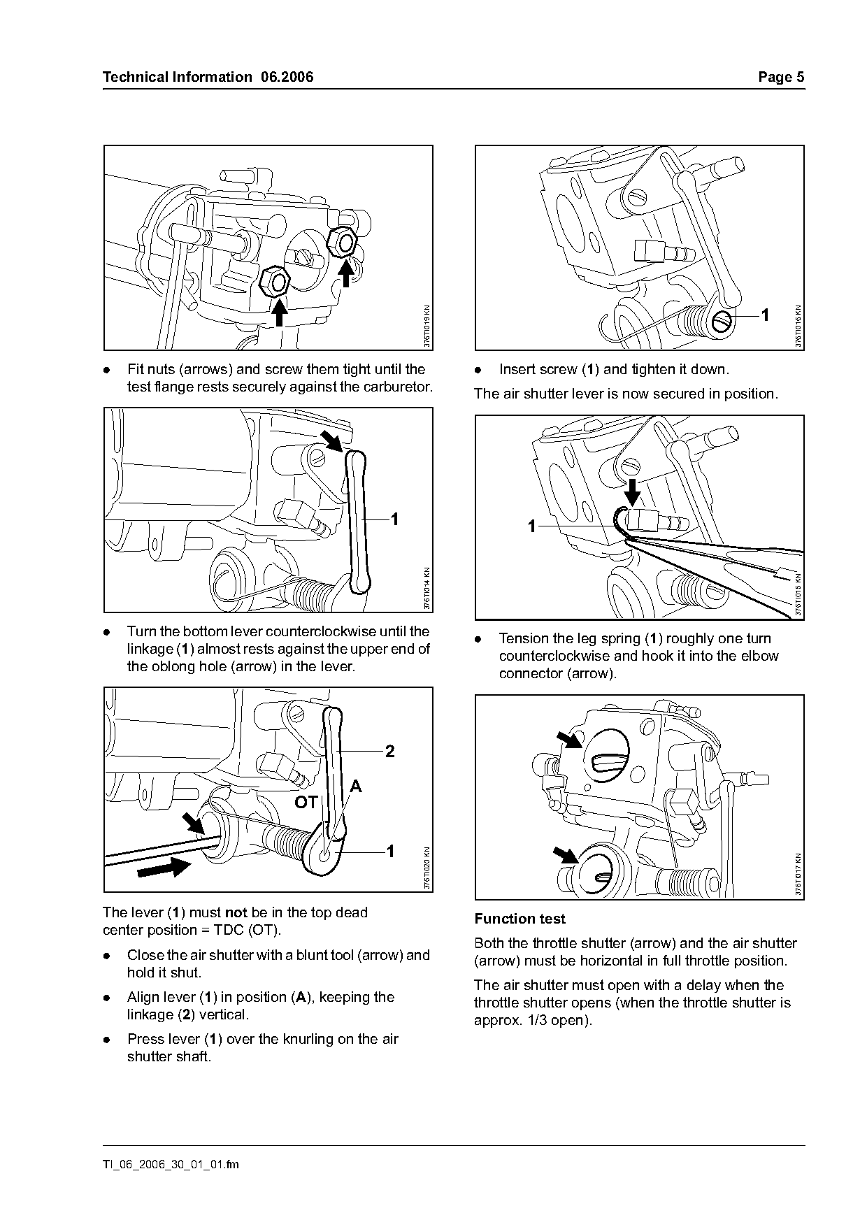
Text of page 5 — search, copy, screen readers
Technical Information 06.2006                                                                                    Page 5

                                                     376TI019 KN

                                                                                                                          376TI016 KN
                                                                                                                  1

.   Fit nuts (arrows) and screw them tight until the               .   Insert screw (1) and tighten it down.
    test flange rests securely against the carburetor.             The air shutter lever is now secured in position.

                                                1                          1
                                                     376TI014 KN

                                                                                                                          376TI015 KN
.   Turn the bottom lever counterclockwise until the
                                                                   .   Tension the leg spring (1) roughly one turn
    linkage (1) almost rests against the upper end of
                                                                       counterclockwise and hook it into the elbow
    the oblong hole (arrow) in the lever.
                                                                       connector (arrow).


                                               1
                                                     376TI020 KN

                                                                                                                          376TI017 KN

The lever (1) must not be in the top dead                          Function test
center position = TDC (OT).
                                                                   Both the throttle shutter (arrow) and the air shutter
.   Close the air shutter with a blunt tool (arrow) and            (arrow) must be horizontal in full throttle position.
    hold it shut.
                                                                   The air shutter must open with a delay when the
.   Align lever (1) in position (A), keeping the                   throttle shutter opens (when the throttle shutter is
    linkage (2) vertical.                                          approx. 1/3 open).
.   Press lever (1) over the knurling on the air
    shutter shaft.

TI_06_2006_30_01_01.fm
Page 6 of 6

Text of page 6 — search, copy, screen readers
Page 6                                                                  Technical Information 06.2006

Last Technical Information on the STIHL TS 700, TS 800: 52.2004 (TS 700), 01.2006 (TS 800)

© ANDREAS STIHL AG & Co. KG, 10. May 2006              Technical Documentation
                                                       D1/MTK-sc

                                                                                   TI_06_2006_30_01_01.fm
Most of these PDFs embed fonts with a shifted character map, so the text above was recovered rather than copied — read it as a faithful but imperfect transcription, and treat the page image above each block as the authority where the two disagree — the figures exist only there, because they are vector drawings that text extraction cannot keep.