Technical Information · issue 10 of 2006
New tachometers EDT 7 and EDT 8; New ignition systems; Tachometer EDT 7; Tachometer EDT 8; Antennas supplied with the units; Method; Battery life; Pictograms in the supplement for the EDT 8; Hour meter; Summary
IssueTI 10/2006
Full text
Page 1 of 5
Text of page 1 — search, copy, screen readers
STIH)

Technical Information                                                            10.2006

  New STIHL special tools

  Contents
  1. New tachometers EDT 7 and EDT 8
     1.1 New ignition systems
     1.2 Tachometer EDT 7
     1.3 Tachometer EDT 8
     1.4 Antennas supplied with the units
     1.5 Method
     1.6 Battery life
     1.7 Pictograms in the supplement for the EDT 8
     1.8 Hour meter
     1.9 Summary

  1.     New tachometers EDT 7 and
         EDT 8

  1.1    New ignition systems
                                                       The development of new ignition systems has made
                                                       it necessary to use new tachometers.
                                                       The principle of operation underlying the new
                                                       ignition systems is different from that of the
                                                       "standard" ignition system.
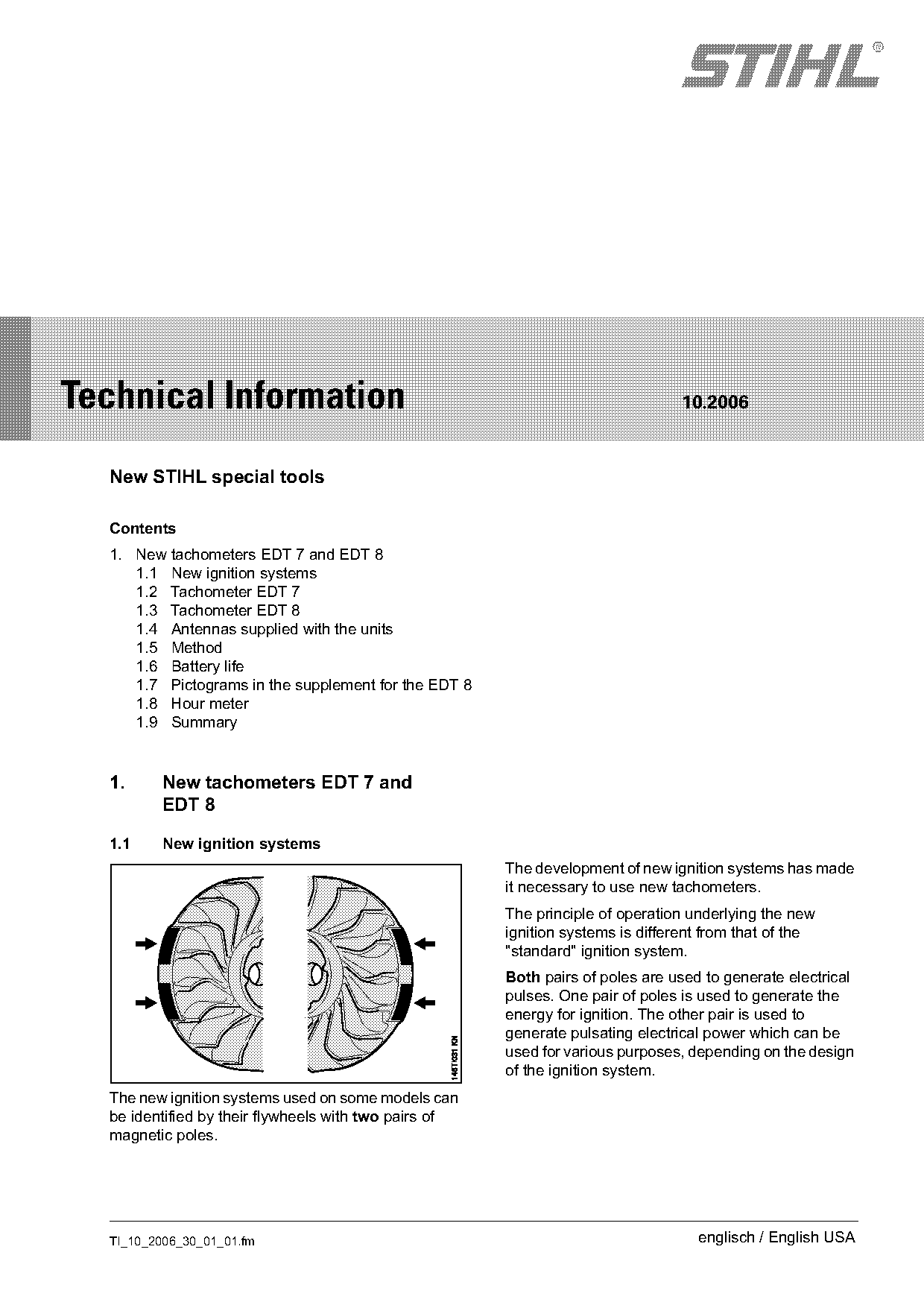
                                                       Both pairs of poles are used to generate electrical
                                                       pulses. One pair of poles is used to generate the
                                                       energy for ignition. The other pair is used to
                                                       generate pulsating electrical power which can be
                                                       used for various purposes, depending on the design
                                                       of the ignition system.
  The new ignition systems used on some models can
  be identified by their flywheels with two pairs of
  magnetic poles.

  TI_10_2006_30_01_01.fm                                                           englisch / English USA
Page 2 of 5
Text of page 2 — search, copy, screen readers
Page 2                                                                                 Technical Information 10.2006

The second pair of poles generates a relatively high              Features of the EDT 7:
impulse voltage which is registered by the
                                                                  -     Used for engines with one cylinder
tachometer and used for indication of the speed,
depending on the instrument's electrical design.                  -     Used with two-stroke and four-stroke engines
This means that, for every revolution of the flywheel,                  with one ignition pulse for each revolution of the
the tachometer can indicate two revolutions of the                      crankshaft. Can be adjusted for one pulse per
power unit, which effectively constitutes a                             two revolutions.
measuring error.                                                  -     Storage and indication of the maximum speed
The new tachometers are designed and built in such                -     Operation and adjustment of settings via a
a way that they only process and indicate the                           single button
ignition pulses of the new ignition systems.
                                                                  Operation of the EDT 7 is described in a manual
The purposes for which the second electrical pulse                supplied with the unit.
is used are described in the Technical Information
bulletins issued when a power tool with newly                     The previous tachometer EDT 5 can continue to be
developed ignition system is launched on the                      used for "standard" STIHL ignition systems.
market.

                                                                  1.3       Tachometer EDT 8
1.2      Tachometer EDT 7

                                                                                                                        901TI050 KN
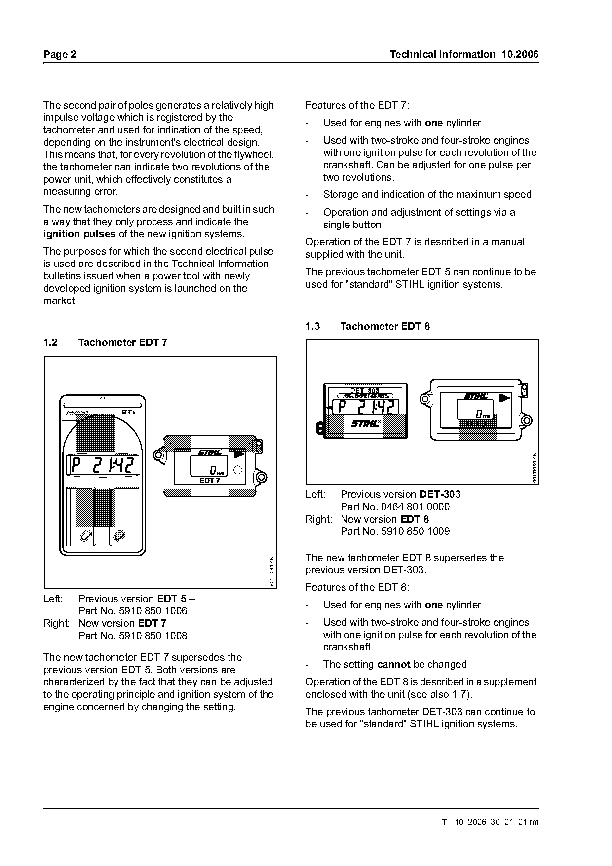
                                                                  Left:  Previous version DET-303 –
                                                                         Part No. 0464 801 0000
                                                                  Right: New version EDT 8 –
                                                                         Part No. 5910 850 1009

                                                                  The new tachometer EDT 8 supersedes the
                                                    901TI041 KN

                                                                  previous version DET-303.
                                                                  Features of the EDT 8:
Left:  Previous version EDT 5 –
                                                                  -     Used for engines with one cylinder
       Part No. 5910 850 1006
Right: New version EDT 7 –                                        -     Used with two-stroke and four-stroke engines
       Part No. 5910 850 1008                                           with one ignition pulse for each revolution of the
                                                                        crankshaft
The new tachometer EDT 7 supersedes the
                                                                  -     The setting cannot be changed
previous version EDT 5. Both versions are
characterized by the fact that they can be adjusted               Operation of the EDT 8 is described in a supplement
to the operating principle and ignition system of the             enclosed with the unit (see also 1.7).
engine concerned by changing the setting.                         The previous tachometer DET-303 can continue to
                                                                  be used for "standard" STIHL ignition systems.

                                                                                                   TI_10_2006_30_01_01.fm
Page 3 of 5
Text of page 3 — search, copy, screen readers
Technical Information 10.2006                                                                                        Page 3

1.4       Antennas supplied with the units                          1.5       Method

                                                                    1.5.1     Measurement with test line


                                                     901TI043 KN
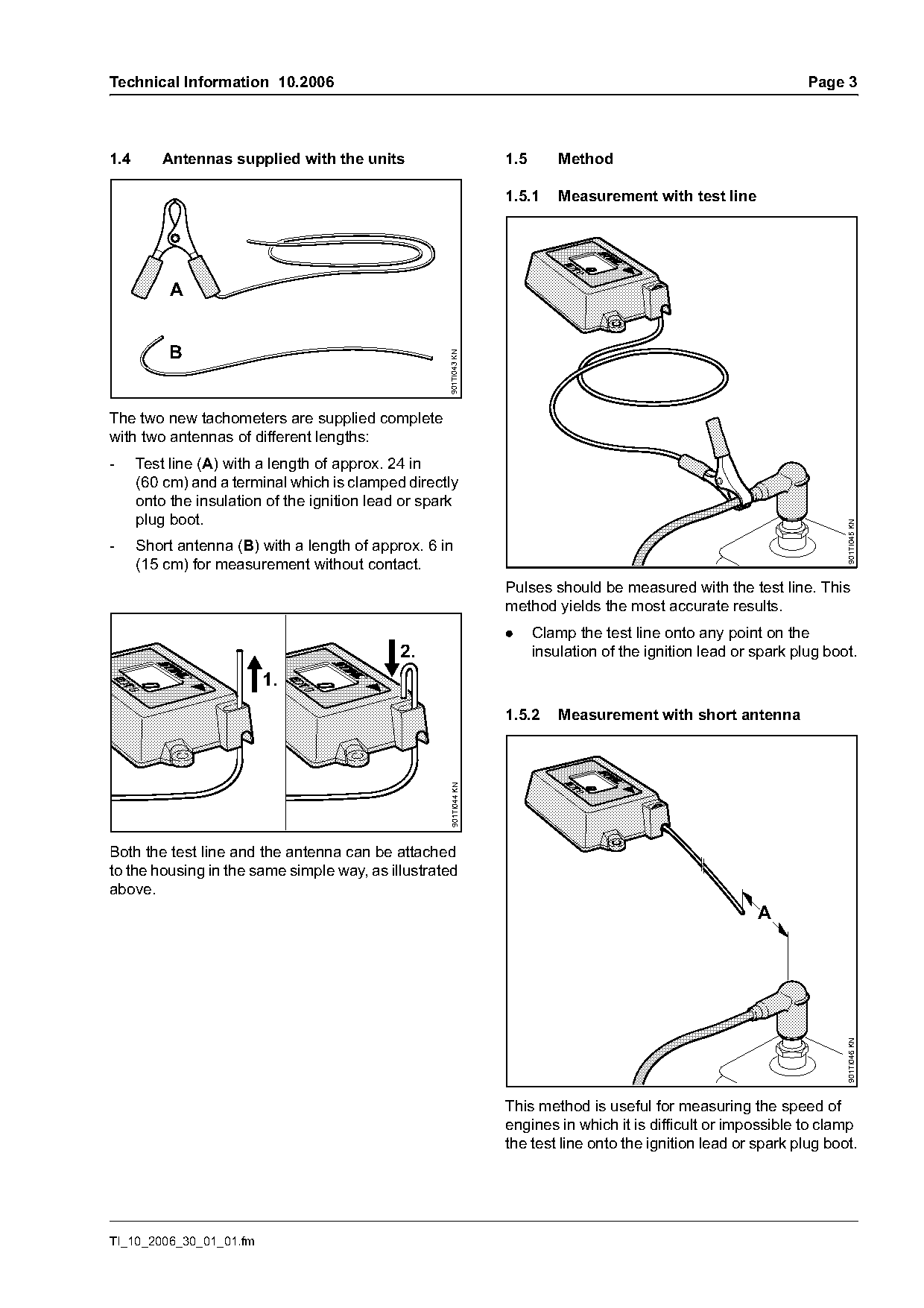
The two new tachometers are supplied complete
with two antennas of different lengths:
-     Test line (A) with a length of approx. 24 in
      (60 cm) and a terminal which is clamped directly
      onto the insulation of the ignition lead or spark
      plug boot.

                                                                                                                           901TI045 KN
-     Short antenna (B) with a length of approx. 6 in
      (15 cm) for measurement without contact.
                                                                    Pulses should be measured with the test line. This
                                                                    method yields the most accurate results.
                                                                    .     Clamp the test line onto any point on the
                                              2.                          insulation of the ignition lead or spark plug boot.
                         1.
                                                                    1.5.2     Measurement with short antenna
                                                      901TI044 KN

Both the test line and the antenna can be attached
to the housing in the same simple way, as illustrated
above.
                                                                                                             A
                                                                                                                           901TI046 KN

                                                                    This method is useful for measuring the speed of
                                                                    engines in which it is difficult or impossible to clamp
                                                                    the test line onto the ignition lead or spark plug boot.

TI_10_2006_30_01_01.fm
Page 4 of 5
Text of page 4 — search, copy, screen readers
Page 4                                                                               Technical Information 10.2006

During measurement:                                             1.6       Battery life
.   Ensure that distance (A) remains between                    The battery in the two new tachometers cannot be
    4 and 8 in (10 and 20 cm).                                  replaced. The battery has a service life of
                                                                approximately ten years in normal use.
.   Direct the antenna towards the pulse-
    conducting parts of the ignition system.
Steady indication of the speed on the display means
                                                                1.7       Pictograms in the supplement for the
that the tachometer is properly aligned.
                                                                          EDT 8
                                                                Operation, the essential technical data and the
                                                                unit's use are explained by means of drawings and
1.5.3    Measurement with built-in antenna                      pictograms in the supplement enclosed with the
                                                                EDT 8.

                   B                                            1.7.1     Explanation of pictograms
                                                                Use

                                                                          A                B               C
                                                  901TI047 KN

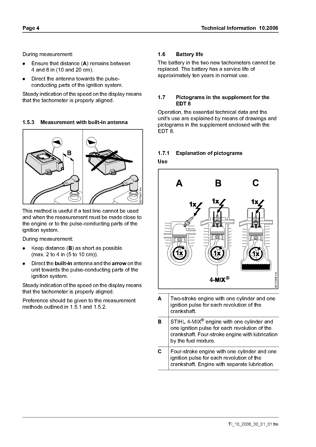
This method is useful if a test line cannot be used
and when the measurement must be made close to
the engine or to the pulse-conducting parts of the
ignition system.
During measurement:
.   Keep distance (B) as short as possible
    (max. 2 to 4 in (5 to 10 cm)).
.   Direct the built-in antenna and the arrow on the
    unit towards the pulse-conducting parts of the
                                                                                                                     901TI048 KN
    ignition system.
Steady indication of the speed on the display means
that the tachometer is properly aligned.
Preference should be given to the measurement                   A       Two-stroke engine with one cylinder and one
methods outlined in 1.5.1 and 1.5.2.                                    ignition pulse for each revolution of the
                                                                        crankshaft.

                                                                B       STIHL 4-MIX® engine with one cylinder and
                                                                        one ignition pulse for each revolution of the
                                                                        crankshaft. Four-stroke engine with lubrication
                                                                        by the fuel mixture.

                                                                C       Four-stroke engine with one cylinder and one
                                                                        ignition pulse for each revolution of the
                                                                        crankshaft. Engine with separate lubrication.

                                                                                                 TI_10_2006_30_01_01.fm
Page 5 of 5
Text of page 5 — search, copy, screen readers
Technical Information 10.2006                                                                Page 5

Technical data

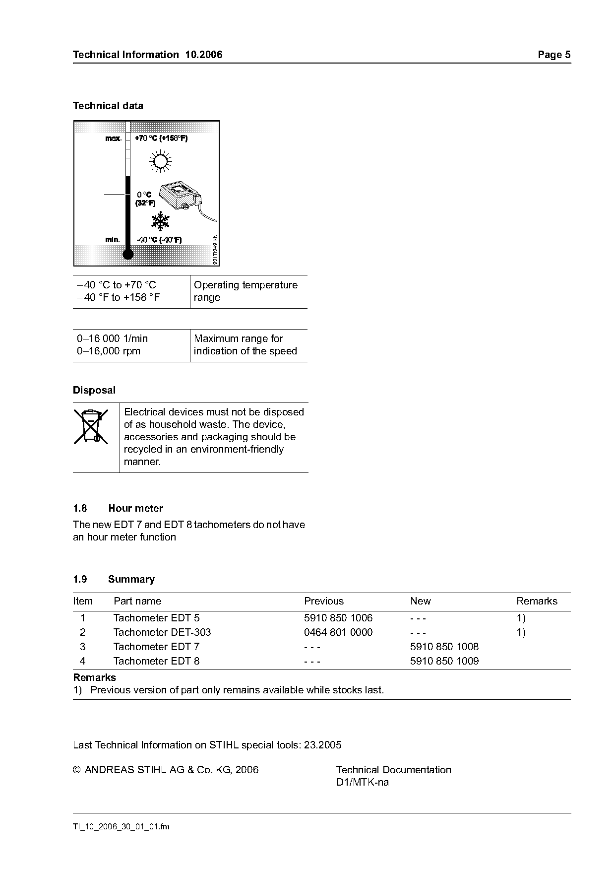
                              901TI049 KN

– 40 °C to +70 °C         Operating temperature
– 40 °F to +158 °F        range

0–16 000 1/min            Maximum range for
0–16,000 rpm              indication of the speed

Disposal

           Electrical devices must not be disposed
           of as household waste. The device,
           accessories and packaging should be
           recycled in an environment-friendly
           manner.

1.8    Hour meter
The new EDT 7 and EDT 8 tachometers do not have
an hour meter function

1.9    Summary

Item     Part name                                  Previous            New             Remarks
 1       Tachometer EDT 5                           5910 850 1006       ---             1)
 2       Tachometer DET-303                         0464 801 0000       ---             1)
 3       Tachometer EDT 7                           ---                 5910 850 1008
 4       Tachometer EDT 8                           ---                 5910 850 1009
Remarks
1) Previous version of part only remains available while stocks last.

Last Technical lnformation on STIHL special tools: 23.2005

© ANDREAS STIHL AG & Co. KG, 2006                         Technical Documentation
                                                          D1/MTK-na

TI_10_2006_30_01_01.fm
Most of these PDFs embed fonts with a shifted character map, so the text above was recovered rather than copied — read it as a faithful but imperfect transcription, and treat the page image above each block as the authority where the two disagree — the figures exist only there, because they are vector drawings that text extraction cannot keep.