Technical Information · issue 32 of 2006
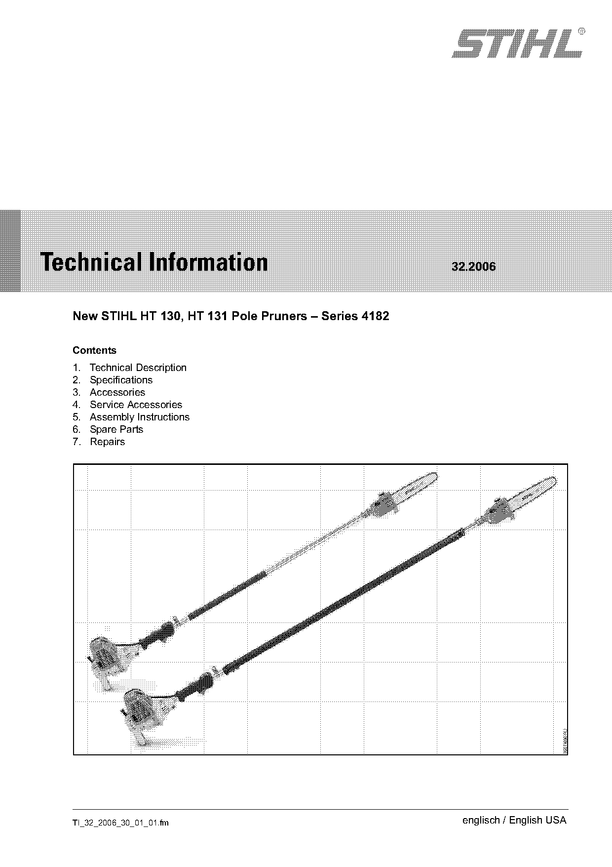
New STIHL HT 130, HT 131 Pole Pruners
IssueTI 32/2006
Full text
Page 1 of 12
Text of page 1 — search, copy, screen readers
STIH)

Technical Information                                   32.2006

  New STIHL HT 130, HT 131 Pole Pruners – Series 4182

  Contents
  1.   Technical Description
  2.   Specifications
  3.   Accessories
  4.   Service Accessories
  5.   Assembly Instructions
  6.   Spare Parts
  7.   Repairs

  TI_32_2006_30_01_01.fm                                 englisch / English USA
Page 2 of 12
Text of page 2 — search, copy, screen readers
Page 2                                                                        Technical Information 32.2006

The new HT 130 and HT 131 pole pruners with the          1.4     Drive Tube
STIHL 4-MIX® engine further extend the line of pole      HT 130 drive tube
pruners for pruning and tending trees.
                                                         .     Drive tube with a flexible drive shaft supported in
New units feature high chain speed and high torque.            a liner reduces vibrations and produces a
The HT 130 is equipped with a fixed drive tube,                smoother cut.
while the HT 131 features a telescopic drive tube        .     Maximum reach: 11'5" (3.5 m)
that can be adjusted to suit different applications.
                                                         HT 131 telescopic drive tube
Applications are the same as those of model HT 100
                                                         .     Extendable drive tube with a shaft supported in
and HT 101 pole pruners.
                                                               a liner and ball bearings.

1.        Technical Description                          .     Maximum reach: 16 ft. (5.0 m)
                                                         .     Improved telescopic drive shaft components
The powerhead and controls are the same as those
of the FS 130 R brushcutter.
.     Much higher chain speed for smoother cutting
      performance                                        2.        Specifications
                      ®
.     Powerful 4-MIX engine with high torque
                                                         2.1       Engine
                     ®                                   STIHL single cylinder four-stroke engine with gas-
1.1     STIHL 4-MIX Engine
                                                         oil lubrication
.     Familiar fuel mix
                                                         Displacement:             2.2 cu.in (36.3 cm3)
.     Favorable fuel consumption
                                                         Bore:                     1.69 in (43 mm)
.     Operates in all positions                          Stroke:                   0.98 in (25 mm)
.     Reduced emissions                                  Engine power to
                                                         ISO 8893:                 1.90 bhp (1.4 kW )
.     Good acceleration
                                                         Idle speed:               2,800 rpm
.     Compact construction – attractive design
                                                         Rewind starter:           Single pawl system
.     Favorable power-to-weight ratio                    Starter rope:             Diameter 0.120 in,
.     Simple maintenance – service-friendly                                        33.5 in long
                                                                                   (Diameter 3.0 mm,
.     Lower vibrations                                                             850 mm long)
.     Reduced cranking effort                            Clutch engages at:        3,700 rpm
                                                         Cut-off speed range
1.2     Tank Cap                                         without cutting
.     The tank cap features a hinged grip designed for   attachment
      quick and simple opening and closing.              (chain sprocket):         10,500 +/- 200 rpm
                                                         Valve clearance
1.3     Controls                                         Inlet:                    0.004 in (0.10 mm)
.     Ergonomic control handle with comfortable grip     Exhaust:                  0.004 in (0.10 mm)
      zone.
                                                         2.2       Ignition System
.     Control handle with integral throttle cable
      adjuster.                                          Ignition module:             with integral electronic
                                                                                      speed governor
                                                         Spark plug
                                                         (suppressed):                NGK CMR6H
                                                         Electrode gap:               0.020 in (0.5 mm)

                                                                                           TI_32_2006_30_01_01.fm
Page 3 of 12
Text of page 3 — search, copy, screen readers
Technical Information 32.2006                                                                           Page 3

2.3   Fuel System                                          2.5    Length (with cutting attachment)
The STIHL 4-MIX® engine features gasoline-oil              HT 130                  approx. 84.6 in (215 cm)
lubrication and must be run on a fuel mixture of           HT 131 (drive tube      approx. 106 in (270 cm)
gasoline and air cooled two-cycle engine mix oil.          compressed)
STIHL HP Ultra synthetic mix oil is ideal for use in all   HT 131 (drive tube      approx. 153.5 in (390 cm)
STIHL engines.                                             extended)
Fuel:
                                                           2.6    Weight
see instruction manual
                                                           without cutting attachment
                                                           HT 130:                      12.6 lbs. (5.7 kg)
Carburetor:                                                HT 131:                      17.2 lbs. (7.8 kg)
All position diaphragm carburetor with integral fuel
pump.
For carburetor adjustment see TI 41.2004.
                                                           3.     Accessories
Low speed screw L
(standard setting with caps): Open 3/4 turn (no
                              further than stop)

(Standard setting without
caps when performing
repairs):                       Open 2 1/2 turns

High speed screw H
(standard setting with caps): Open 3/4 turn (no
                              further than stop)
(Standard setting without
caps when performing
repairs):                     Open 4 turns

Fuel tank capacity:             18.0 oz. (530 cm3)

2.4     Cutting Attachment
Gear ratio:                    1:1
Guide bar:                     Rollomatic with
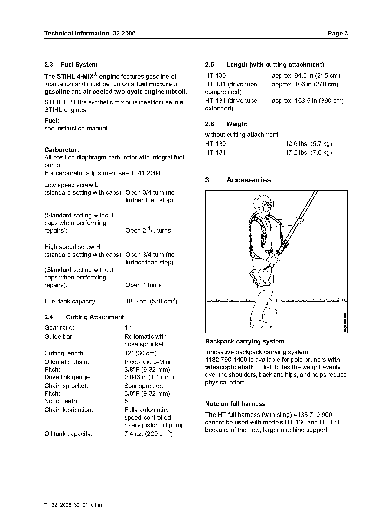
                               nose sprocket               Backpack carrying system
Cutting length:                12" (30 cm)                 Innovative backpack carrying system
Oilomatic chain:               Picco Micro-Mini            4182 790 4400 is available for pole pruners with
Pitch:                         3/8"P (9.32 mm)             telescopic shaft. It distributes the weight evenly
Drive link gauge:              0.043 in (1.1 mm)           over the shoulders, back and hips, and helps reduce
                                                           physical effort.
Chain sprocket:                Spur sprocket
Pitch:                         3/8"P (9.32 mm)
No. of teeth:                  6                           Note on full harness
Chain lubrication:             Fully automatic,
                               speed-controlled            The HT full harness (with sling) 4138 710 9001
                               rotary piston oil pump      cannot be used with models HT 130 and HT 131
                                                           because of the new, larger machine support.
Oil tank capacity:             7.4 oz. (220 cm3)

TI_32_2006_30_01_01.fm
Page 4 of 12
Text of page 4 — search, copy, screen readers
Page 4                                                                       Technical Information 32.2006

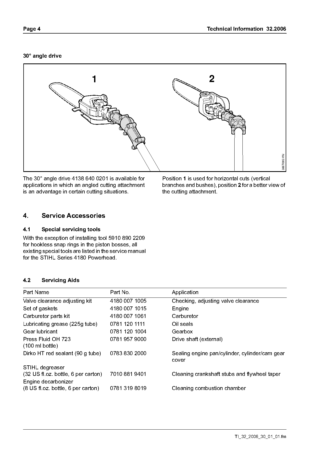
30° angle drive

                              1                                               2

                                                                                                             386TI003 KN
The 30° angle drive 4138 640 0201 is available for        Position 1 is used for horizontal cuts (vertical
applications in which an angled cutting attachment        branches and bushes), position 2 for a better view of
is an advantage in certain cutting situations.            the cutting attachment.

4.       Service Accessories

4.1      Special servicing tools
With the exception of installing tool 5910 890 2209
for hookless snap rings in the piston bosses, all
existing special tools are listed in the service manual
for the STIHL Series 4180 Powerhead.

4.2      Servicing Aids

Part Name                             Part No.                Application
Valve clearance adjusting kit         4180 007 1005           Checking, adjusting valve clearance
Set of gaskets                        4180 007 1015           Engine
Carburetor parts kit                  4180 007 1061           Carburetor
Lubricating grease (225g tube)        0781 120 1111           Oil seals
Gear lubricant                        0781 120 1004           Gearbox
Press Fluid OH 723                    0781 957 9000           Drive shaft (external)
(100 ml bottle)
Dirko HT red sealant (90 g tube)      0783 830 2000           Sealing engine pan/cylinder, cylinder/cam gear
                                                              cover
STIHL degreaser
(32 US fl.oz. bottle, 6 per carton)   7010 881 9401           Cleaning crankshaft stubs and flywheel taper
Engine decarbonizer
(8 US fl.oz. bottle, 6 per carton)     0781 319 8019          Cleaning combustion chamber

                                                                                         TI_32_2006_30_01_01.fm
Page 5 of 12
Text of page 5 — search, copy, screen readers
Technical Information 32.2006                                                                                     Page 5

5.       Assembly Instructions
                                                                                         1      2
Pole pruners shipped from the factory are not                                            3      4
completely assembled.
The gearbox has to be mounted on the HT 130. The
powerhead and gearbox have to be mounted on the
HT 131.
Warning! The engine may be started only with the
drive tube properly mounted – there is otherwise a
risk of engine damage and personal injury.

                                                                                                                         246TI001 KN
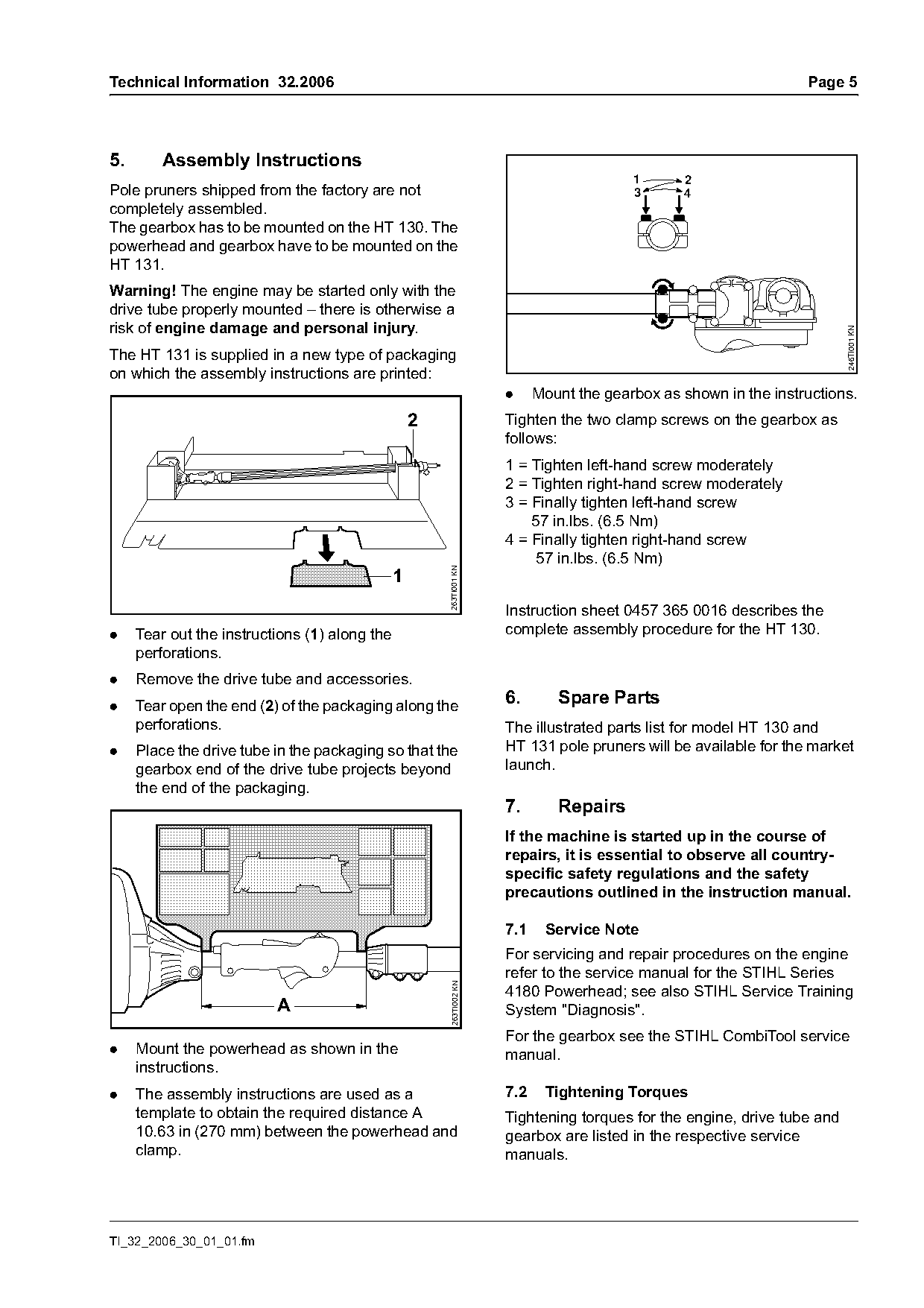
The HT 131 is supplied in a new type of packaging
on which the assembly instructions are printed:
                                                                     .     Mount the gearbox as shown in the instructions.
                                                   2                 Tighten the two clamp screws on the gearbox as
                                                                     follows:
                                                                     1 = Tighten left-hand screw moderately
                                                                     2 = Tighten right-hand screw moderately
                                                                     3 = Finally tighten left-hand screw
                                                                         57 in.lbs. (6.5 Nm)
                                                                     4 = Finally tighten right-hand screw
                                                                         57 in.lbs. (6.5 Nm)
                                                       263TI001 KN

                                               1
                                                                     Instruction sheet 0457 365 0016 describes the
.    Tear out the instructions (1) along the                         complete assembly procedure for the HT 130.
     perforations.
.    Remove the drive tube and accessories.
.    Tear open the end (2) of the packaging along the                6.       Spare Parts
     perforations.                                                   The illustrated parts list for model HT 130 and
.    Place the drive tube in the packaging so that the               HT 131 pole pruners will be available for the market
     gearbox end of the drive tube projects beyond                   launch.
     the end of the packaging.
                                                                     7.       Repairs
                                                                     If the machine is started up in the course of
                                                                     repairs, it is essential to observe all country-
                                                                     specific safety regulations and the safety
                                                                     precautions outlined in the instruction manual.

                                                                     7.1    Service Note
                                                                     For servicing and repair procedures on the engine
                                                                     refer to the service manual for the STIHL Series
                                                       263TI002 KN

                                                                     4180 Powerhead; see also STIHL Service Training
                          A                                          System "Diagnosis".
                                                                     For the gearbox see the STIHL CombiTool service
.    Mount the powerhead as shown in the                             manual.
     instructions.
.    The assembly instructions are used as a                         7.2    Tightening Torques
     template to obtain the required distance A                      Tightening torques for the engine, drive tube and
     10.63 in (270 mm) between the powerhead and                     gearbox are listed in the respective service
     clamp.                                                          manuals.

TI_32_2006_30_01_01.fm
Page 6 of 12
Text of page 6 — search, copy, screen readers
Page 6                                                                                Technical Information 32.2006

7.3      Checking valve clearance                            7.4        Replacing the gearbox
Valve clearances can be checked and adjusted if              Use only the new gearbox 4182 640 0104 as a
necessary after "break-in" (139 hours of operation).         replacement. The gearbox is marked “0104”.
Check and adjust valve clearances only when the              Use gear lubricant 0781 120 1004 for lubrication of
engine is cold. Use the valve clearance adjusting kit        the gearbox.
4180 007 1005, consisting of feeler gauge, sealing
ring and gasket.                                             .     Quantity of gear lubricant: 0.4 oz. (12 g)

7.5      HT 131 drive tube: Disassembling and
         assembling
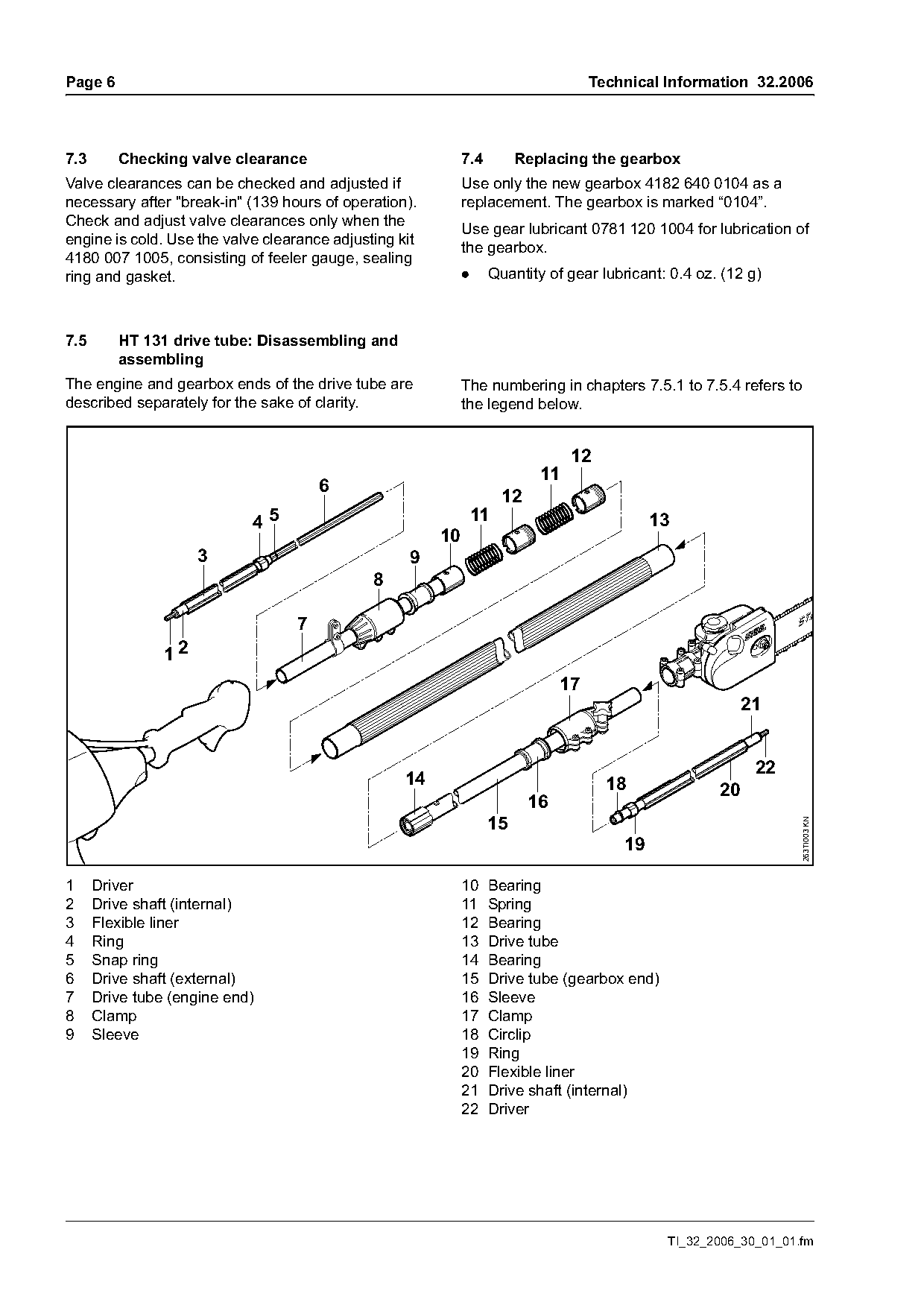
The engine and gearbox ends of the drive tube are            The numbering in chapters 7.5.1 to 7.5.4 refers to
described separately for the sake of clarity.                the legend below.

                                                                                  12
                                                                            11
                                      6
                                                                      12
                            45                                   11                            13
                                                        10
                     3                             9
                                              8

                                  7
                12
                                                                                 17
                                                                                                            21

                                                                                                             22
                                                   14                                   18             20
                                                                           16
                                                                   15
                                                                                                                    263TI003 KN


1     Driver                                                 10 Bearing
2     Drive shaft (internal)                                 11 Spring
3     Flexible liner                                         12 Bearing
4     Ring                                                   13 Drive tube
5     Snap ring                                              14 Bearing
6     Drive shaft (external)                                 15 Drive tube (gearbox end)
7     Drive tube (engine end)                                16 Sleeve
8     Clamp                                                  17 Clamp
9     Sleeve                                                 18 Circlip
                                                             19 Ring
                                                             20 Flexible liner
                                                             21 Drive shaft (internal)
                                                             22 Driver

                                                                                                TI_32_2006_30_01_01.fm
Page 7 of 12
Text of page 7 — search, copy, screen readers
Technical Information 32.2006                                                                                       Page 7

7.5.1   Disassembling (engine end)                                    -   Check condition of driver, drive shafts, snap
                                                                          ring, ring and liner, and replace if necessary.
                                                                          If the driver is damaged:
                                                                          Replace the drive shaft (with preassembled
                                                                          driver, part number 4182 710 3201 or use a
                                                                          press to remove the driver from the drive shaft
                                                                          (internal). Install new driver.
                                                                      -   Make sure the snap ring is properly seated in
                                                                          the groove.
                                                                      -   If necessary, remove rivet and pull the bearing

                                                        263TI004 KN
                                                                          off the drive tube. Only use original STIHL rivet
                                                                          9438 003 3171 for reassembly.

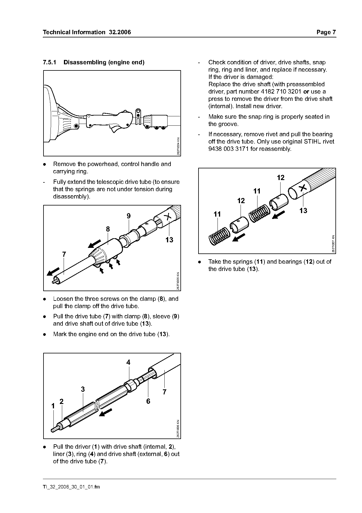
.   Remove the powerhead, control handle and
    carrying ring.
                                                                                                    12
-   Fully extend the telescopic drive tube (to ensure
    that the springs are not under tension during                                          11
    disassembly).
                                                                                     12
                                                                                                             13
                                  9                                        11


                                                                                                                           263TI007 KN
                                                   13
        7
                                                                      .   Take the springs (11) and bearings (12) out of
                                                                          the drive tube (13).
                                                        263TI005 KN

.   Loosen the three screws on the clamp (8), and
    pull the clamp off the drive tube.
.   Pull the drive tube (7) with clamp (8), sleeve (9)
    and drive shaft out of drive tube (13).
.   Mark the engine end on the drive tube (13).


               3                                 7
        2                                  6
    1
                                                        263TI006 KN

.   Pull the driver (1) with drive shaft (internal, 2),
    liner (3), ring (4) and drive shaft (external, 6) out
    of the drive tube (7).

TI_32_2006_30_01_01.fm
Page 8 of 12
Text of page 8 — search, copy, screen readers
Page 8                                                                                      Technical Information 32.2006

7.5.2     Disassembling (gearbox end)                                   -   Pull the liner and ring off the drive shaft
                                                                            (internal).
                                                                        -   Check condition of driver, drive shaft, circlip, ring
                      1
                                                                            and liner, and replace if necessary.
                                                                            If the driver is damaged:
             2
                                                                            Replace the drive shaft (with preassembled
                                                                            driver, part number 4182 710 3204 or use a
                                                                            press to remove the driver from the drive shaft
                      1                                                     (internal). Install new driver.
                                                                        -   If necessary, remove rivet and pull the bearing

                                                          386TI009 KN
                                                                            off the drive tube. Only use original STIHL rivet
                                                                            9438 003 3171 for reassembly.

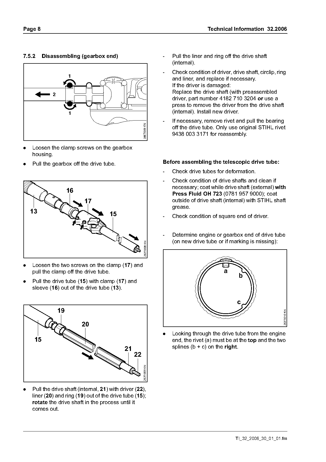
.   Loosen the clamp screws on the gearbox
    housing.
.   Pull the gearbox off the drive tube.                                Before assembling the telescopic drive tube:
                                                                        -   Check drive tubes for deformation.
                                                                        -   Check condition of drive shafts and clean if
                                                                            necessary; coat while drive shaft (external) with
                      16                                                    Press Fluid OH 723 (0781 957 9000); coat
                            17                                              outside of drive shaft (internal) with STIHL shaft
                                                                            grease.
    13                                 15                               -   Check condition of square end of driver.

                                                                        -   Determine engine or gearbox end of drive tube
                                                                            (on new drive tube or if marking is missing):
                                                         263TI008 KN

.   Loosen the two screws on the clamp (17) and
    pull the clamp off the drive tube.                                                              a
                                                                                                           b
.   Pull the drive tube (15) with clamp (17) and
    sleeve (16) out of the drive tube (13).

                                                                                                          c
                 19
                                                                                                                               263TI010 KN

                           20
                                                                        .   Looking through the drive tube from the engine
     15                                                                     end, the rivet (a) must be at the top and the two
                                               21                           splines (b + c) on the right.
                                                    22
                                                         263TI009 KN

.   Pull the drive shaft (internal, 21) with driver (22),
    liner (20) and ring (19) out of the drive tube (15);
    rotate the drive shaft in the process until it
    comes out.

                                                                                                         TI_32_2006_30_01_01.fm
Page 9 of 12
Text of page 9 — search, copy, screen readers
Technical Information 32.2006                                                                                      Page 9

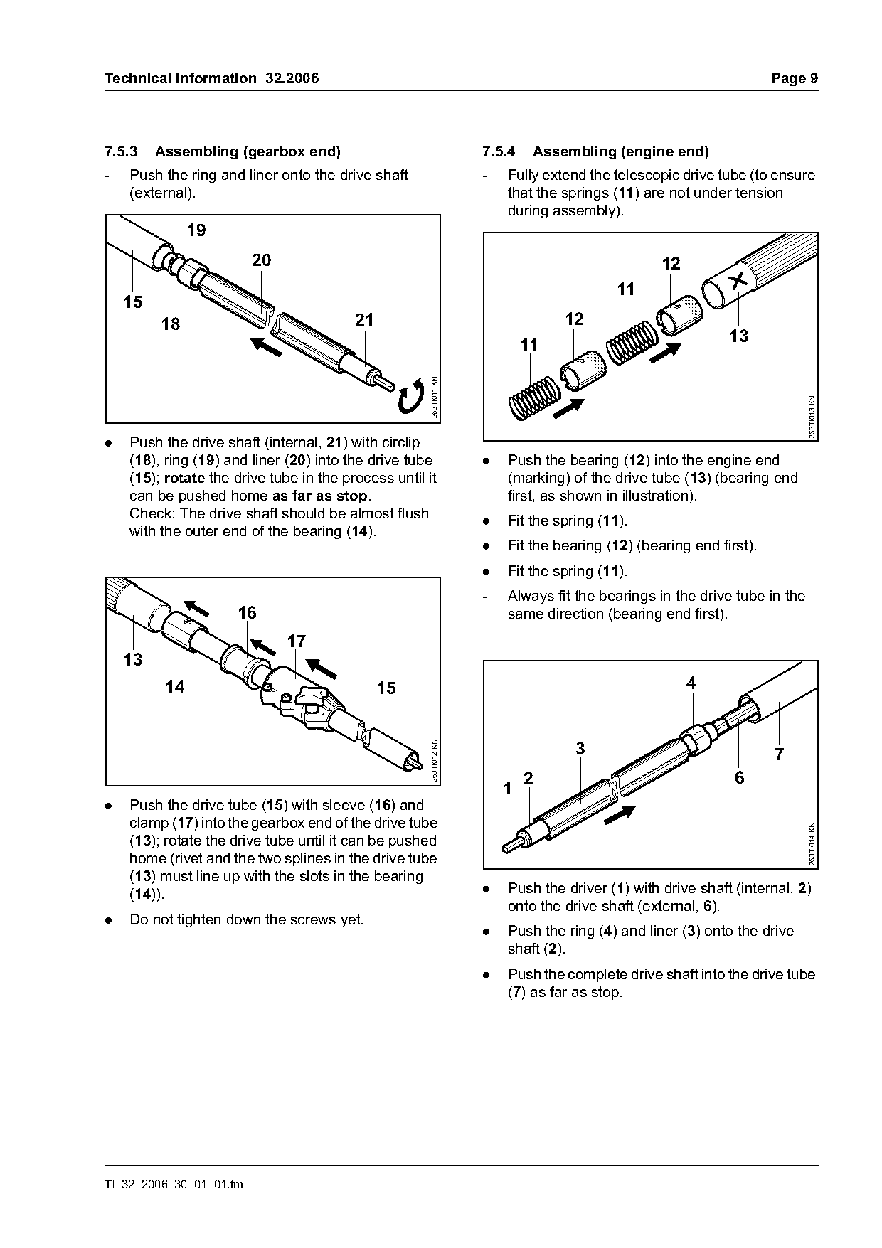
7.5.3    Assembling (gearbox end)                                  7.5.4    Assembling (engine end)
-   Push the ring and liner onto the drive shaft                   -   Fully extend the telescopic drive tube (to ensure
    (external).                                                        that the springs (11) are not under tension
                                                                       during assembly).
               19
                         20                                                                     12
                                                                                         11
    15
         18                              21                                     12
                                                                                                           13
                                                                           11

                                                     263TI011 KN

                                                                                                                          263TI013 KN
.   Push the drive shaft (internal, 21) with circlip
    (18), ring (19) and liner (20) into the drive tube             .   Push the bearing (12) into the engine end
    (15); rotate the drive tube in the process until it                (marking) of the drive tube (13) (bearing end
    can be pushed home as far as stop.                                 first, as shown in illustration).
    Check: The drive shaft should be almost flush                  .   Fit the spring (11).
    with the outer end of the bearing (14).
                                                                   .   Fit the bearing (12) (bearing end first).
                                                                   .   Fit the spring (11).
                                                                   -   Always fit the bearings in the drive tube in the
                     16                                                same direction (bearing end first).
                              17
    13
          14                                  15                                                     4

                                                                                  3
                                                     263TI012 KN

                                                                                                                   7
                                                                           2                                6
                                                                       1
.   Push the drive tube (15) with sleeve (16) and
    clamp (17) into the gearbox end of the drive tube
                                                                                                                          263TI014 KN

    (13); rotate the drive tube until it can be pushed
    home (rivet and the two splines in the drive tube
    (13) must line up with the slots in the bearing
    (14)).                                                         .   Push the driver (1) with drive shaft (internal, 2)
                                                                       onto the drive shaft (external, 6).
.   Do not tighten down the screws yet.
                                                                   .   Push the ring (4) and liner (3) onto the drive
                                                                       shaft (2).
                                                                   .   Push the complete drive shaft into the drive tube
                                                                       (7) as far as stop.

TI_32_2006_30_01_01.fm
Page 10 of 12
Text of page 10 — search, copy, screen readers
Page 10                                                                                   Technical Information 32.2006

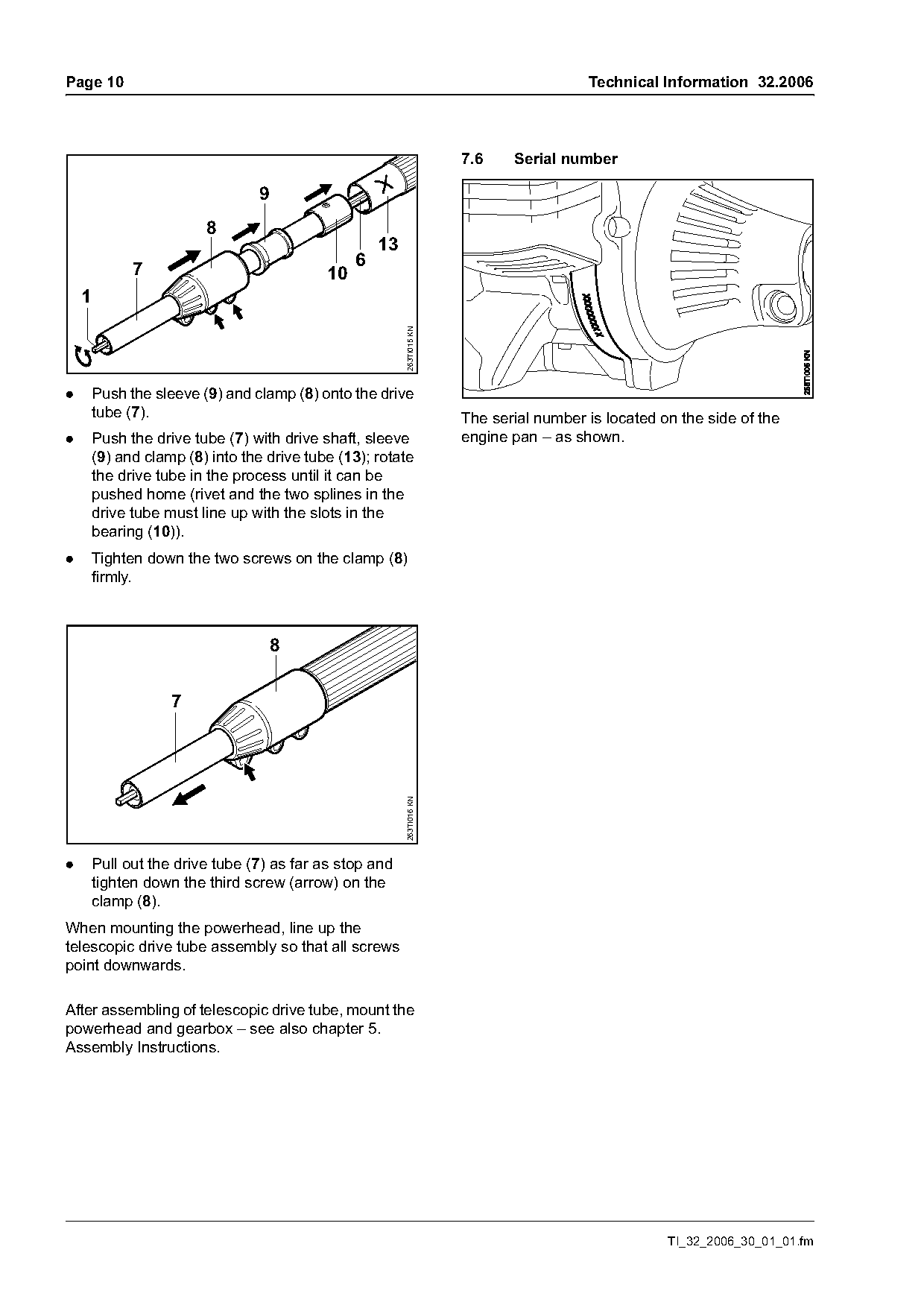
                                                                        7.6    Serial number

                                  9
                         8
                                                     13
              7                                  6
                                            10
    1

                                                          263TI015 KN
.       Push the sleeve (9) and clamp (8) onto the drive
        tube (7).                                                       The serial number is located on the side of the
.       Push the drive tube (7) with drive shaft, sleeve                engine pan – as shown.
        (9) and clamp (8) into the drive tube (13); rotate
        the drive tube in the process until it can be
        pushed home (rivet and the two splines in the
        drive tube must line up with the slots in the
        bearing (10)).
.       Tighten down the two screws on the clamp (8)
        firmly.


                    7
                                                          263TI016 KN

.       Pull out the drive tube (7) as far as stop and
        tighten down the third screw (arrow) on the
        clamp (8).
When mounting the powerhead, line up the
telescopic drive tube assembly so that all screws
point downwards.

After assembling of telescopic drive tube, mount the
powerhead and gearbox – see also chapter 5.
Assembly Instructions.

                                                                                                      TI_32_2006_30_01_01.fm
Page 11 of 12
Text of page 11 — search, copy, screen readers
Technical Information 32.2006                                                                   Page 11

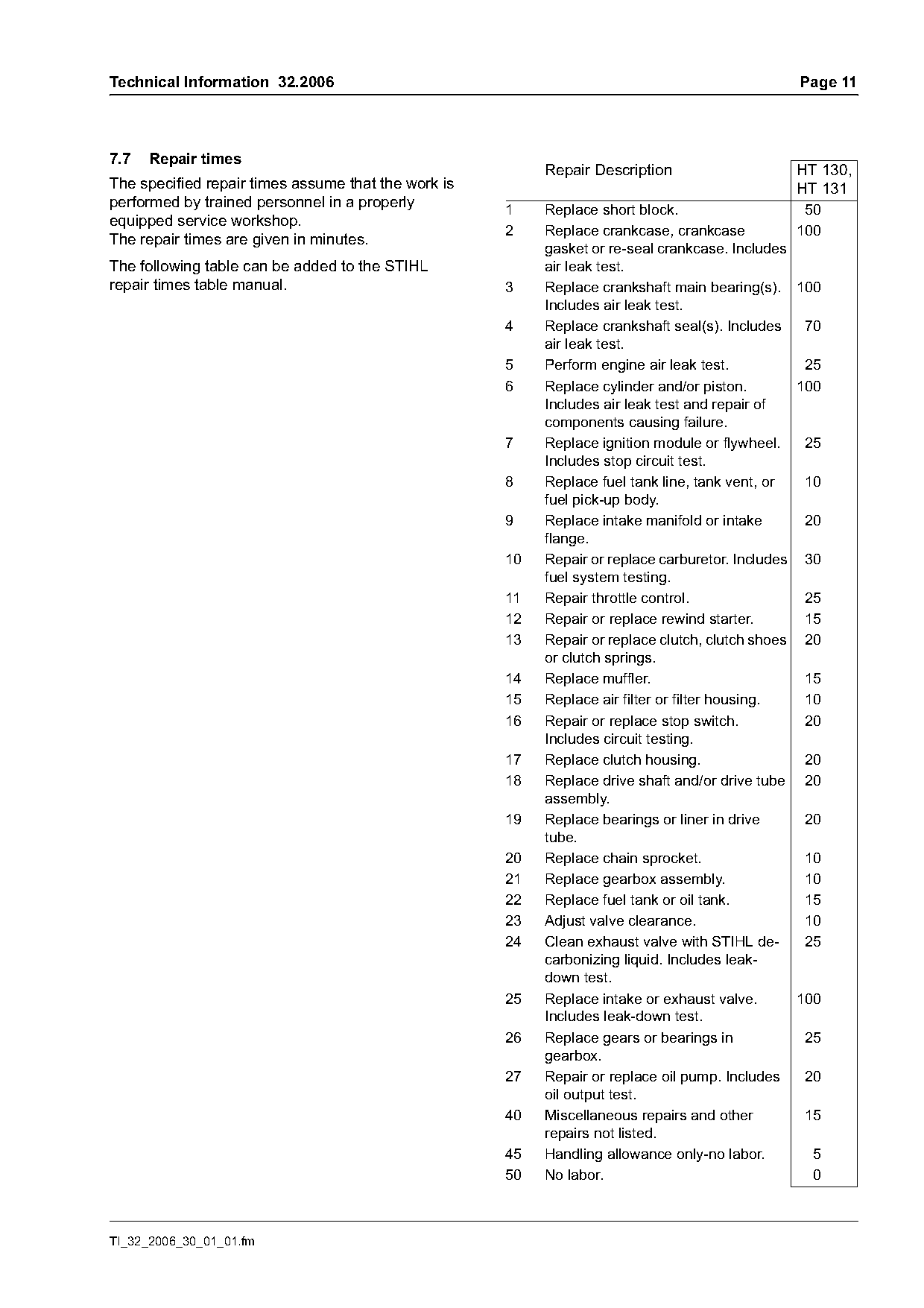
7.7   Repair times
                                                          Repair Description                    HT 130,
The specified repair times assume that the work is                                              HT 131
performed by trained personnel in a properly         1    Replace short block.                   50
equipped service workshop.
                                                     2    Replace crankcase, crankcase          100
The repair times are given in minutes.
                                                          gasket or re-seal crankcase. Includes
The following table can be added to the STIHL             air leak test.
repair times table manual.                           3    Replace crankshaft main bearing(s). 100
                                                          Includes air leak test.
                                                     4    Replace crankshaft seal(s). Includes    70
                                                          air leak test.
                                                     5    Perform engine air leak test.           25
                                                     6    Replace cylinder and/or piston.        100
                                                          Includes air leak test and repair of
                                                          components causing failure.
                                                     7    Replace ignition module or flywheel.    25
                                                          Includes stop circuit test.
                                                     8    Replace fuel tank line, tank vent, or   10
                                                          fuel pick-up body.
                                                     9    Replace intake manifold or intake       20
                                                          flange.
                                                     10   Repair or replace carburetor. Includes 30
                                                          fuel system testing.
                                                     11   Repair throttle control.                25
                                                     12   Repair or replace rewind starter.       15
                                                     13   Repair or replace clutch, clutch shoes 20
                                                          or clutch springs.
                                                     14   Replace muffler.                        15
                                                     15   Replace air filter or filter housing.   10
                                                     16   Repair or replace stop switch.          20
                                                          Includes circuit testing.
                                                     17   Replace clutch housing.                 20
                                                     18   Replace drive shaft and/or drive tube 20
                                                          assembly.
                                                     19   Replace bearings or liner in drive      20
                                                          tube.
                                                     20   Replace chain sprocket.                 10
                                                     21   Replace gearbox assembly.               10
                                                     22   Replace fuel tank or oil tank.          15
                                                     23   Adjust valve clearance.                 10
                                                     24   Clean exhaust valve with STIHL de-      25
                                                          carbonizing liquid. Includes leak-
                                                          down test.
                                                     25   Replace intake or exhaust valve.       100
                                                          Includes leak-down test.
                                                     26   Replace gears or bearings in            25
                                                          gearbox.
                                                     27   Repair or replace oil pump. Includes    20
                                                          oil output test.
                                                     40   Miscellaneous repairs and other         15
                                                          repairs not listed.
                                                     45   Handling allowance only-no labor.        5
                                                     50   No labor.                                0

TI_32_2006_30_01_01.fm
Page 12 of 12
Text of page 12 — search, copy, screen readers
Page 12                                             Technical Information 32.2006

© ANDREAS STIHL AG & Co. KG, 2006   Technical Documentation
                                    D1/MTK-ja

                                                              TI_32_2006_30_01_01.fm
Most of these PDFs embed fonts with a shifted character map, so the text above was recovered rather than copied — read it as a faithful but imperfect transcription, and treat the page image above each block as the authority where the two disagree — the figures exist only there, because they are vector drawings that text extraction cannot keep.