Technical Information · issue 34 of 2006
Filler cap O-ring; Tank vent system; New special accessory:; antistatic wire kit
IssueTI 34/2006
Part changes (2)
| Was | Becomes | What the bulletin says |
|---|---|---|
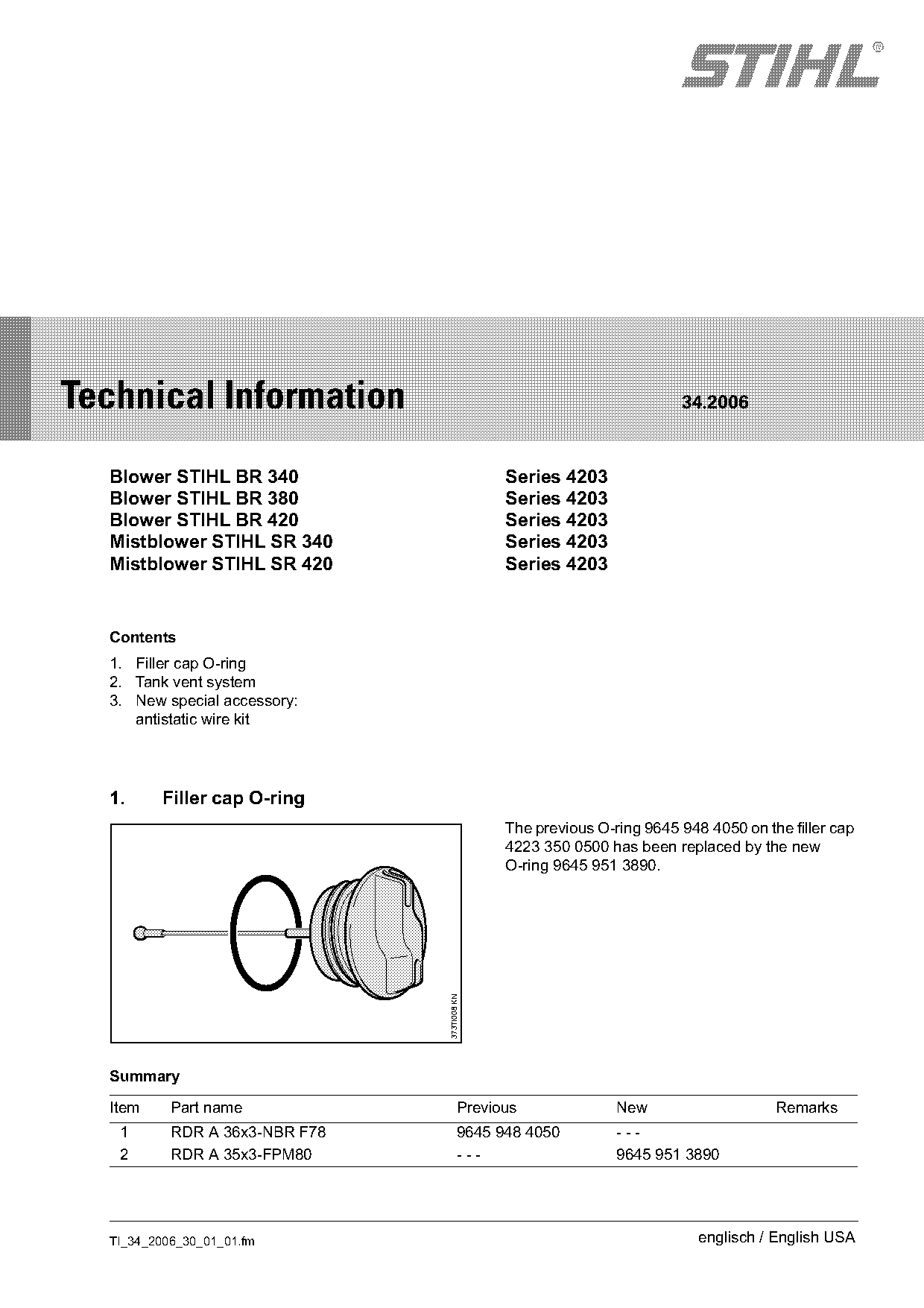
| 9645 948 4050 | 9645 951 3890 | Filler cap O-ring The previous O-ring 9645 948 4050 on the filler cap 4223 350 0500 has been replaced by the new O-ring 9645 951 3890. |
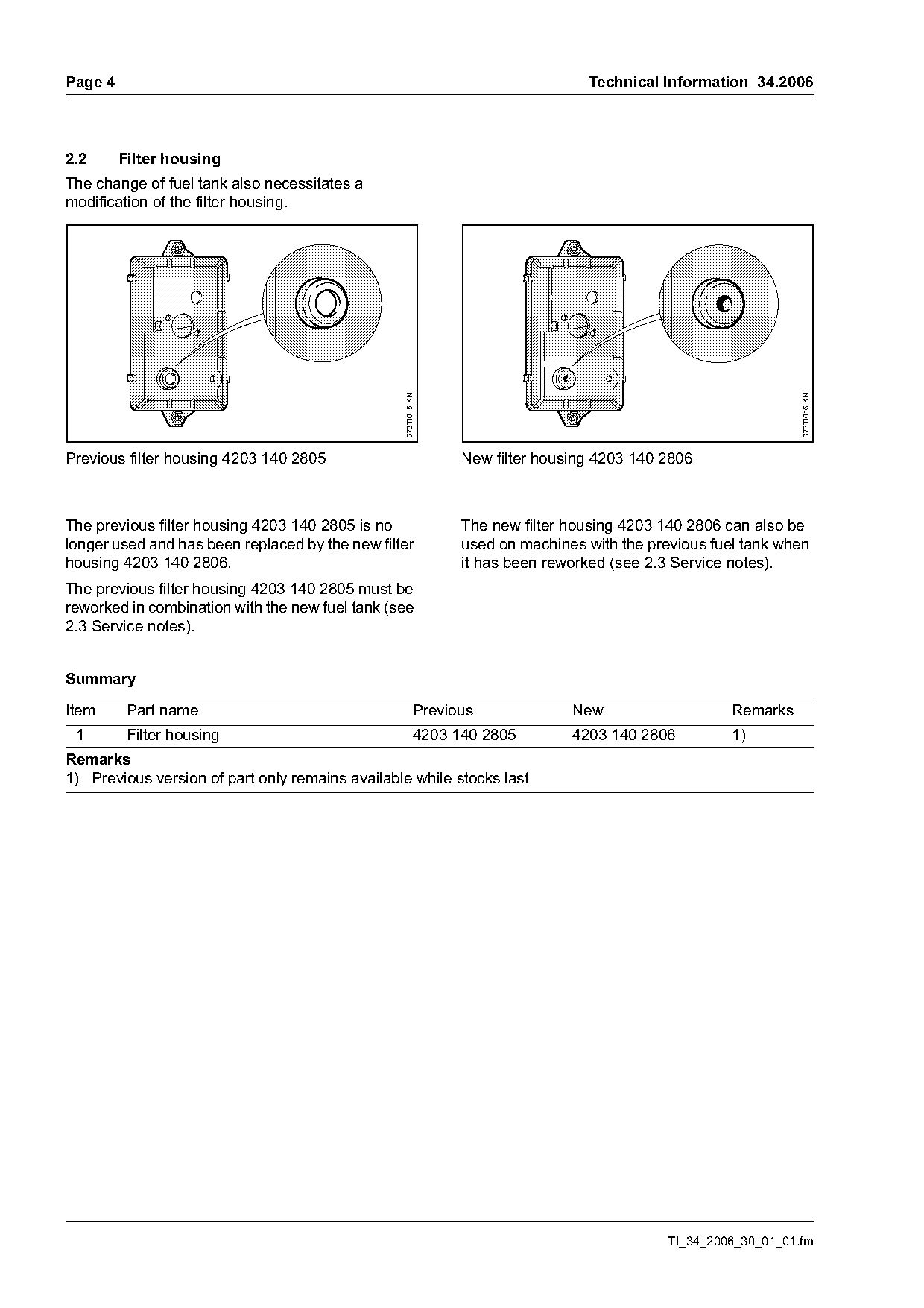
| 4203 140 2805 | 4203 140 2806 | The previous filter housing 4203 140 2805 is no The new filter housing 4203 140 2806 can also be longer used and has been replaced by the new filter used on machines with the previous fuel tank when housing 4203 140 2806. |
Full text
Page 1 of 8
Text of page 1 — search, copy, screen readers
STIH)

Technical Information                                                   34.2006

  Blower STIHL BR 340                          Series 4203
  Blower STIHL BR 380                          Series 4203
  Blower STIHL BR 420                          Series 4203
  Mistblower STIHL SR 340                      Series 4203
  Mistblower STIHL SR 420                      Series 4203

  Contents
  1. Filler cap O-ring
  2. Tank vent system
  3. New special accessory:
     antistatic wire kit

  1.     Filler cap O-ring
                                               The previous O-ring 9645 948 4050 on the filler cap
                                               4223 350 0500 has been replaced by the new
                                               O-ring 9645 951 3890.
                                373TI008 KN

  Summary

  Item     Part name                     Previous              New                    Remarks
   1       RDR A 36x3-NBR F78            9645 948 4050         ---
   2       RDR A 35x3-FPM80              ---                   9645 951 3890

  TI_34_2006_30_01_01.fm                                                   englisch / English USA
Page 2 of 8
Text of page 2 — search, copy, screen readers
Page 2                                                                                 Technical Information 34.2006

2.       Tank vent system

2.1      Fuel tank

                                                                                                                        373TI010 KN
                                                      373TI009 KN

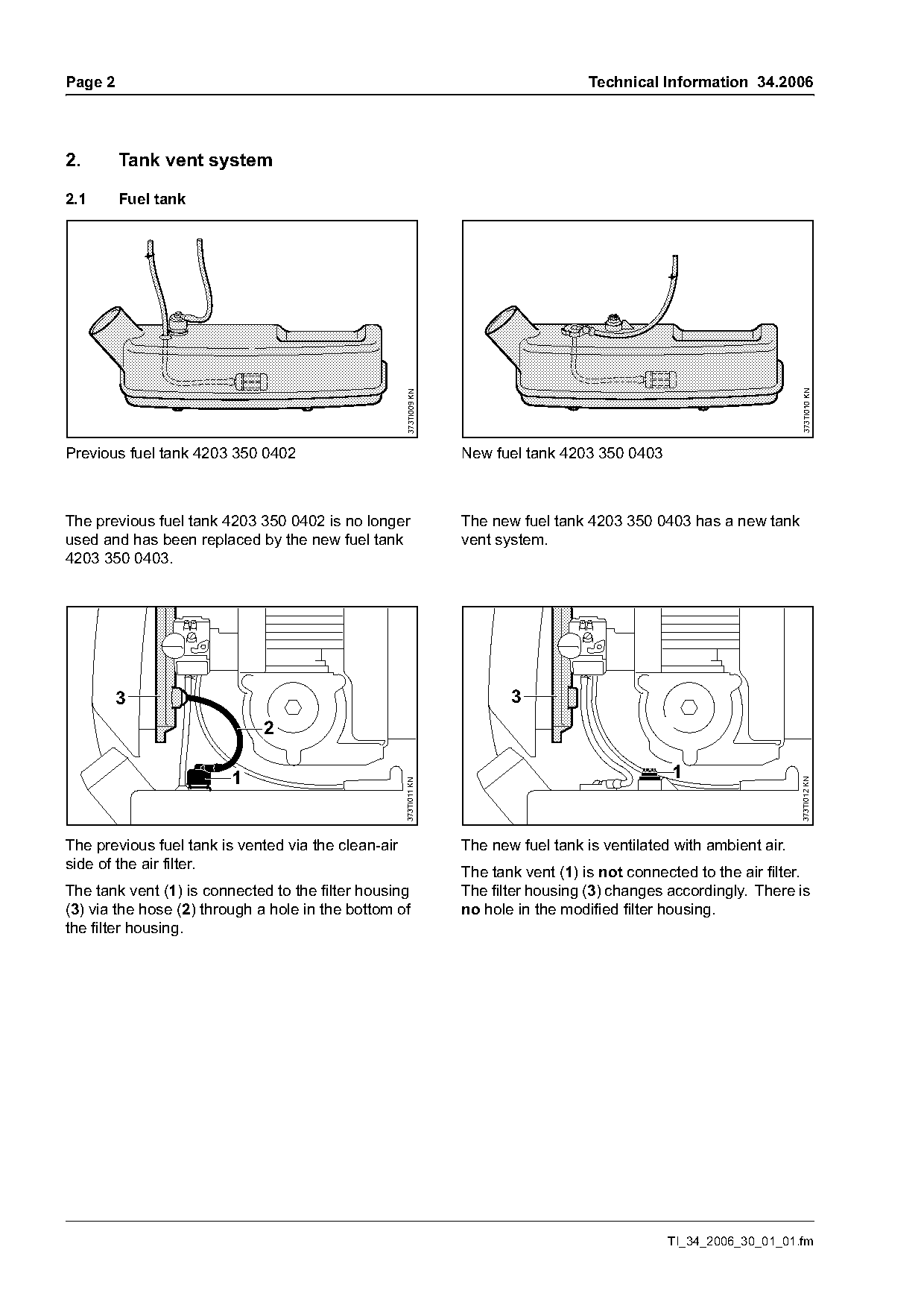
Previous fuel tank 4203 350 0402                                    New fuel tank 4203 350 0403

The previous fuel tank 4203 350 0402 is no longer                   The new fuel tank 4203 350 0403 has a new tank
used and has been replaced by the new fuel tank                     vent system.
4203 350 0403.

         3                                                                 3
                             2

                         1                                                                          1
                                                                                                                        373TI012 KN
                                                     373TI011 KN

The previous fuel tank is vented via the clean-air                  The new fuel tank is ventilated with ambient air.
side of the air filter.                                             The tank vent (1) is not connected to the air filter.
The tank vent (1) is connected to the filter housing                The filter housing (3) changes accordingly. There is
(3) via the hose (2) through a hole in the bottom of                no hole in the modified filter housing.
the filter housing.

                                                                                                   TI_34_2006_30_01_01.fm
Page 3 of 8
Text of page 3 — search, copy, screen readers
Technical Information 34.2006                                                                                Page 3

                                                                     8                                         10
       7                                     5                                                                 7

       4
                                             6                       9                          12             11
       3

                                                   373TI013 KN

                                                                                                                    373TI014 KN
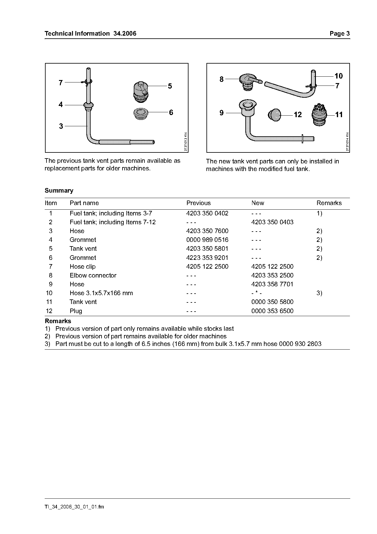
The previous tank vent parts remain available as                 The new tank vent parts can only be installed in
replacement parts for older machines.                            machines with the modified fuel tank.

Summary

Item       Part name                                      Previous               New                    Remarks
 1         Fuel tank; including Items 3-7                 4203 350 0402          ---                    1)
 2         Fuel tank; including Items 7-12                ---                    4203 350 0403
 3         Hose                                           4203 350 7600          ---                    2)
 4         Grommet                                        0000 989 0516          ---                    2)
 5         Tank vent                                      4203 350 5801          ---                    2)
 6         Grommet                                        4223 353 9201          ---                    2)
 7         Hose clip                                      4205 122 2500          4205 122 2500
 8         Elbow connector                                ---                    4203 353 2500
 9         Hose                                           ---                    4203 358 7701
10         Hose 3.1x5.7x166 mm                            ---                    -*-                    3)
11         Tank vent                                      ---                    0000 350 5800
12         Plug                                           ---                    0000 353 6500
Remarks
1) Previous version of part only remains available while stocks last
2) Previous version of part remains available for older machines
3) Part must be cut to a length of 6.5 inches (166 mm) from bulk 3.1x5.7 mm hose 0000 930 2803

TI_34_2006_30_01_01.fm
Page 4 of 8
Text of page 4 — search, copy, screen readers
Page 4                                                                           Technical Information 34.2006

2.2      Filter housing
The change of fuel tank also necessitates a
modification of the filter housing.

                                                 373TI015 KN

                                                                                                                 373TI016 KN
Previous filter housing 4203 140 2805                           New filter housing 4203 140 2806

The previous filter housing 4203 140 2805 is no                 The new filter housing 4203 140 2806 can also be
longer used and has been replaced by the new filter             used on machines with the previous fuel tank when
housing 4203 140 2806.                                          it has been reworked (see 2.3 Service notes).
The previous filter housing 4203 140 2805 must be
reworked in combination with the new fuel tank (see
2.3 Service notes).

Summary

Item      Part name                                       Previous             New                    Remarks
 1        Filter housing                                  4203 140 2805        4203 140 2806          1)
Remarks
1) Previous version of part only remains available while stocks last

                                                                                             TI_34_2006_30_01_01.fm
Page 5 of 8
Text of page 5 — search, copy, screen readers
Technical Information 34.2006                                                                                Page 5

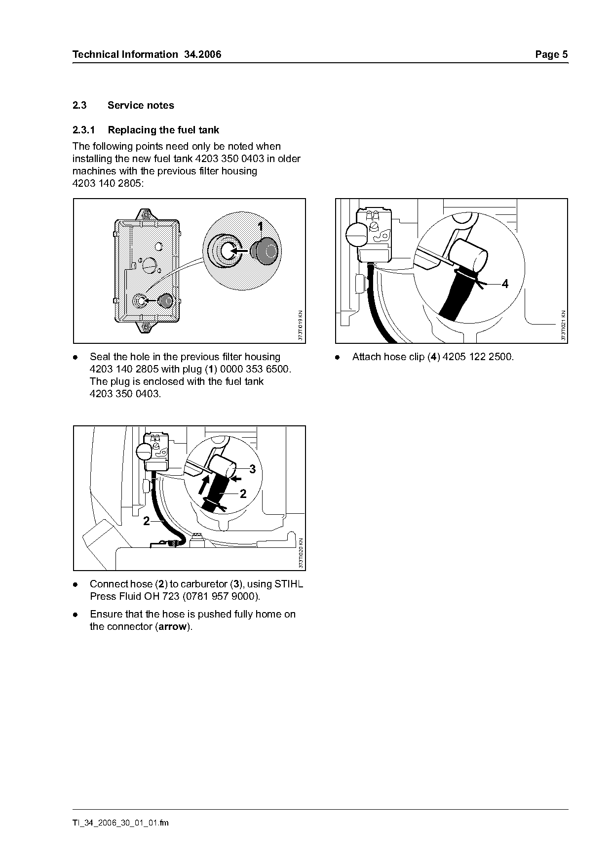
2.3      Service notes

2.3.1    Replacing the fuel tank
The following points need only be noted when
installing the new fuel tank 4203 350 0403 in older
machines with the previous filter housing
4203 140 2805:

                                                                                                       4
                                                     373TI019 KN

                                                                                                                 373TI021 KN
.     Seal the hole in the previous filter housing                 .   Attach hose clip (4) 4205 122 2500.
      4203 140 2805 with plug (1) 0000 353 6500.
      The plug is enclosed with the fuel tank
      4203 350 0403.


                 2
                                                     373TI020 KN

.     Connect hose (2) to carburetor (3), using STIHL
      Press Fluid OH 723 (0781 957 9000).
.     Ensure that the hose is pushed fully home on
      the connector (arrow).

TI_34_2006_30_01_01.fm
Page 6 of 8
Text of page 6 — search, copy, screen readers
Page 6                                                             Technical Information 34.2006

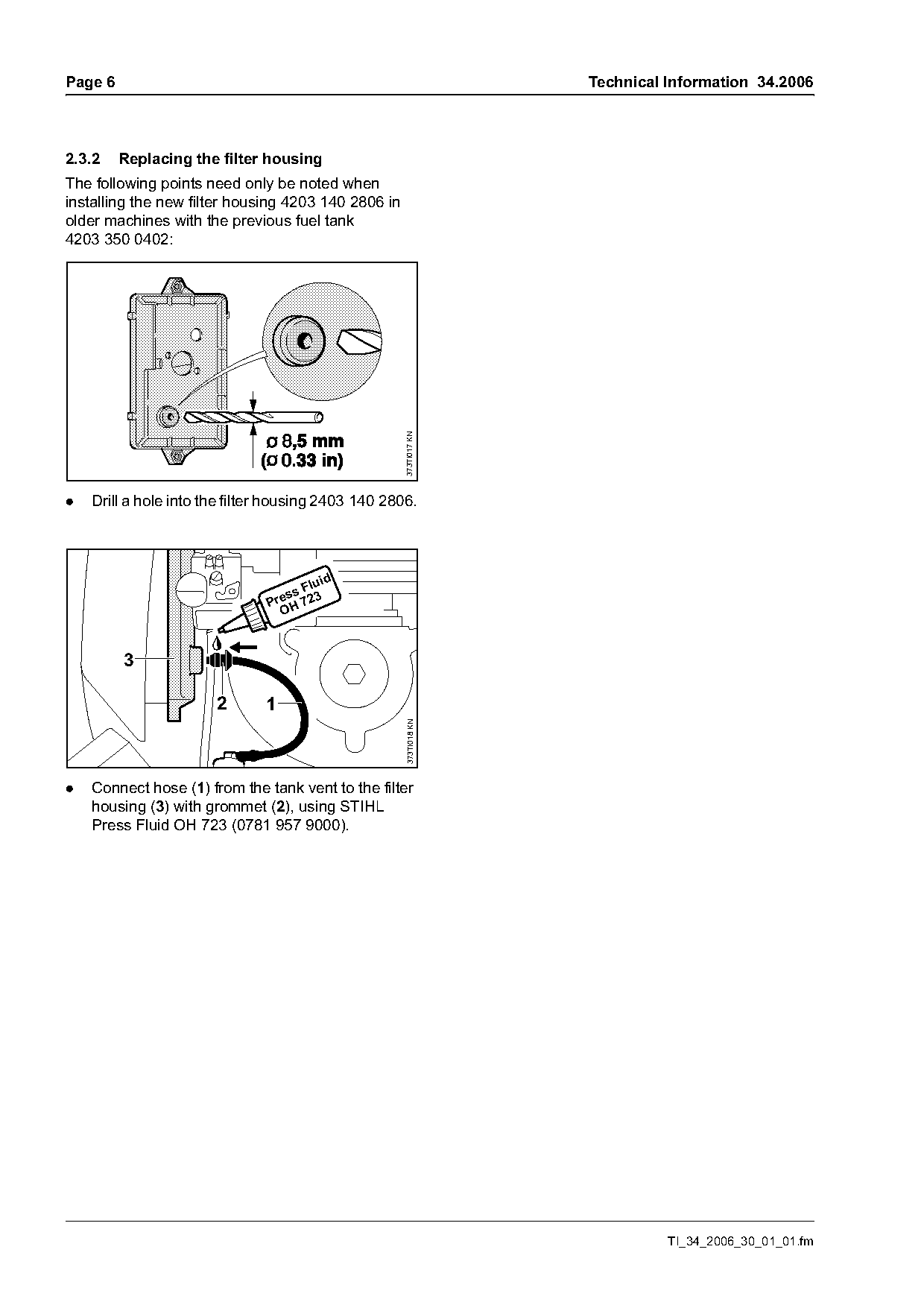
2.3.2    Replacing the filter housing
The following points need only be noted when
installing the new filter housing 4203 140 2806 in
older machines with the previous fuel tank
4203 350 0402:

                                                     373TI017 KN

.   Drill a hole into the filter housing 2403 140 2806.

                                         id
                                     Flu
                                  ss
                               Pre H 723


                       2       1
                                                     373TI018 KN

.   Connect hose (1) from the tank vent to the filter
    housing (3) with grommet (2), using STIHL
    Press Fluid OH 723 (0781 957 9000).

                                                                             TI_34_2006_30_01_01.fm
Page 7 of 8
Text of page 7 — search, copy, screen readers
Technical Information 34.2006                                                                                  Page 7

3.       New special accessory:
         antistatic wire kit
                                                               Fitting the antistatic wire kit


                                                373TI022 KN

                                                                                                                    373TI024 KN
                                                                                                          2
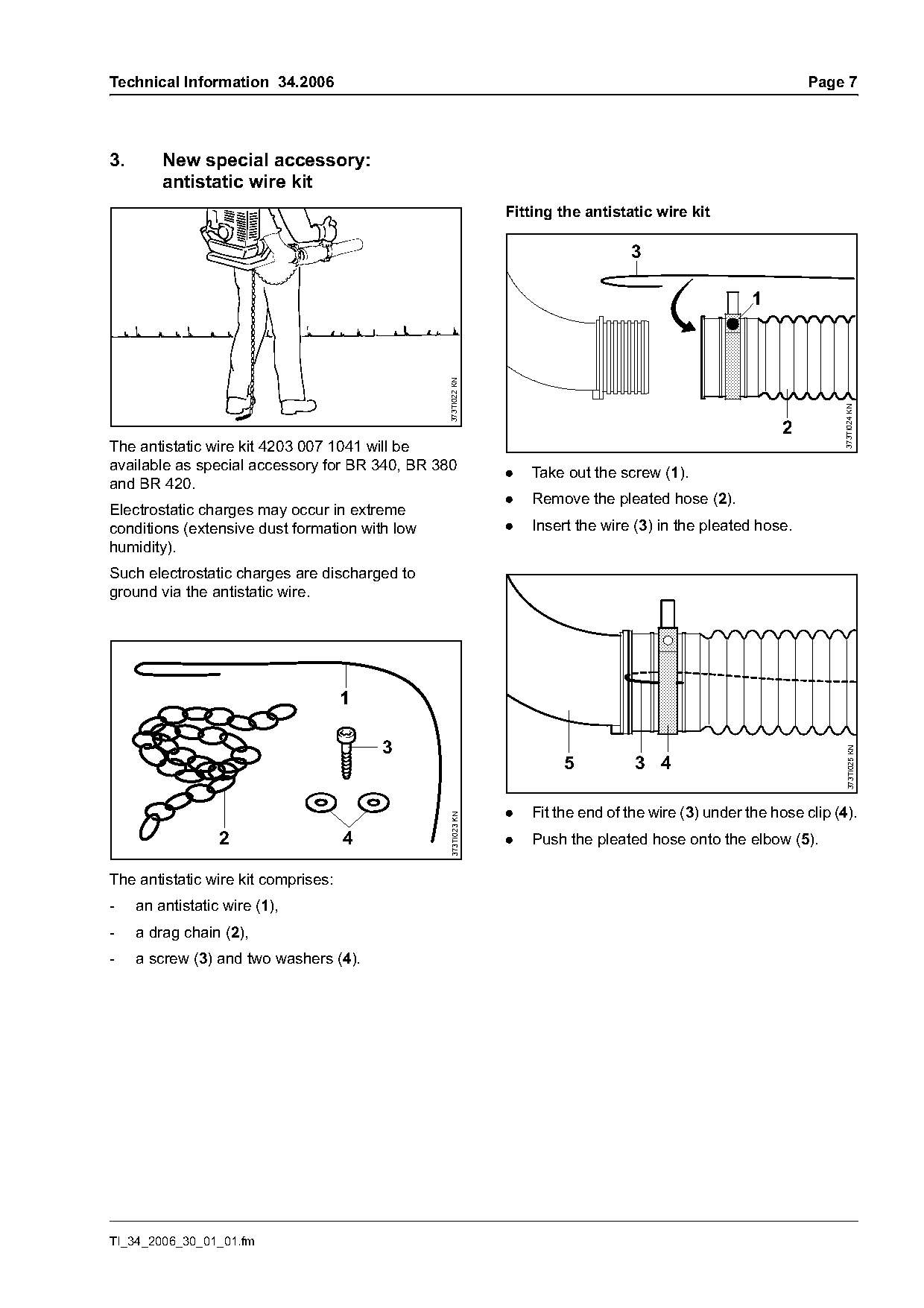
The antistatic wire kit 4203 007 1041 will be
available as special accessory for BR 340, BR 380              .   Take out the screw (1).
and BR 420.
                                                               .   Remove the pleated hose (2).
Electrostatic charges may occur in extreme
conditions (extensive dust formation with low                  .   Insert the wire (3) in the pleated hose.
humidity).
Such electrostatic charges are discharged to
ground via the antistatic wire.


                                                                                                                     373TI025 KN
                                                                        5          3 4

                                                               .   Fit the end of the wire (3) under the hose clip (4).
                                                 373TI023 KN

                  2                  4                         .   Push the pleated hose onto the elbow (5).

The antistatic wire kit comprises:
-    an antistatic wire (1),
-    a drag chain (2),
-    a screw (3) and two washers (4).

TI_34_2006_30_01_01.fm
Page 8 of 8
Text of page 8 — search, copy, screen readers
Page 8                                                                                  Technical Information 34.2006

                 7 1          8

                                                                                                 10
                                                                                                 9

                                                                                                                       373TI027 KN
                                                        373TI026 KN
                                                                                                        45 cm
                                                                                                       (18 in)

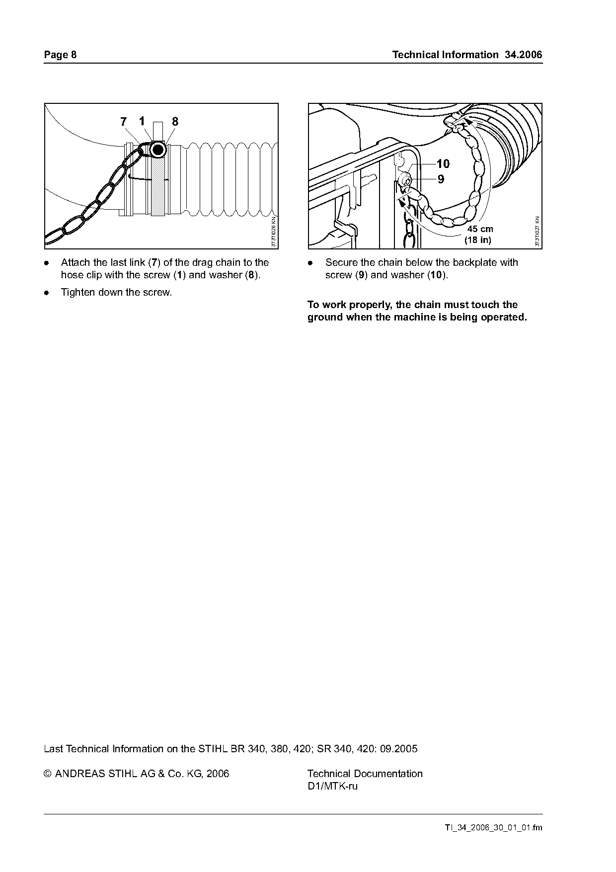
.   Attach the last link (7) of the drag chain to the                 .   Secure the chain below the backplate with
    hose clip with the screw (1) and washer (8).                          screw (9) and washer (10).
.   Tighten down the screw.
                                                                      To work properly, the chain must touch the
                                                                      ground when the machine is being operated.

Last Technical Information on the STIHL BR 340, 380, 420; SR 340, 420: 09.2005

© ANDREAS STIHL AG & Co. KG, 2006                                     Technical Documentation
                                                                      D1/MTK-ru

                                                                                                   TI_34_2006_30_01_01.fm
Most of these PDFs embed fonts with a shifted character map, so the text above was recovered rather than copied — read it as a faithful but imperfect transcription, and treat the page image above each block as the authority where the two disagree — the figures exist only there, because they are vector drawings that text extraction cannot keep.