Technical Information · issue 36 of 2006
Seat (adjustment); Housing (screwing moldings together), carrier; Scope of supply FW 20, Seat for TS 400; New water container; Summary
IssueTI 36/2006
Full text
Page 1 of 5
Text of page 1 — search, copy, screen readers
STIH)

Technical Information                                                                            36.2006

  STIHL FW 20 cut-off machine cart                                      – Series 4224

  Contents
  1.   Mount (adjustment)
  2.   Depth wheel control assembly, carrier
  3.   FW 20 combinations, TS 400 and TS 410/420 mounting kits
  4.   New water tank
  5.   Summary

  1.      Mount (adjustment)
  In future it will be possible to readjust the cut-off                 Alignment of the mounted cut-off machine and
  machine on the FW 20 cart.                                            wheel tracking is described below.

                                                                        Checking the direction of travel

                                                1
                                                                                                                         379TI009 KN


                                                                        .   Position the FW 20 cart with mounted machine
                                                          379TI008 KN

                                                                            as shown – on a hard flat surface (concrete or
                                                                            asphalt). Only the cutting wheel and the rear
                                                                            wheels should be in contact with the ground.
  To allow for adjustment, the upper hole in the mount
  has been changed to an oblong slot (see arrow). A
  notch (1) marks the center position allowing the
  lower hole (2) to act as a pivot point.

  TI_36_2006_30_01_01.fm                                                                            englisch / English USA
Page 2 of 5
Text of page 2 — search, copy, screen readers
Page 2                                                                                     Technical Information 36.2006


                                                         379TI010 KN

                                                                                                                            379TI012 KN
.   Align the cutting wheel and cart along a straight                  .   Loosen the two nuts (1) on the underside of the
    chalk line                                                             cart
                                                                       If the direction deviates to the left:
                                                                       .   Swivel the mount (2) to the left
                                                                       .   Tighten the two nuts
                                                                       If the direction deviates to the right:
                                                                       .   Swivel the mount (2) to the right
                                                                       .   Tighten the two nuts

                                                                       Note: The full range of movement in the upper slot
                                                                       is around 0.670" (17 mm). A fine adjustment is
                                                                       generally all that is necessary to correct the
                                                                       deviation.
                                                                       Re-check the direction of travel and repeat the
                                                                       adjustment procedure described above if necessary
                                                                       until the deviation is corrected.
                                                         379TI011 KN

.   Push the cart gently forward so it travels a few
    feet

If the direction of travel deviates to the left or right of
the marked line, the mount should be adjusted (with
the machine mounted) as described below:

                                                                                                        TI_36_2006_30_01_01.fm
Page 3 of 5
Text of page 3 — search, copy, screen readers
Technical Information 36.2006                                                                                         Page 3

2.       Depth wheel control assembly,
         carrier
                                                                          Service note
                                                                          The previous housings cannot be combined with the
                                                                          new housings. The previous housings will therefore
                                                                          continue to be available for older machines.
                                                   1


                 2
                                           1
                                                                                                                2
                                                                                    1
                                                                                                               2
             2                         1 1

                                                                                                                           379TI015 KN
                                                           379TI013 KN

                                                                          The lever (1) is now fastened to the handle using
The way the housings were assembled and                                   screws (2) 9022 341 1430 (IS-M6x50x24) instead of
fastened to the handle have been changed.                                 screws 9027 068 1430 (M6x50, DIN 603).
Previously, the two housings were assembled using
5 IS-D5x24 screws (1). The threaded castings (2) in
the top housing established the housing position on                       Carrier
the handle.

         5                                     4
                                                                                                                           379TI016 KN

                         3
                                                                          With the introduction of a new mount for the STIHL
                                       4                                  TS 400 on the FW 20 cart (see chapter 3), the
                                                                          carrier (throttle control locking button) now has a
     5                                                                    second hole in which the throttle cable can be
                     3
                                                                          hooked. The two holes are marked A (TS 700, 800)
                                                            379TI014 KN

                                                                          and B (TS 400, 410, 420).

With the new design, the lower housing is fastened
directly to the handle using 2 D5x26 screws (3). The
upper housing is then fastened to the lower housing
using 2 IS-P6x30 screws (5).

TI_36_2006_30_01_01.fm
Page 4 of 5
Text of page 4 — search, copy, screen readers
Page 4                                                                                   Technical Information 36.2006

3.       FW 20 combinations, TS 400 and                               Only the necessary mounting kit has to be
         TS 410/420 mounting kits                                     purchased in order to retrofit the FW 20 cart for use
                                                                      with another recommended model of STIHL cut-off
To widen the range of applications, as well as the                    machine.
mount offered for the TS 700 and 800 already
described, two new mounts are also available for
                                                                      4.      New water tank
the TS 400 and TS 410/420. These new mounts are
also adjustable (see chapter 1.)
In future, the FW 20 will be available as a basic cart
with no mount. The mounting kits for the
TS 700/800, TS 400 and TS 410/420 will be offered
separately for the FW 20 cart depending on the end
user application.

                                              FW 20
                                              TS 700,
                                              TS 800

                                                                                                                          379TI018 KN
                                              FW 20                   The new water tank was developed especially for
                                              TS 400                  the FW 20 cart. The new tank is bevelled towards
                                                                      the front for a clear view of the working area. The
                                                                      see-through material allows for easy viewing of the
                                                                      water level. The bracket supplied with the water tank
                                                                      mounting kit can be mounted on any FW 20 cart with
                                                                      the use of two screws.
                                                                      The water tank can be removed from the bracket if
                                                                      necessary, for example for filling or to facilitate
                                              FW 20                   transporting the FW 20 cart. The delivery hose
                                              TS 410,                 mounted on the container is 17.3" (440 mm) long
                                              TS 420                  and is fitted with a 3/4" coupling sleeve. If the
                                                                      delivery hose coupling sleeve is detached from the
                                                        379TI019 KN

                                                                      cut-off machine water connection (before removing
                                                                      the tank), it can be connected to the blind plug
                                                                      provided on the front left-hand side of the tank.
The different mounts, which are supplied as
                                                                      The water tank is easily filled via the large opening
“mounting kits”, contain the appropriate throttle
                                                                      with screw-on cap and has a capacity of 13 liters
control (throttle cable, throttle cable retainer) for the
                                                                      (3.43 gallons).
respective cut-off machine model. The mounting kit
for the TS 400 contains the new carrier (see chapter
2) and a machine support (with holes) for older TS
400 machines.
Two M8x25-8.8 flat head screws are supplied for
fastening the mount (see chapter 1) to the FW 20
cart.

                                                                                                     TI_36_2006_30_01_01.fm
Page 5 of 5
Text of page 5 — search, copy, screen readers
Technical Information 36.2006                                                                   Page 5

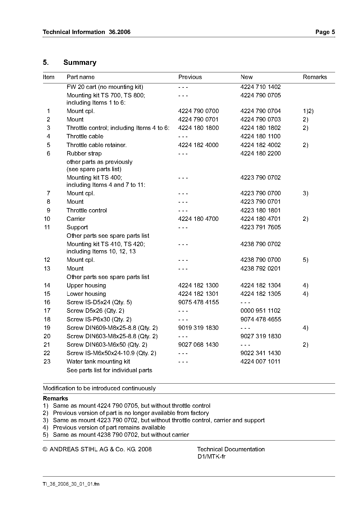
5.     Summary
Item     Part name                                   Previous            New             Remarks
         FW 20 cart (no mounting kit)                ---                 4224 710 1402
         Mounting kit TS 700, TS 800;                ---                 4224 790 0705
         including Items 1 to 6:
 1       Mount cpl.                                  4224 790 0700       4224 790 0704   1)2)
 2       Mount                                       4224 790 0701       4224 790 0703   2)
 3       Throttle control; including Items 4 to 6:   4224 180 1800       4224 180 1802   2)
 4       Throttle cable                              ---                 4224 180 1100
 5       Throttle cable retainer.                    4224 182 4000       4224 182 4002   2)
 6       Rubber strap                                ---                 4224 180 2200
         other parts as previously
         (see spare parts list)
         Mounting kit TS 400;                        ---                 4223 790 0702
         including Items 4 and 7 to 11:
 7       Mount cpl.                                  ---                 4223 790 0700   3)
 8       Mount                                       ---                 4223 790 0701
 9       Throttle control                            ---                 4223 180 1801
10       Carrier                                     4224 180 4700       4224 180 4701   2)
11       Support                                     ---                 4223 791 7605
         Other parts see spare parts list
         Mounting kit TS 410, TS 420;                ---                 4238 790 0702
         including Items 10, 12, 13
12       Mount cpl.                                  ---                 4238 790 0700   5)
13       Mount                                       ---                 4238 792 0201
         Other parts see spare parts list
14       Upper housing                               4224 182 1300       4224 182 1304   4)
15       Lower housing                               4224 182 1301       4224 182 1305   4)
16       Screw IS-D5x24 (Qty. 5)                     9075 478 4155       ---
17       Screw D5x26 (Qty. 2)                        ---                 0000 951 1102
18       Screw IS-P6x30 (Qty. 2)                     ---                 9074 478 4655
19       Screw DIN609-M8x25-8.8 (Qty. 2)             9019 319 1830       ---             4)
20       Screw DIN603-M8x25-8.8 (Qty. 2)             ---                 9027 319 1830
21       Screw DIN603-M6x50 (Qty. 2)                 9027 068 1430       ---             2)
22       Screw IS-M6x50x24-10.9 (Qty. 2)             ---                 9022 341 1430
23       Water tank mounting kit                     ---                 4224 007 1011
         See parts list for individual parts

Modification to be introduced continuously
Remarks
1) Same as mount 4224 790 0705, but without throttle control
2) Previous version of part is no longer available from factory
3) Same as mount 4223 790 0702, but without throttle control, carrier and support
4) Previous version of part remains available
5) Same as mount 4238 790 0702, but without carrier

© ANDREAS STIHL AG & Co. KG. 2008                          Technical Documentation
                                                           D1/MTK-fr

TI_36_2006_30_01_01.fm
Most of these PDFs embed fonts with a shifted character map, so the text above was recovered rather than copied — read it as a faithful but imperfect transcription, and treat the page image above each block as the authority where the two disagree — the figures exist only there, because they are vector drawings that text extraction cannot keep.