Technical Information · issue 38 of 2006
Variable-length blower unit; Variable-length, conductive blower unit (special accessory); Winter flap; Fuel hoses; Stop buffer
IssueTI 38/2006
Part changes (2)
| Was | Becomes | What the bulletin says |
|---|---|---|
| 4282 790 1300 | 4282 790 1302 | 2 Control handle Service note The previous control handle 4282 790 1300 is replaced by the new, conductive control handle 4282 790 1302. |
| 4282 791 5900 | 4282 791 5902 | The previous stop buffer 4282 791 5900 is no longer used and is replaced by the new stop buffer 4282 791 5902. |
Full text
Page 1 of 14
Text of page 1 — search, copy, screen readers
STIH)

Technical Information                                                                        38.2006

  Blower STIHL BR 500                                             Series 4282
  Blower STIHL BR 550                                             Series 4282
  Blower STIHL BR 600                                             Series 4282

  Contents
  1.   Variable-length blower tube
  2.   Variable-length, conductive blower tube (special accessory)
  3.   Winter flap
  4.   Fuel hoses
  5.   Stop buffer

  1.      Variable-length blower tube
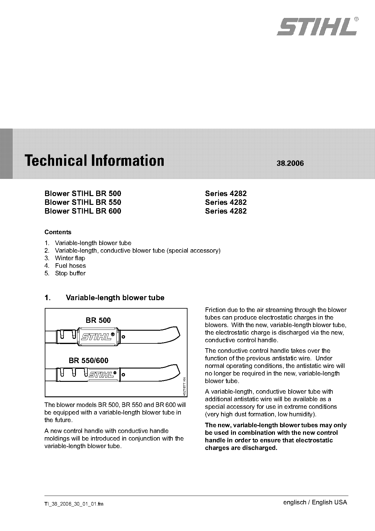
                                                                  Friction due to the air streaming through the blower
                                                                  tubes can produce electrostatic charges in the
                 BR 500
                                                                  blowers. With the new, variable-length blower tube,
                                                                  the electrostatic charge is discharged via the new,
                                                                  conductive control handle.
                                                                  The conductive control handle takes over the
           BR 550/600                                             function of the previous antistatic wire. Under
                                                                  normal operating conditions, the antistatic wire will
                                                                  no longer be required in the new, variable-length
                                                    452TI077 KN

                                                                  blower tube.
                                                                  A variable-length, conductive blower tube with
                                                                  additional antistatic wire will be available as a
  The blower models BR 500, BR 550 and BR 600 will                special accessory for use in extreme conditions
  be equipped with a variable-length blower tube in               (very high dust formation, low humidity).
  the future.
                                                                  The new, variable-length blower tubes may only
  A new control handle with conductive handle                     be used in combination with the new control
  moldings will be introduced in conjunction with the             handle in order to ensure that electrostatic
  variable-length blower tube.                                    charges are discharged.

  TI_38_2006_30_01_01.fm                                                                       englisch / English USA
Page 2 of 14
Text of page 2 — search, copy, screen readers
Page 2                                                                                          Technical Information 38.2006

1.1       Blower tubes, antistatic wire
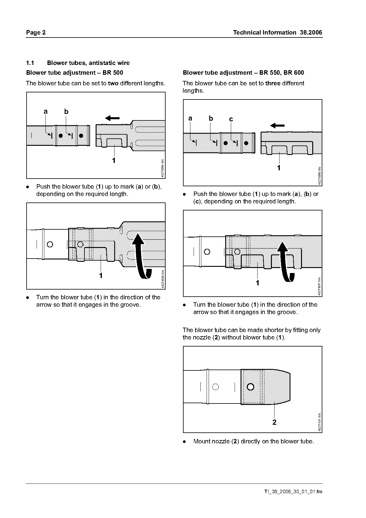
Blower tube adjustment – BR 500                                        Blower tube adjustment – BR 550, BR 600
The blower tube can be set to two different lengths.                   The blower tube can be set to three different
                                                                       lengths.

        a       b
                                                                           a        b       c

                                   1                     452TI094 KN


                                                                                                                                  452TI096 KN
.     Push the blower tube (1) up to mark (a) or (b),
      depending on the required length.                                .       Push the blower tube (1) up to mark (a), (b) or
                                                                               (c), depending on the required length.
                                                         452TI095 KN


                                                                                                                                  452TI097 KN
                                                                                                       1
.     Turn the blower tube (1) in the direction of the
      arrow so that it engages in the groove.                          .       Turn the blower tube (1) in the direction of the
                                                                               arrow so that it engages in the groove.

                                                                       The blower tube can be made shorter by fitting only
                                                                       the nozzle (2) without blower tube (1).
                                                                                                                                  452TI101 KN


                                                                       .       Mount nozzle (2) directly on the blower tube.

                                                                                                           TI_38_2006_30_01_01.fm
Page 3 of 14
Text of page 3 — search, copy, screen readers
Technical Information 38.2006                                                                          Page 3

       8                     5                                                       6
                         1                                                      3                      4

                                                                                2
                                                                                     7

       8
                         1                                                      3


                                                                                                           452TI079 KN
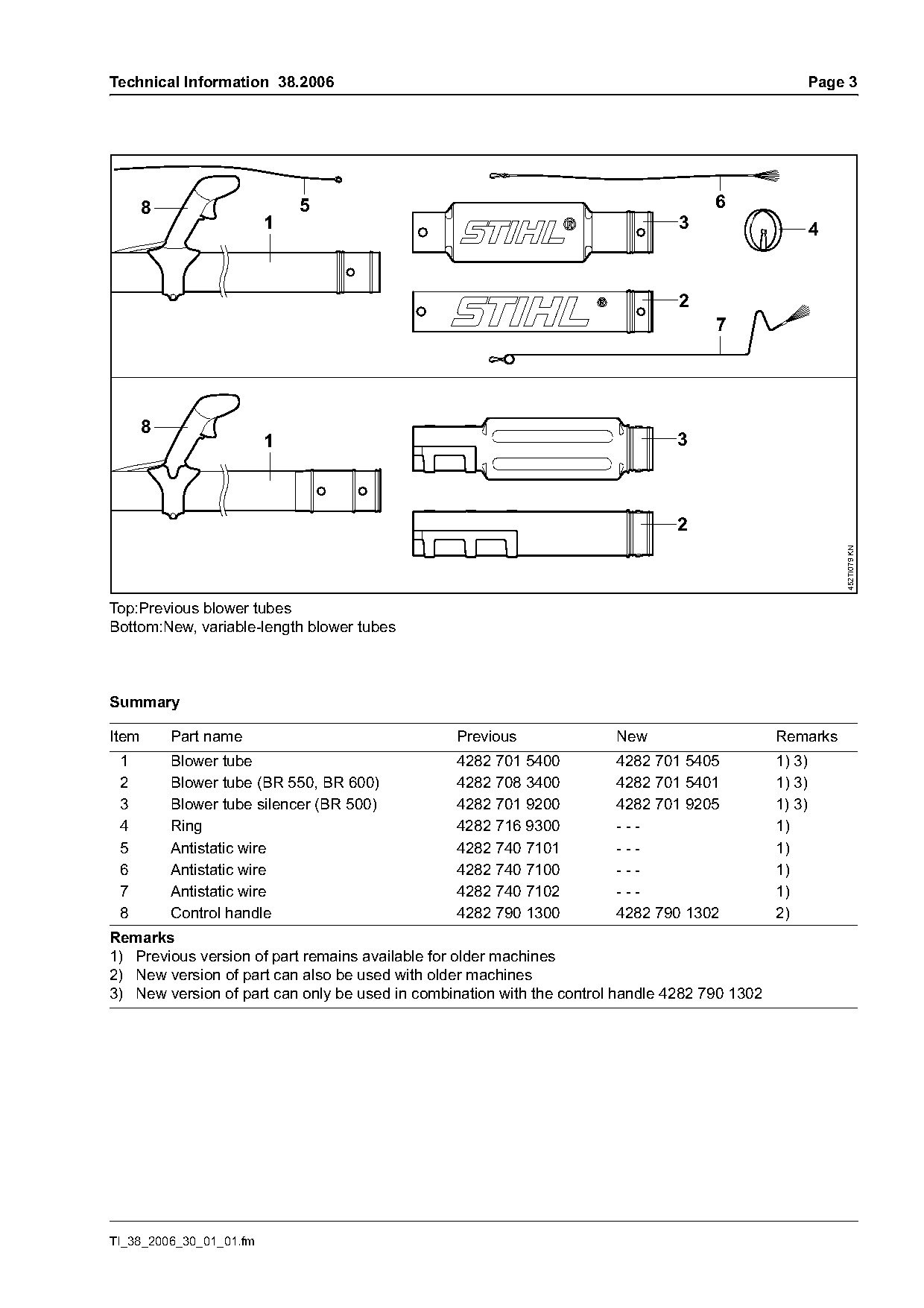
Top:Previous blower tubes
Bottom:New, variable-length blower tubes

Summary

Item       Part name                            Previous               New                     Remarks
 1         Blower tube                          4282 701 5400          4282 701 5405           1) 3)
 2         Blower tube (BR 550, BR 600)         4282 708 3400          4282 701 5401           1) 3)
 3         Blower tube silencer (BR 500)        4282 701 9200          4282 701 9205           1) 3)
 4         Ring                                 4282 716 9300          ---                     1)
 5         Antistatic wire                      4282 740 7101          ---                     1)
 6         Antistatic wire                      4282 740 7100          ---                     1)
 7         Antistatic wire                      4282 740 7102          ---                     1)
 8         Control handle                       4282 790 1300          4282 790 1302           2)
Remarks
1) Previous version of part remains available for older machines
2) New version of part can also be used with older machines
3) New version of part can only be used in combination with the control handle 4282 790 1302

TI_38_2006_30_01_01.fm
Page 4 of 14
Text of page 4 — search, copy, screen readers
Page 4                                                 Technical Information 38.2006

Service note
The new, variable-length blower tube may only be
used in combination with the new conductive control
handle 4282 790 1302.

Spare parts
The blower tubes for the previous, non-adjustable
tube assembly remain available as spare parts for
older machines.
The previous blower tubes cannot be combined with
the new adjustable blower tubes.
The antistatic wire for the previous, non-adjustable
tube assembly remains available as a spare part for
older machines. The antistatic wire is no longer
needed in the new, variable-length blower tube.
The nozzles remain unchanged.

                                                                 TI_38_2006_30_01_01.fm
Page 5 of 14
Text of page 5 — search, copy, screen readers
Technical Information 38.2006                                                                              Page 5

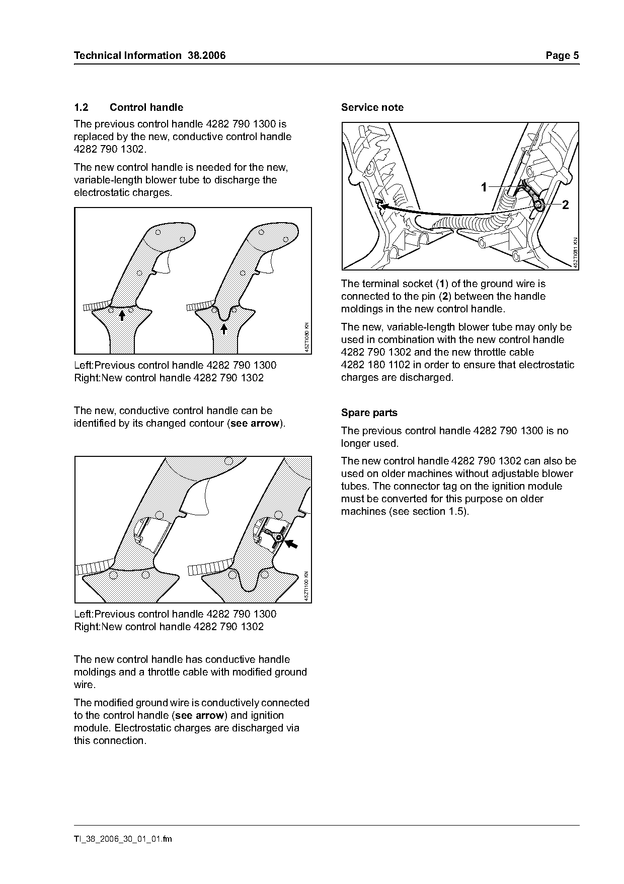
1.2    Control handle                                          Service note
The previous control handle 4282 790 1300 is
replaced by the new, conductive control handle
4282 790 1302.
The new control handle is needed for the new,
variable-length blower tube to discharge the
electrostatic charges.                                                                       1
                                                                                                               2

                                                                                                                   452TI081 KN
                                                               The terminal socket (1) of the ground wire is
                                                               connected to the pin (2) between the handle
                                                               moldings in the new control handle.
                                                               The new, variable-length blower tube may only be
                                                 452TI080 KN

                                                               used in combination with the new control handle
                                                               4282 790 1302 and the new throttle cable
Left:Previous control handle 4282 790 1300                     4282 180 1102 in order to ensure that electrostatic
Right:New control handle 4282 790 1302                         charges are discharged.

The new, conductive control handle can be                      Spare parts
identified by its changed contour (see arrow).
                                                               The previous control handle 4282 790 1300 is no
                                                               longer used.
                                                               The new control handle 4282 790 1302 can also be
                                                               used on older machines without adjustable blower
                                                               tubes. The connector tag on the ignition module
                                                               must be converted for this purpose on older
                                                               machines (see section 1.5).
                                                 452TI100 KN

Left:Previous control handle 4282 790 1300
Right:New control handle 4282 790 1302

The new control handle has conductive handle
moldings and a throttle cable with modified ground
wire.
The modified ground wire is conductively connected
to the control handle (see arrow) and ignition
module. Electrostatic charges are discharged via
this connection.

TI_38_2006_30_01_01.fm
Page 6 of 14
Text of page 6 — search, copy, screen readers
Page 6                                              Technical Information 38.2006

1.3      Handle moldings
The new control handle 4282 790 1302 has a
conductive handle molding, inner 4282 791 0803
and a conductive handle molding, outer
4282 791 0804.

Service note
The new, variable-length blower tube may only be
used in combination with the new control handle
4282 790 1302 with conductive handle moldings in
order to ensure that electrostatic charges are
discharged.

Spare parts
The previous handle molding, inner 4282 791 0800
and the previous handle molding, outer
4282 791 0801 remain available as spare parts for
the previous control handle 4282 790 1300.

                                                              TI_38_2006_30_01_01.fm
Page 7 of 14
Text of page 7 — search, copy, screen readers
Technical Information 38.2006                                                                Page 7

                         3                                        3

                                                           4                                     4

                                 5                                          5
                                                                                             6

                                                                                                     452TI082 KN
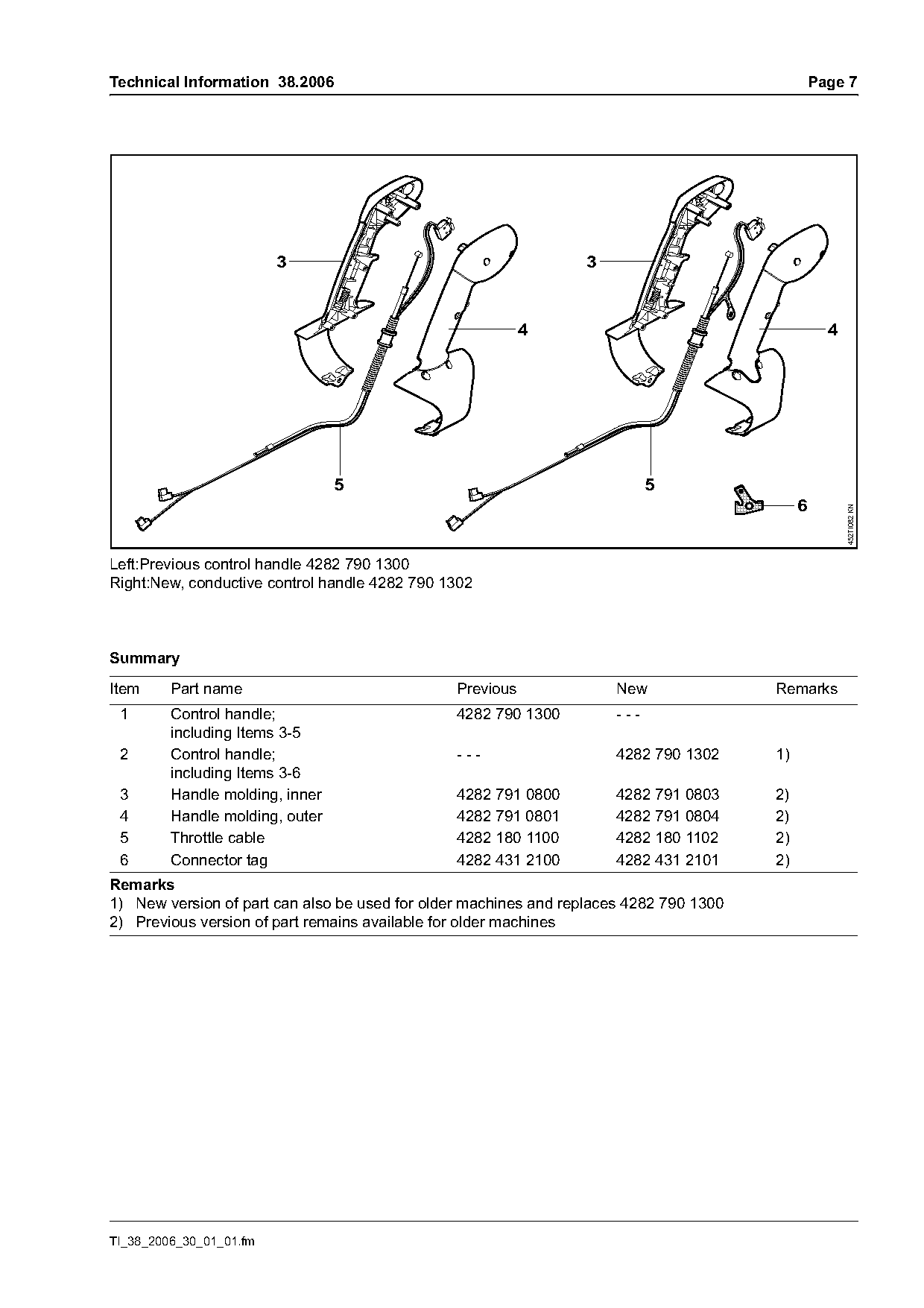
Left:Previous control handle 4282 790 1300
Right:New, conductive control handle 4282 790 1302

Summary

Item     Part name                              Previous              New               Remarks
 1       Control handle;                        4282 790 1300         ---
         including Items 3-5
 2       Control handle;                        ---                   4282 790 1302     1)
         including Items 3-6
 3       Handle molding, inner                  4282 791 0800         4282 791 0803     2)
 4       Handle molding, outer                  4282 791 0801         4282 791 0804     2)
 5       Throttle cable                         4282 180 1100         4282 180 1102     2)
 6       Connector tag                          4282 431 2100         4282 431 2101     2)
Remarks
1) New version of part can also be used for older machines and replaces 4282 790 1300
2) Previous version of part remains available for older machines

TI_38_2006_30_01_01.fm
Page 8 of 14
Text of page 8 — search, copy, screen readers
Page 8                                                                            Technical Information 38.2006

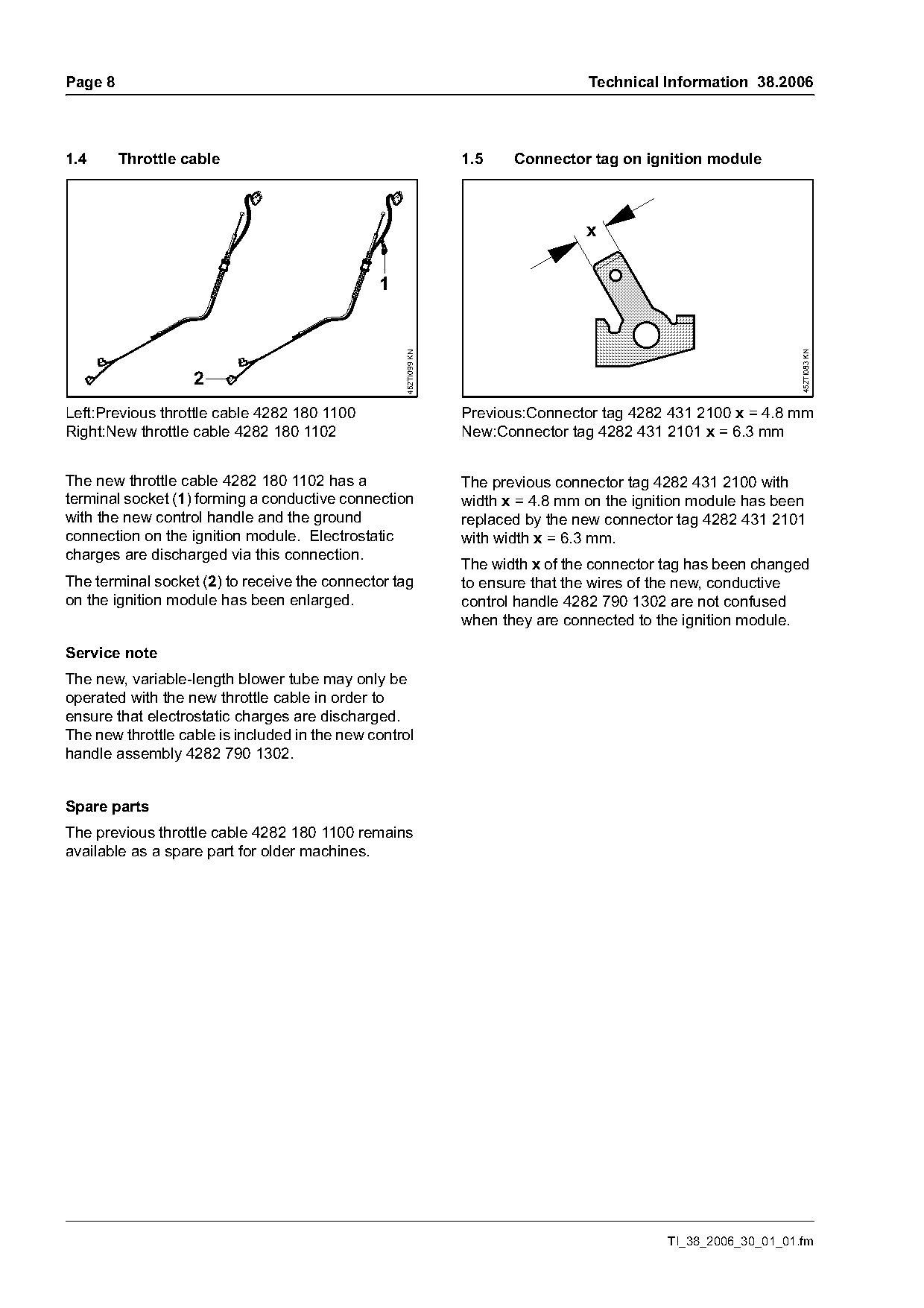
1.4      Throttle cable                                          1.5    Connector tag on ignition module


                                                                                                                  452TI083 KN
                                                   452TI099 KN
                   2
Left:Previous throttle cable 4282 180 1100                       Previous:Connector tag 4282 431 2100 x = 4.8 mm
Right:New throttle cable 4282 180 1102                           New:Connector tag 4282 431 2101 x = 6.3 mm

The new throttle cable 4282 180 1102 has a                       The previous connector tag 4282 431 2100 with
terminal socket (1) forming a conductive connection              width x = 4.8 mm on the ignition module has been
with the new control handle and the ground                       replaced by the new connector tag 4282 431 2101
connection on the ignition module. Electrostatic                 with width x = 6.3 mm.
charges are discharged via this connection.
                                                                 The width x of the connector tag has been changed
The terminal socket (2) to receive the connector tag             to ensure that the wires of the new, conductive
on the ignition module has been enlarged.                        control handle 4282 790 1302 are not confused
                                                                 when they are connected to the ignition module.

Service note
The new, variable-length blower tube may only be
operated with the new throttle cable in order to
ensure that electrostatic charges are discharged.
The new throttle cable is included in the new control
handle assembly 4282 790 1302.

Spare parts
The previous throttle cable 4282 180 1100 remains
available as a spare part for older machines.

                                                                                              TI_38_2006_30_01_01.fm
Page 9 of 14
Text of page 9 — search, copy, screen readers
Technical Information 38.2006                                                                                  Page 9

Service note                                                    2.       Variable-length, conductive
                                                                         blower tube (special accessory)
                                                                A variable-length blower tube with conductive
                                                                blower tubes is available as a special accessory for
               1                                                use in extreme conditions (very high dust formation,
                                                                low humidity).
               2
                                                                The blower tube additionally includes an antistatic
 3                                                              wire.

                                                  452TI084 KN
                                                                Service note
                                                                The variable-length, conductive blower tube may
                                                                only be used with:
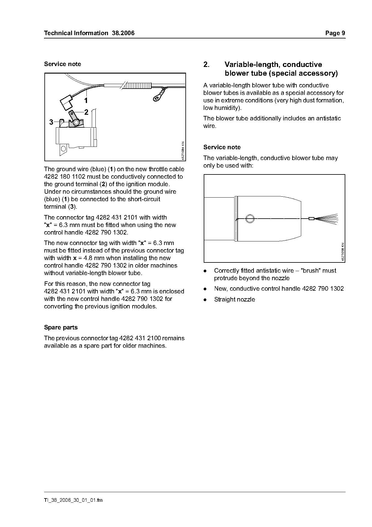
The ground wire (blue) (1) on the new throttle cable
4282 180 1102 must be conductively connected to
the ground terminal (2) of the ignition module.
Under no circumstances should the ground wire
(blue) (1) be connected to the short-circuit
terminal (3).
The connector tag 4282 431 2101 with width
"x" = 6.3 mm must be fitted when using the new
control handle 4282 790 1302.
The new connector tag with width "x" = 6.3 mm

                                                                                                                       452TI098 KN
must be fitted instead of the previous connector tag
with width x = 4.8 mm when installing the new
control handle 4282 790 1302 in older machines
without variable-length blower tube.                            .    Correctly fitted antistatic wire – "brush" must
                                                                     protrude beyond the nozzle
For this reason, the new connector tag
4282 431 2101 with width "x" = 6.3 mm is enclosed               .    New, conductive control handle 4282 790 1302
with the new control handle 4282 790 1302 for                   .    Straight nozzle
converting the previous ignition modules.

Spare parts
The previous connector tag 4282 431 2100 remains
available as a spare part for older machines.

TI_38_2006_30_01_01.fm
Page 10 of 14
Text of page 10 — search, copy, screen readers
Page 10                                                                 Technical Information 38.2006

              10
                                                           6                                  8
                                                                              7


                                                           5                  7               9

                                                                                                        452TI085 KN
Summary

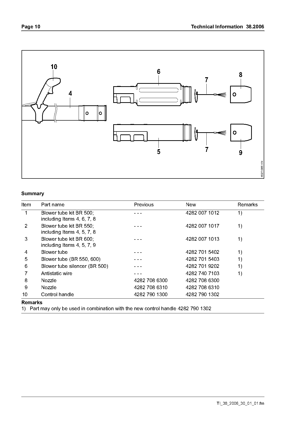
Item      Part name                             Previous              New                    Remarks
 1        Blower tube kit BR 500;               ---                   4282 007 1012          1)
          including Items 4, 6, 7, 8
 2        Blower tube kit BR 550;               ---                   4282 007 1017          1)
          including Items 4, 5, 7, 8
 3        Blower tube kit BR 600;               ---                   4282 007 1013          1)
          including Items 4, 5, 7, 9
 4        Blower tube                           ---                   4282 701 5402          1)
 5        Blower tube (BR 550, 600)             ---                   4282 701 5403          1)
 6        Blower tube silencer (BR 500)         ---                   4282 701 9202          1)
 7        Antistatic wire                       ---                   4282 740 7103          1)
 8        Nozzle                                4282 708 6300         4282 708 6300
 9        Nozzle                                4282 708 6310         4282 708 6310
10        Control handle                        4282 790 1300         4282 790 1302
Remarks
1) Part may only be used in combination with the new control handle 4282 790 1302

                                                                                    TI_38_2006_30_01_01.fm
Page 11 of 14
Text of page 11 — search, copy, screen readers
Technical Information 38.2006                                                                                    Page 11

3.      Winter flap
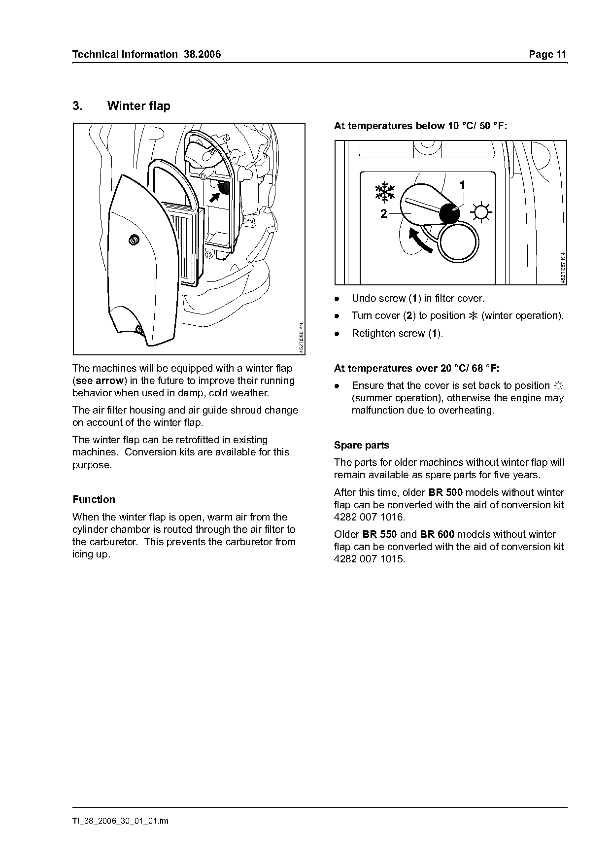
                                                                     At temperatures below 10 °C/ 50 °F:


                                                                                                                         452TI087 KN
                                                                     .   Undo screw (1) in filter cover.
                                                                     .   Turn cover (2) to position r (winter operation).
                                                       452TI086 KN

                                                                     .   Retighten screw (1).

The machines will be equipped with a winter flap                     At temperatures over 20 °C/ 68 °F:
(see arrow) in the future to improve their running                   .   Ensure that the cover is set back to position s
behavior when used in damp, cold weather.                                (summer operation), otherwise the engine may
The air filter housing and air guide shroud change                       malfunction due to overheating.
on account of the winter flap.
The winter flap can be retrofitted in existing
                                                                     Spare parts
machines. Conversion kits are available for this
purpose.                                                             The parts for older machines without winter flap will
                                                                     remain available as spare parts for five years.
                                                                     After this time, older BR 500 models without winter
Function
                                                                     flap can be converted with the aid of conversion kit
When the winter flap is open, warm air from the                      4282 007 1016.
cylinder chamber is routed through the air filter to                 Older BR 550 and BR 600 models without winter
the carburetor. This prevents the carburetor from                    flap can be converted with the aid of conversion kit
icing up.                                                            4282 007 1015.

TI_38_2006_30_01_01.fm
Page 12 of 14
Text of page 12 — search, copy, screen readers
Page 12                                                                     Technical Information 38.2006

                                                                    8   7

                                1, 2          3                                    4, 5        6

                                                                                                          452TI088 KN
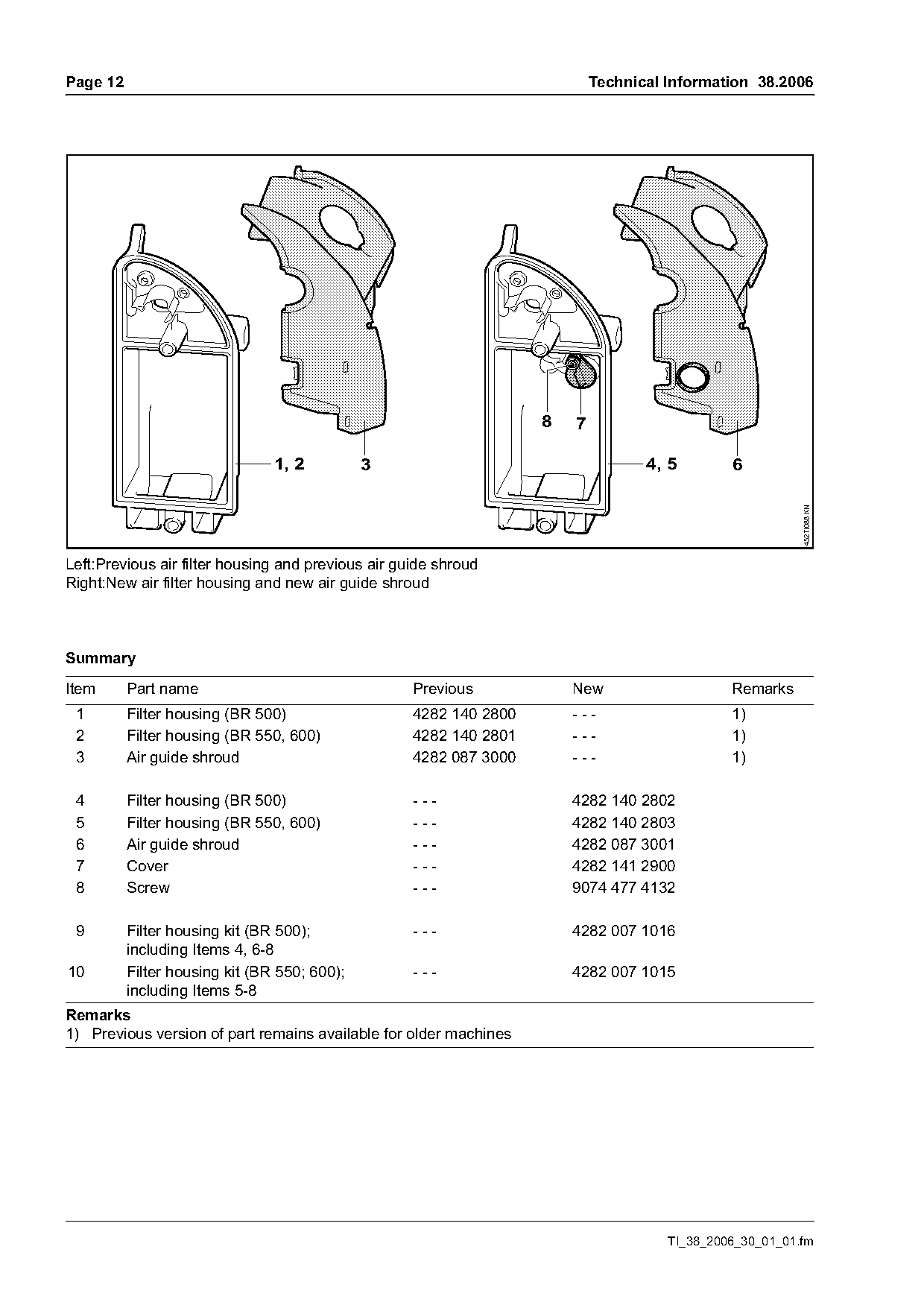
Left:Previous air filter housing and previous air guide shroud
Right:New air filter housing and new air guide shroud

Summary

Item      Part name                                 Previous            New                    Remarks
 1        Filter housing (BR 500)                   4282 140 2800       ---                    1)
 2        Filter housing (BR 550, 600)              4282 140 2801       ---                    1)
 3        Air guide shroud                          4282 087 3000       ---                    1)

 4        Filter housing (BR 500)                   ---                 4282 140 2802
 5        Filter housing (BR 550, 600)              ---                 4282 140 2803
 6        Air guide shroud                          ---                 4282 087 3001
 7        Cover                                     ---                 4282 141 2900
 8        Screw                                     ---                 9074 477 4132

 9        Filter housing kit (BR 500);              ---                 4282 007 1016
          including Items 4, 6-8
10        Filter housing kit (BR 550; 600);         ---                 4282 007 1015
          including Items 5-8
Remarks
1) Previous version of part remains available for older machines

                                                                                      TI_38_2006_30_01_01.fm
Page 13 of 14
Text of page 13 — search, copy, screen readers
Technical Information 38.2006                                                                                 Page 13

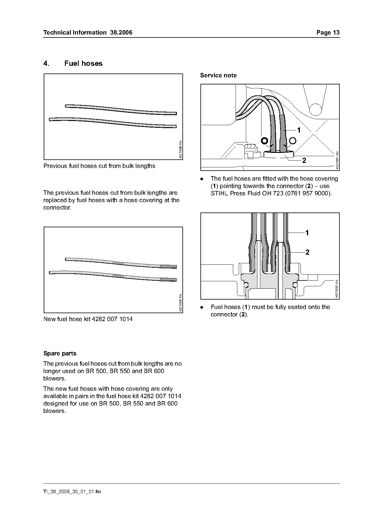
4.      Fuel hoses
                                                                  Service note


                                                    452TI089 KN

                                                                                                                       452TI091 KN
                                                                                                          2
Previous fuel hoses cut from bulk lengths

                                                                  .   The fuel hoses are fitted with the hose covering
                                                                      (1) pointing towards the connector (2) – use
The previous fuel hoses cut from bulk lengths are                     STIHL Press Fluid OH 723 (0781 957 9000).
replaced by fuel hoses with a hose covering at the
connector.


                                                                                                                     452TI092 KN
                                                    452TI090 KN

                                                                  .   Fuel hoses (1) must be fully seated onto the
                                                                      connector (2).
New fuel hose kit 4282 007 1014

Spare parts
The previous fuel hoses cut from bulk lengths are no
longer used on BR 500, BR 550 and BR 600
blowers.
The new fuel hoses with hose covering are only
available in pairs in the fuel hose kit 4282 007 1014
designed for use on BR 500, BR 550 and BR 600
blowers.

TI_38_2006_30_01_01.fm
Page 14 of 14
Text of page 14 — search, copy, screen readers
Page 14                                                                           Technical Information 38.2006

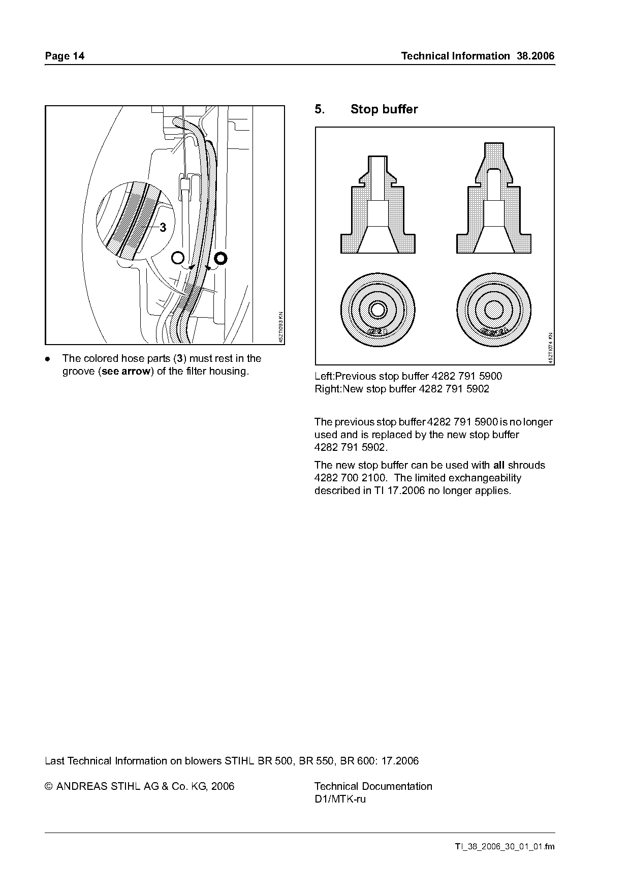
                                                                5.     Stop buffer


                                                  452TI093 KN

                                                                                                                   452TI074 KN
.   The colored hose parts (3) must rest in the
    groove (see arrow) of the filter housing.                   Left:Previous stop buffer 4282 791 5900
                                                                Right:New stop buffer 4282 791 5902

                                                                The previous stop buffer 4282 791 5900 is no longer
                                                                used and is replaced by the new stop buffer
                                                                4282 791 5902.
                                                                The new stop buffer can be used with all shrouds
                                                                4282 700 2100. The limited exchangeability
                                                                described in TI 17.2006 no longer applies.

Last Technical Information on blowers STIHL BR 500, BR 550, BR 600: 17.2006

© ANDREAS STIHL AG & Co. KG, 2006                               Technical Documentation
                                                                D1/MTK-ru

                                                                                              TI_38_2006_30_01_01.fm
Most of these PDFs embed fonts with a shifted character map, so the text above was recovered rather than copied — read it as a faithful but imperfect transcription, and treat the page image above each block as the authority where the two disagree — the figures exist only there, because they are vector drawings that text extraction cannot keep.