Technical Information · issue 47 of 2006
New STIHL HT 250 Pole Pruner
IssueTI 47/2006
Full text
Page 1 of 6
Text of page 1 — search, copy, screen readers
STIH)

Technical Information                          47.2006

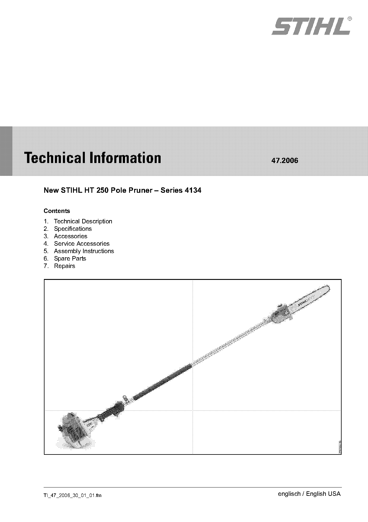
  New STIHL HT 250 Pole Pruner – Series 4134

  Contents
  1.   Technical Description
  2.   Specifications
  3.   Accessories
  4.   Service Accessories
  5.   Assembly Instructions
  6.   Spare Parts
  7.   Repairs

  TI_47_2006_30_01_01.fm                        englisch / English USA
Page 2 of 6
Text of page 2 — search, copy, screen readers
Page 2                                                                   Technical Information 47.2006

The new HT 250 pole pruner extends the line of        2.      Specifications
fixed length pole pruners.
The new unit is characterized by a high chain speed   2.1     Engine
and high torque.                                      STIHL single cylinder two-stroke engine
Applications are the same as those of model HT 100    Displacement:            2.45 cu.in (40.2 cm3)
and HT 130 pole pruners.                              Bore:                    1.57 in (40 mm)
                                                      Stroke:                  1.26 in (32 mm)
                                                      Engine power to          2.1 bhp (1.6 kW)
1.        Technical Description                       ISO 8893:                at 9,000 rpm
                                                      Idle speed:              2,800 rpm
The powerhead and controls are the same as those
                                                      Rewind starter:          Single pawl system
of the FS 250 R brushcutter.
                                                      Starter rope:            0.120 in dia.,
.     Much higher chain speed for smoother cutting                             33.5 in long
      performance                                                              (3.0 mm dia., 850 mm)
.     Powerful engine with high torque                Clutch engages at:       4,300 rpm
                                                      Cut-off speed range
1.1       Controls                                    without cutting
.     Ergonomic control handle.                       attachment:              11,300 – 13,300 rpm
                                                      Max. speed of output
.     Control handle with integral throttle cable
                                                      shaft (chain sprocket):  12,300 rpm
      adjuster.

                                                      2.2     Ignition System
The shaft and gearbox are the same as those of the    Ignition module:          with integral electronic
HT 130 pole pruner.                                                             speed governor
                                                      Spark plug                Bosch WSR 6F,
1.2       Boom (Drive Tube)
                                                      (resistor type):          NGK BPMR 7A
.     Boom with flexible drive shaft.                 Electrode gap:            0.020 in (0.5 mm)
.     Reach about 11‘ 5“ (3.5 m)

1.3       Gearbox                                     2.3     Fuel System
.     Gear ratio: 1:1                                 The STIHL engine features gasoline-oil lubrication
.     Oil tank with toolless cap                      and must be run on a fuel mixture of gasoline and
                                                      air cooled two-cycle engine oil.
1.4       Standard Cutting Attachment                 Fuel:
.     Length: 14“ (35 cm)                             see instruction manual
.     Saw chain: PMN                                  Fuel tank capacity:
                                                      21.6 oz. (640 cm3)

                                                                                    TI_47_2006_30_01_01.fm
Page 3 of 6
Text of page 3 — search, copy, screen readers
Technical Information 47.2006                                                                     Page 3

Carburetor:                                          2.6     Cutting Attachment
All position diaphragm carburetor (C1Q-S83) with
                                                     Gear ratio:                  1:1
integral fuel pump.
                                                     Guide bar:                   Rollomatic with
For carburetor adjustment see TI 09.2003 (FS 250).
                                                                                  nose sprocket
Low speed screw L            Open 1 full turn        Cutting length:              14“ (35 cm),
                                                                                  12“ (30 cm), option
High speed screw H                                   Oilomatic chain:             Picco-Micro-Mini
(standard setting with caps): Open 3/4 turn (no      Pitch:                       3/8"P (9.32 mm)
                              further than stop)     Drive link gauge             .043“ (1.1 mm)
                                                     Chain sprocket:              Spur sprocket
(Basic setting without caps): Open 1 1/2 turns       Pitch:                       3/8"P (9.32 mm)
                                                     No. of teeth:                6,
2.4      Weight                                                                   7 (option)
Dry, without cutting                                 Chain lubrication:           Fully automatic,
attachment                                                                        speed-controlled
                                                                                  rotary piston oil pump
HT 250:                      13.4 lbs. (6.1 kg)
                                                     Oil tank capacity:           7.4 oz. (220 cm3)
2.5      Length (with cutting attachment)
HT 250                       approx. 7‘ (214 cm)

3.       Accessories
Shoulder Strap
Shoulder strap 4130 710 9000 can be used with the
HT 250.

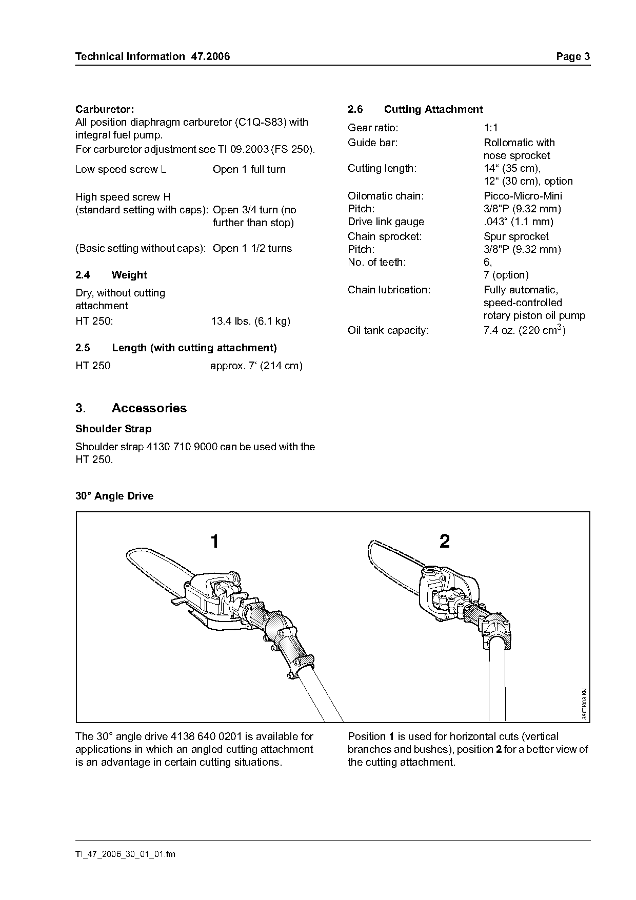
30° Angle Drive

                             1                                            2

                                                                                                        386TI003 KN

The 30° angle drive 4138 640 0201 is available for   Position 1 is used for horizontal cuts (vertical
applications in which an angled cutting attachment   branches and bushes), position 2 for a better view of
is an advantage in certain cutting situations.       the cutting attachment.

TI_47_2006_30_01_01.fm
Page 4 of 6
Text of page 4 — search, copy, screen readers
Page 4                                                                               Technical Information 47.2006

4.       Service Accessories

4.1      Special Servicing Tools
Special tools are listed in the shop manual for
models STIHL FS 120, 200, 350, 450.

4.2      Servicing Aids

Part Name                             Part No.                         Application
Set of gaskets                        4134 007 1050                    Engine
Carburetor parts kit                  1129 007 1062                    Carburetor
Lubricating grease (8 oz/225 g        0781 120 1111                    Oil seals
tube)
Gear lubricant                        0781 120 1004                    Gearbox
Gear lubricant (2.8 oz/80 g tube),    0781 120 1109,                   Drive shaft
Gear lubricant (8 oz/225 g tube)      0781 120 1110
Special lubricating oil               0781 417 1315                    Rewind spring and bearing bore in rope rotor
Dirko HT red sealant                  0783 830 2000                    Sealing engine pan/cylinder
(3.2 oz / 90g tube)
STIHL Degreaser                       7010 881 9401                    Cleaning crankshaft stub and taper on flywheel
(32 US fl.oz. bottle, 6 per carton)

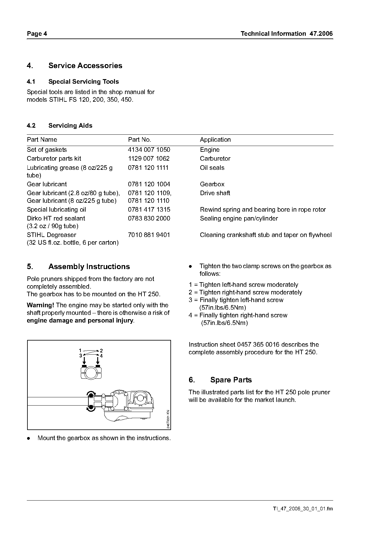
5.       Assembly Instructions                                    .    Tighten the two clamp screws on the gearbox as
                                                                       follows:
Pole pruners shipped from the factory are not
completely assembled.                                             1 = Tighten left-hand screw moderately
The gearbox has to be mounted on the HT 250.                      2 = Tighten right-hand screw moderately
                                                                  3 = Finally tighten left-hand screw
Warning! The engine may be started only with the                      (57in.lbs/6.5Nm)
shaft properly mounted – there is otherwise a risk of             4 = Finally tighten right-hand screw
engine damage and personal injury.                                     (57in.lbs/6.5Nm)

                                                                  Instruction sheet 0457 365 0016 describes the
                    1      2                                      complete assembly procedure for the HT 250.
                    3      4

                                                                  6.      Spare Parts
                                                                  The illustrated parts list for the HT 250 pole pruner
                                                                  will be available for the market launch.
                                                    246TI001 KN

.     Mount the gearbox as shown in the instructions.

                                                                                                 TI_47_2006_30_01_01.fm
Page 5 of 6
Text of page 5 — search, copy, screen readers
Technical Information 47.2006                                                                              Page 5

7.        Repairs
If the machine is started up in the course of                         Repair Description                    HT 250
repairs, it is essential to observe all country-                  2   Replace crankcase, crankcase           100
specific safety regulations and the safety                            gasket or re-seal crankcase.
precautions outlined in the instruction manual.                       Includes air leak test.
                                                                  3   Replace crankshaft main bearing(s).    100
7.1     Service Note                                                  Includes air leak test.
For servicing and repair procedures on the engine                 4   Replace crankshaft seal(s).             60
refer to the shop manual for the STIHL FS 120, 200,                   Includes air leak test.
300, 350, 400, 450; see also STIHL Service Training               5   Perform engine air leak test.           40
System "Diagnosis".                                               6   Replace cylinder and/or piston.         55
For the gearbox see the STIHL CombiTool service                       Includes air leak test and repair of
manual.                                                               component(s) causing failure.
                                                                  7   Replace ignition module or flywheel.    20
7.2     Tightening Torques                                            Includes stop circuit test.
Tightening torques for the engine, shaft and                      8   Replace fuel tank line, tank vent, or   10
gearbox are listed in the respective shop manuals.                    fuel pick-up body.
                                                                  9   Replace intake manifold or intake       20
7.3       Replacing the Gearbox                                       flange.
Use only the new gearbox 4182 640 0104 as a                      10   Repair or replace carburetor.           30
replacement. The gearbox is marked “0104”.                            Includes fuel system testing.
Use gear lubricant 0781 120 1004 for lubrication of              11   Repair throttle control.                25
the gearbox.                                                     12   Repair or replace rewind starter.       15
                                                                 13   Repair or replace clutch, clutch        20
.     Quantity of gear lubricant: 0.4 oz. (12 g)
                                                                      shoes or clutch springs.
                                                                 14   Replace muffler.                        15
                                                                 15   Replace air filter or filter housing.   10
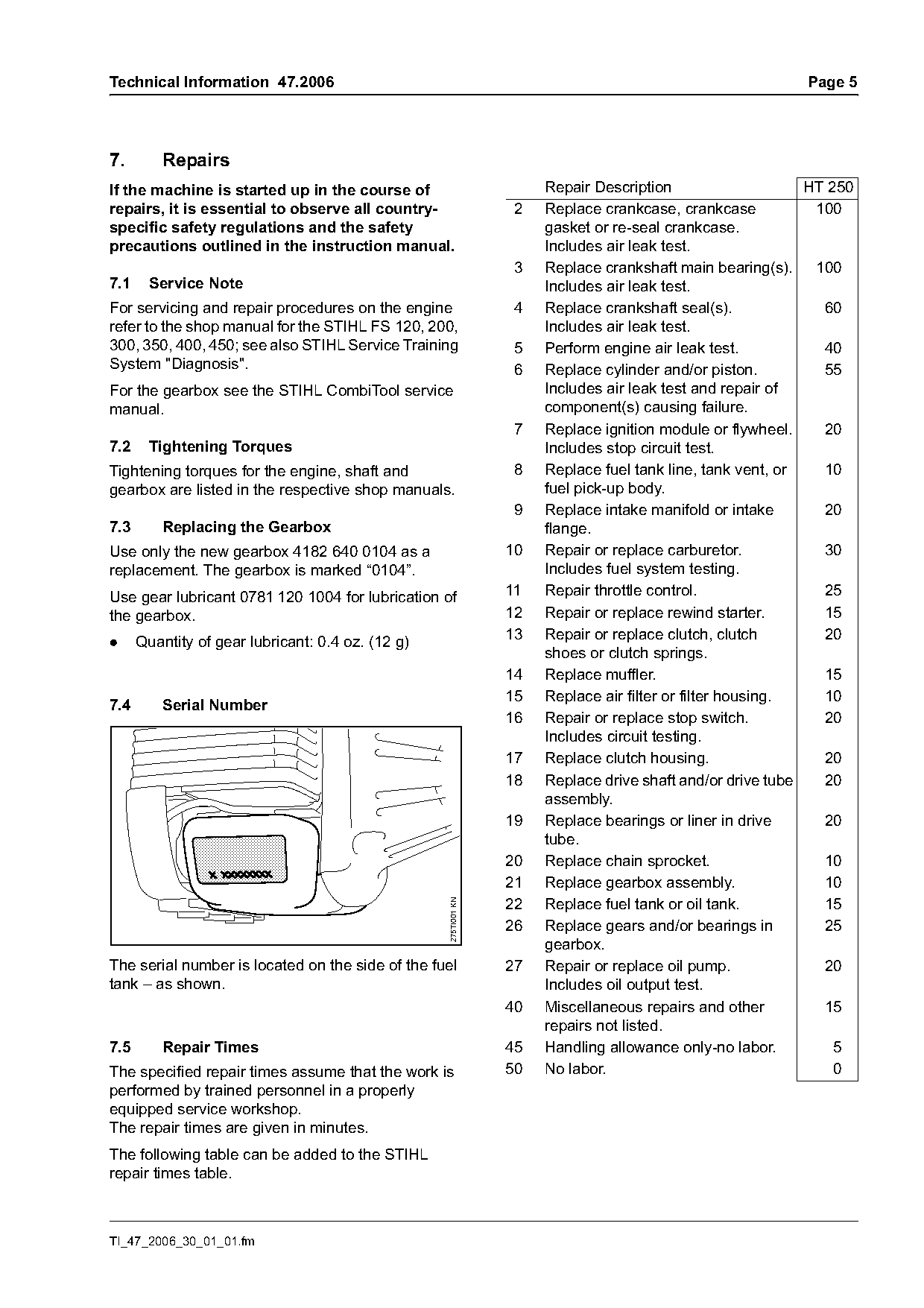
7.4       Serial Number
                                                                 16   Repair or replace stop switch.          20
                                                                      Includes circuit testing.
                                                                 17   Replace clutch housing.                 20
                                                                 18   Replace drive shaft and/or drive tube   20
                                                                      assembly.
                                                                 19   Replace bearings or liner in drive      20
                                                                      tube.
                                                                 20   Replace chain sprocket.                 10
                                                                 21   Replace gearbox assembly.               10
                                                                 22   Replace fuel tank or oil tank.          15
                                                   275TI001 KN

                                                                 26   Replace gears and/or bearings in        25
                                                                      gearbox.
The serial number is located on the side of the fuel             27   Repair or replace oil pump.             20
tank – as shown.                                                      Includes oil output test.
                                                                 40   Miscellaneous repairs and other         15
                                                                      repairs not listed.
7.5       Repair Times                                           45   Handling allowance only-no labor.         5
The specified repair times assume that the work is               50   No labor.                                 0
performed by trained personnel in a properly
equipped service workshop.
The repair times are given in minutes.
The following table can be added to the STIHL
repair times table.

TI_47_2006_30_01_01.fm
Page 6 of 6
Text of page 6 — search, copy, screen readers
Page 6                                              Technical Information 47.2006

© ANDREAS STIHL AG & Co. KG, 2006   Technical Documentation
                                    D1/MTK-ja

                                                              TI_47_2006_30_01_01.fm
Most of these PDFs embed fonts with a shifted character map, so the text above was recovered rather than copied — read it as a faithful but imperfect transcription, and treat the page image above each block as the authority where the two disagree — the figures exist only there, because they are vector drawings that text extraction cannot keep.