Technical Information · issue 50 of 2006
1. Assembly stand; 2. Clamping rail; 3. Screwdriver; 4. Summary
IssueTI 50/2006
Part changes (2)
| Was | Becomes | What the bulletin says |
|---|---|---|
| 5910 890 3100 | 5910 890 3101 | Assembly stand The previous assembly stand 5910 890 3100 with welded-on support has been replaced by the version 5910 890 3101. |
| 5910 890 2000 | 5910 850 1650 | The previous clamping rail 5910 890 2000 is no longer used and is instead replaced by the generally usable kit "Support 5910 850 1650". |
Full text
Page 1 of 5
Text of page 1 — search, copy, screen readers
STIH)

Technical Information                                                      50.2006

  New STIHL special tools

  Contents
  1.   Assembly stand
  2.   Clamping rail
  3.   Screwdriver
  4.   Summary

  1.      Assembly stand
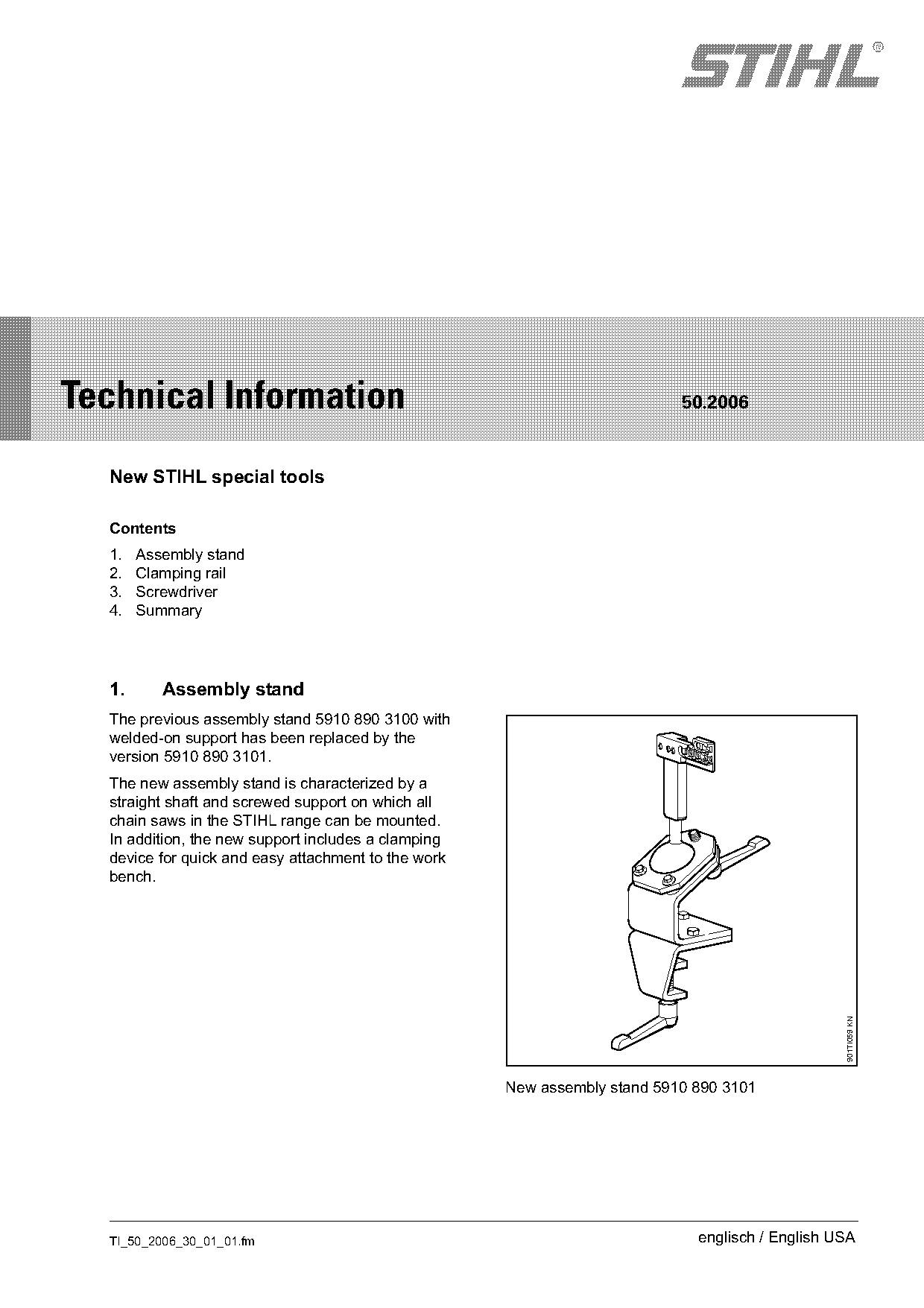
  The previous assembly stand 5910 890 3100 with
  welded-on support has been replaced by the
  version 5910 890 3101.
  The new assembly stand is characterized by a
  straight shaft and screwed support on which all
  chain saws in the STIHL range can be mounted.
  In addition, the new support includes a clamping
  device for quick and easy attachment to the work
  bench.
                                                                                                 901TI059 KN

                                                     New assembly stand 5910 890 3101

  TI_50_2006_30_01_01.fm                                                     englisch / English USA
Page 2 of 5
Text of page 2 — search, copy, screen readers
Page 2                                                                            Technical Information 50.2006

1.1      Support                                                1.2    Clamping plate
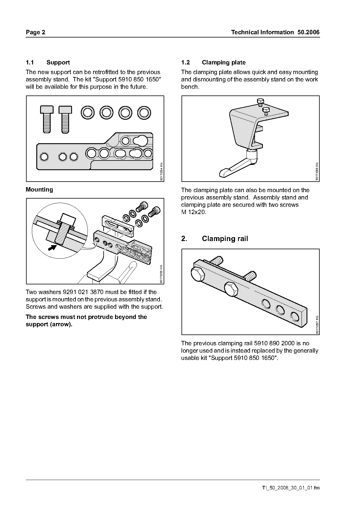
The new support can be retrofitted to the previous              The clamping plate allows quick and easy mounting
assembly stand. The kit "Support 5910 850 1650"                 and dismounting of the assembly stand on the work
will be available for this purpose in the future.               bench.

                                                                                                                  901TI056 KN
                                                  901TI054 KN

Mounting                                                        The clamping plate can also be mounted on the
                                                                previous assembly stand. Assembly stand and
                                                                clamping plate are secured with two screws
                                                                M 12x20.

                                                                2.     Clamping rail
                                                 901TI055 KN

Two washers 9291 021 3870 must be fitted if the
support is mounted on the previous assembly stand.
Screws and washers are supplied with the support.
The screws must not protrude beyond the                                                                           901TI057 KN

support (arrow).

                                                                The previous clamping rail 5910 890 2000 is no
                                                                longer used and is instead replaced by the generally
                                                                usable kit "Support 5910 850 1650".

                                                                                              TI_50_2006_30_01_01.fm
Page 3 of 5
Text of page 3 — search, copy, screen readers
Technical Information 50.2006                                                                                    Page 3

3.      Screwdriver                                              3.1       Service work

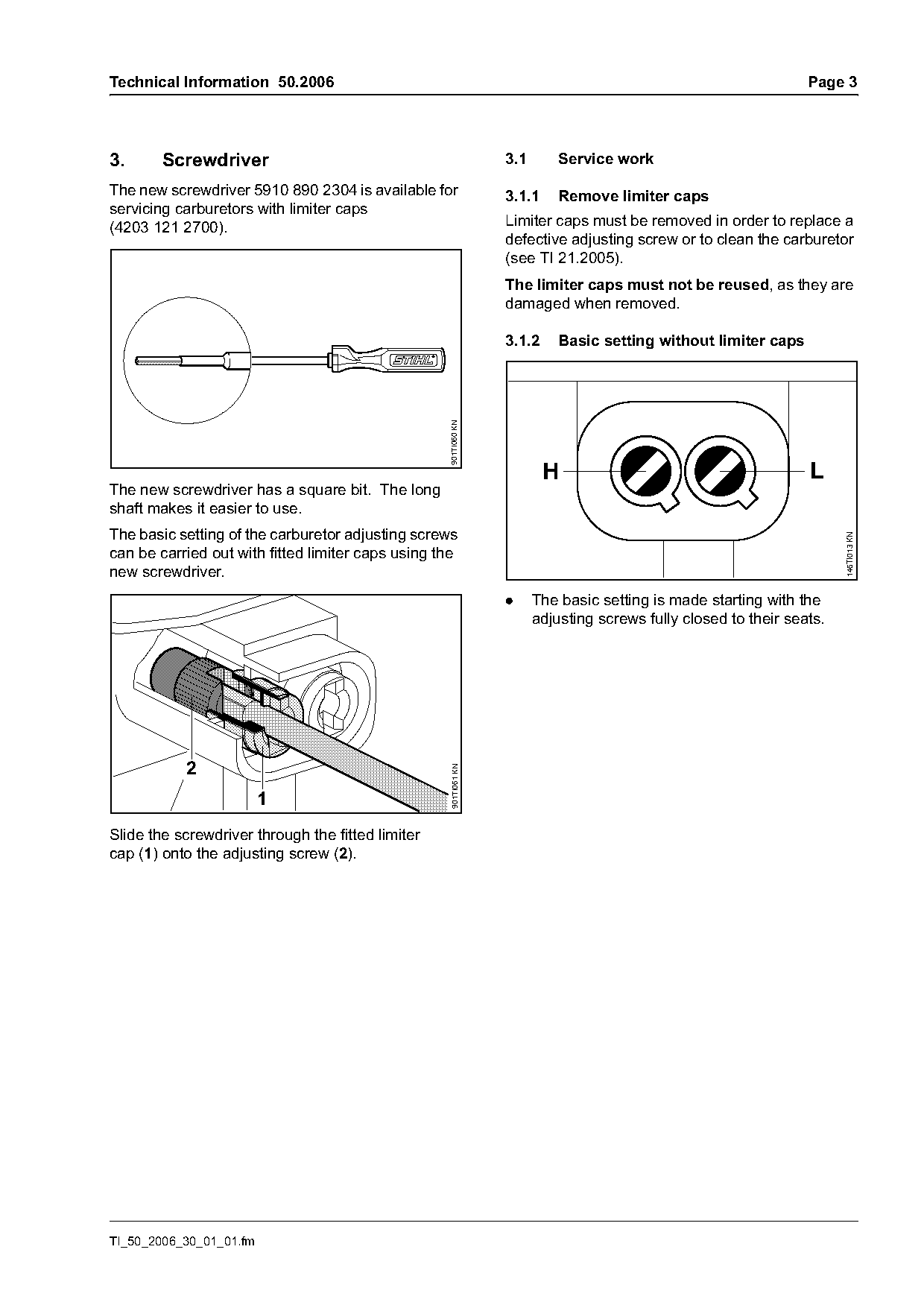
The new screwdriver 5910 890 2304 is available for               3.1.1     Remove limiter caps
servicing carburetors with limiter caps
(4203 121 2700).                                                 Limiter caps must be removed in order to replace a
                                                                 defective adjusting screw or to clean the carburetor
                                                                 (see TI 21.2005).
                                                                 The limiter caps must not be reused, as they are
                                                                 damaged when removed.

                                                                 3.1.2     Basic setting without limiter caps

                                                   901TI060 KN

                                                                         H                                       L
The new screwdriver has a square bit. The long
shaft makes it easier to use.
The basic setting of the carburetor adjusting screws

                                                                                                                       146TI013 KN
can be carried out with fitted limiter caps using the
new screwdriver.
                                                                 .     The basic setting is made starting with the
                                                                       adjusting screws fully closed to their seats.

           2
                                                   901TI061 KN

                         1
Slide the screwdriver through the fitted limiter
cap (1) onto the adjusting screw (2).

TI_50_2006_30_01_01.fm
Page 4 of 5
Text of page 4 — search, copy, screen readers
Page 4                                                                                     Technical Information 50.2006

3.2       Fit limiter caps                                            3.3       Basic setting with fitted limiter caps

                                                        901TI062 KN

                                                                                                                           001TI008 KN
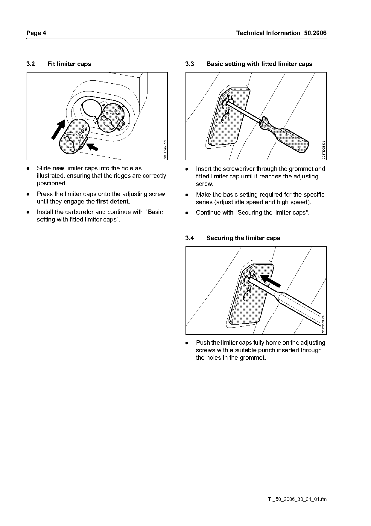
.     Slide new limiter caps into the hole as                         .     Insert the screwdriver through the grommet and
      illustrated, ensuring that the ridges are correctly                   fitted limiter cap until it reaches the adjusting
      positioned.                                                           screw.
.     Press the limiter caps onto the adjusting screw                 .     Make the basic setting required for the specific
      until they engage the first detent.                                   series (adjust idle speed and high speed).
.     Install the carburetor and continue with "Basic                 .     Continue with "Securing the limiter caps".
      setting with fitted limiter caps".

                                                                      3.4       Securing the limiter caps

                                                                                                                           001TI009 KN

                                                                      .     Push the limiter caps fully home on the adjusting
                                                                            screws with a suitable punch inserted through
                                                                            the holes in the grommet.

                                                                                                       TI_50_2006_30_01_01.fm
Page 5 of 5
Text of page 5 — search, copy, screen readers
Technical Information 50.2006                                                                     Page 5

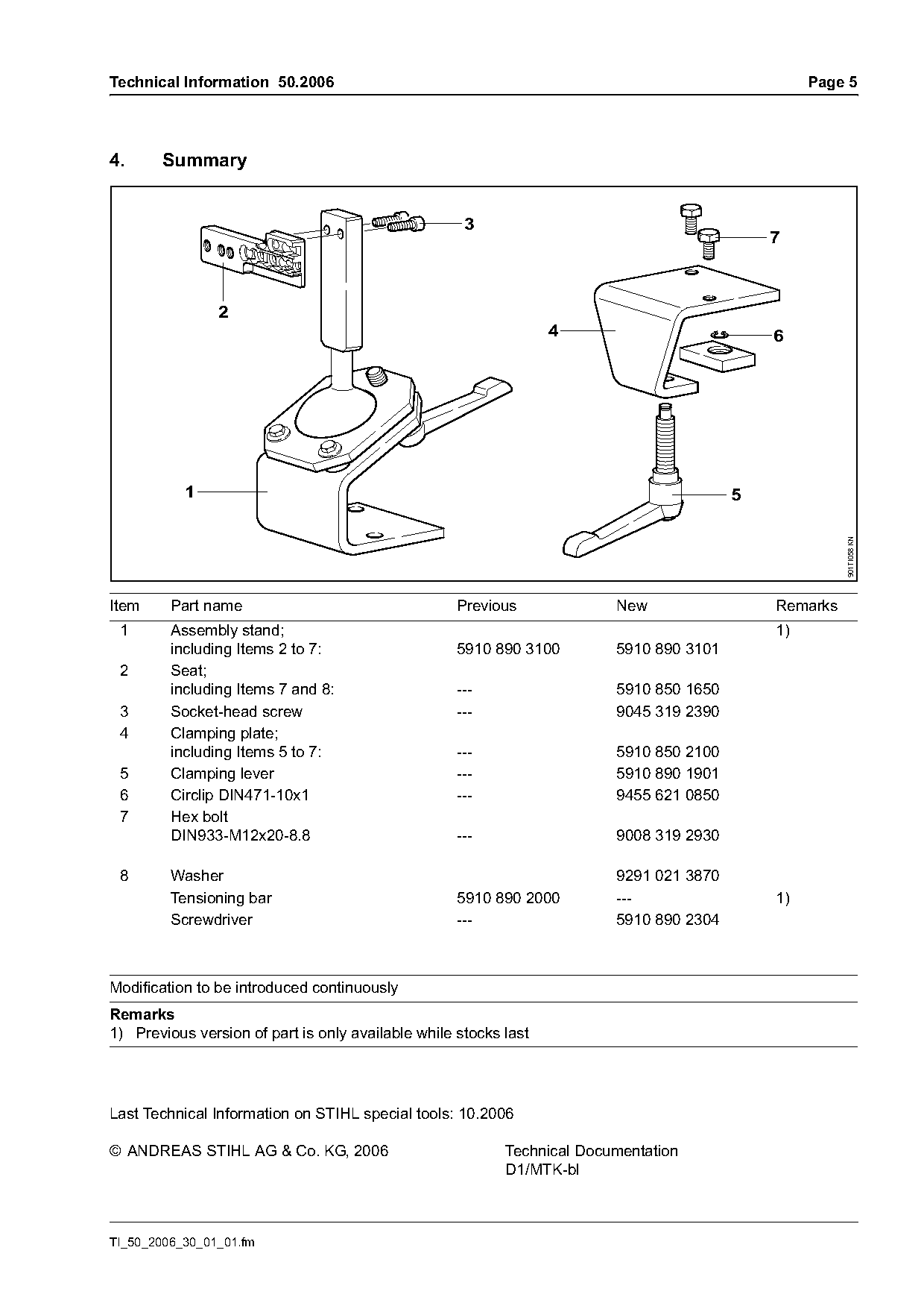
4.     Summary

                                                     3
                                                                                             7

                2
                                                                  4                          6

           1                                                                             5

                                                                                                       901TI058 KN
Item     Part name                                  Previous             New                 Remarks
 1       Assembly stand;                                                                     1)
         including Items 2 to 7:                    5910 890 3100        5910 890 3101
 2       Seat;
         including Items 7 and 8:                   ---                  5910 850 1650
 3       Socket-head screw                          ---                  9045 319 2390
 4       Clamping plate;
         including Items 5 to 7:                    ---                  5910 850 2100
 5       Clamping lever                             ---                  5910 890 1901
 6       Circlip DIN471-10x1                        ---                  9455 621 0850
 7       Hex bolt
         DIN933-M12x20-8.8                          ---                  9008 319 2930

 8       Washer                                                          9291 021 3870
         Tensioning bar                             5910 890 2000        ---                 1)
         Screwdriver                                ---                  5910 890 2304

Modification to be introduced continuously
Remarks
1) Previous version of part is only available while stocks last

Last Technical Information on STIHL special tools: 10.2006

© ANDREAS STIHL AG & Co. KG, 2006                          Technical Documentation
                                                           D1/MTK-bl

TI_50_2006_30_01_01.fm
Most of these PDFs embed fonts with a shifted character map, so the text above was recovered rather than copied — read it as a faithful but imperfect transcription, and treat the page image above each block as the authority where the two disagree — the figures exist only there, because they are vector drawings that text extraction cannot keep.