Technical Information · issue 61 of 2006
Telescoping drive tube assembly; Servicing
IssueTI 61/2006
Part changes (1)
| Was | Becomes | What the bulletin says |
|---|---|---|
| 4138 710 7103 | 4182 710 7107 | Drive tube assembly 4138 710 7103 is now replaced by version 4182 710 7107, which was . |
Full text
Page 1 of 3
Text of page 1 — search, copy, screen readers
STIH)

Technical Information                                                                        61.2006

  Pole Pruner STIHL HT 101 – Series 4182

  Contents
  1. Telescoping drive tube assembly
  2. Servicing

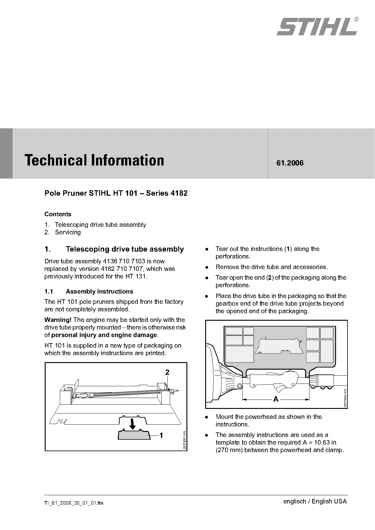
  1.      Telescoping drive tube assembly                          .   Tear out the instructions (1) along the
                                                                       perforations.
  Drive tube assembly 4138 710 7103 is now
  replaced by version 4182 710 7107, which was                     .   Remove the drive tube and accessories.
  previously introduced for the HT 131.                            .   Tear open the end (2) of the packaging along the
                                                                       perforations.
  1.1     Assembly instructions
                                                                   .   Place the drive tube in the packaging so that the
  The HT 101 pole pruners shipped from the factory                     gearbox end of the drive tube projects beyond
  are not completely assembled.                                        the opened end of the packaging.
  Warning! The engine may be started only with the
  drive tube properly mounted – there is otherwise risk
  of personal injury and engine damage.
  HT 101 is supplied in a new type of packaging on
  which the assembly instructions are printed.

                                                2
                                                                                                                      263TI002 KN


                                                                   .   Mount the powerhead as shown in the
                                                                       instructions.
                                                     263TI001 KN

                                            1                      .   The assembly instructions are used as a
                                                                       template to obtain the required A = 10.63 in
                                                                       (270 mm) between the powerhead and clamp.

  TI_61_2006_30_01_01.fm                                                                        englisch / English USA
Page 2 of 3
Text of page 2 — search, copy, screen readers
Page 2                                                                                     Technical Information 61.2006

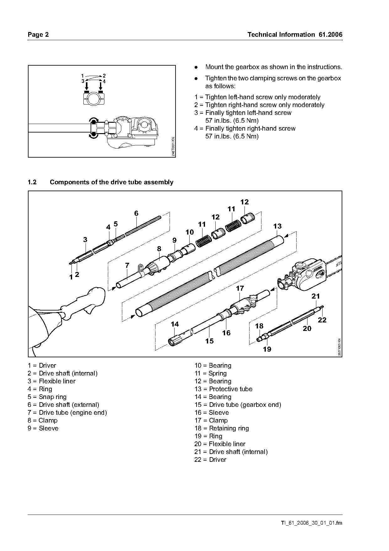
                                                                  .    Mount the gearbox as shown in the instructions.
                   1     2
                   3     4
                                                                  .    Tighten the two clamping screws on the gearbox
                                                                       as follows:
                                                                  1 = Tighten left-hand screw only moderately
                                                                  2 = Tighten right-hand screw only moderately
                                                                  3 = Finally tighten left-hand screw
                                                                      57 in.lbs. (6.5 Nm)
                                                                  4 = Finally tighten right-hand screw
                                                                      57 in.lbs. (6.5 Nm)

                                               246TI001 KN

1.2      Components of the drive tube assembly

                                                                                       12
                                                                                 11
                                       6
                                                                           12
                             4 5                                      11                            13
                                                             10
                   3                             9
                                           8

                                   7
              12
                                                                                      17
                                                                                                                 21

                                                                                                                  22
                                               14                                            18             20
                                                                                16
                                                                       15                                                263TI003 KN


1 = Driver                                                        10 = Bearing
2 = Drive shaft (internal)                                        11 = Spring
3 = Flexible liner                                                12 = Bearing
4 = Ring                                                          13 = Protective tube
5 = Snap ring                                                     14 = Bearing
6 = Drive shaft (external)                                        15 = Drive tube (gearbox end)
7 = Drive tube (engine end)                                       16 = Sleeve
8 = Clamp                                                         17 = Clamp
9 = Sleeve                                                        18 = Retaining ring
                                                                  19 = Ring
                                                                  20 = Flexible liner
                                                                  21 = Drive shaft (internal)
                                                                  22 = Driver

                                                                                                     TI_61_2006_30_01_01.fm
Page 3 of 3
Text of page 3 — search, copy, screen readers
Technical Information 61.2006                                                                          Page 3

2.      Servicing
For servicing and repair of the drive tube assembly,
see TI 32.2006.
Features
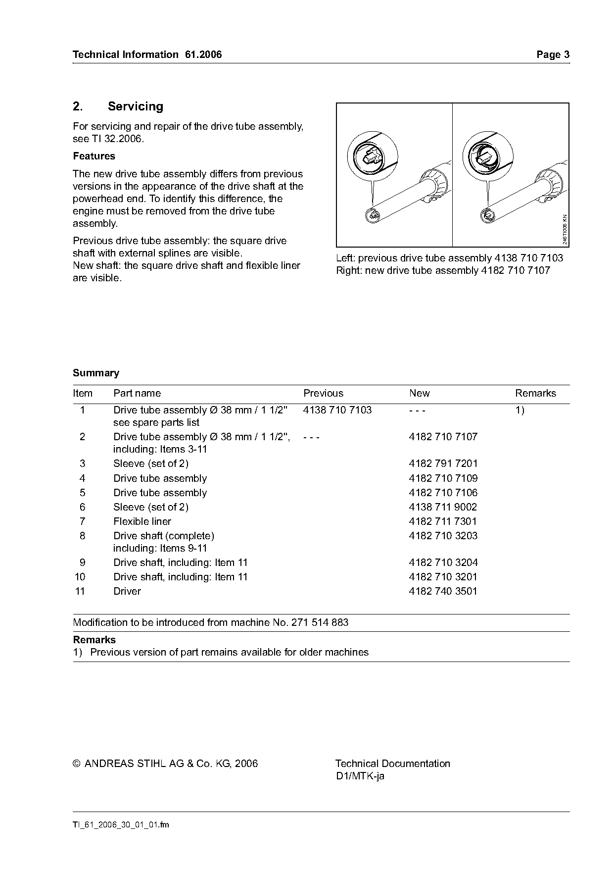
The new drive tube assembly differs from previous
versions in the appearance of the drive shaft at the
powerhead end. To identify this difference, the
engine must be removed from the drive tube

                                                                                                            246TI006 KN
assembly.
Previous drive tube assembly: the square drive
shaft with external splines are visible.                     Left: previous drive tube assembly 4138 710 7103
New shaft: the square drive shaft and flexible liner         Right: new drive tube assembly 4182 710 7107
are visible.

Summary

Item     Part name                                     Previous             New                   Remarks
 1       Drive tube assembly Ø 38 mm / 1 1/2''         4138 710 7103        ---                   1)
         see spare parts list
 2       Drive tube assembly Ø 38 mm / 1 1/2'',        ---                  4182 710 7107
         including: Items 3-11
 3       Sleeve (set of 2)                                                  4182 791 7201
 4       Drive tube assembly                                                4182 710 7109
 5       Drive tube assembly                                                4182 710 7106
 6       Sleeve (set of 2)                                                  4138 711 9002
 7       Flexible liner                                                     4182 711 7301
 8       Drive shaft (complete)                                             4182 710 3203
         including: Items 9-11
 9       Drive shaft, including: Item 11                                    4182 710 3204
10       Drive shaft, including: Item 11                                    4182 710 3201
11       Driver                                                             4182 740 3501

Modification to be introduced from machine No. 271 514 883
Remarks
1) Previous version of part remains available for older machines

© ANDREAS STIHL AG & Co. KG, 2006                            Technical Documentation
                                                             D1/MTK-ja

TI_61_2006_30_01_01.fm
Most of these PDFs embed fonts with a shifted character map, so the text above was recovered rather than copied — read it as a faithful but imperfect transcription, and treat the page image above each block as the authority where the two disagree — the figures exist only there, because they are vector drawings that text extraction cannot keep.