Technical Information · issue 2 of 2007
New STIHL FS 310 Clearing Saw
IssueTI 2/2007
Full text
Page 1 of 10
Text of page 1 — search, copy, screen readers
STIH)

Technical Information                                    02.2007

  New STIHL FS 310 Clearing Saw – Series 4180

  Contents
  1.   Technical Description
  2.   Specifications
  3.   Cutting Tools
  4.   Accessories
  5.   Service Accessories
  6.   Service Note
  7.   Spare Parts

  1.      Technical Description
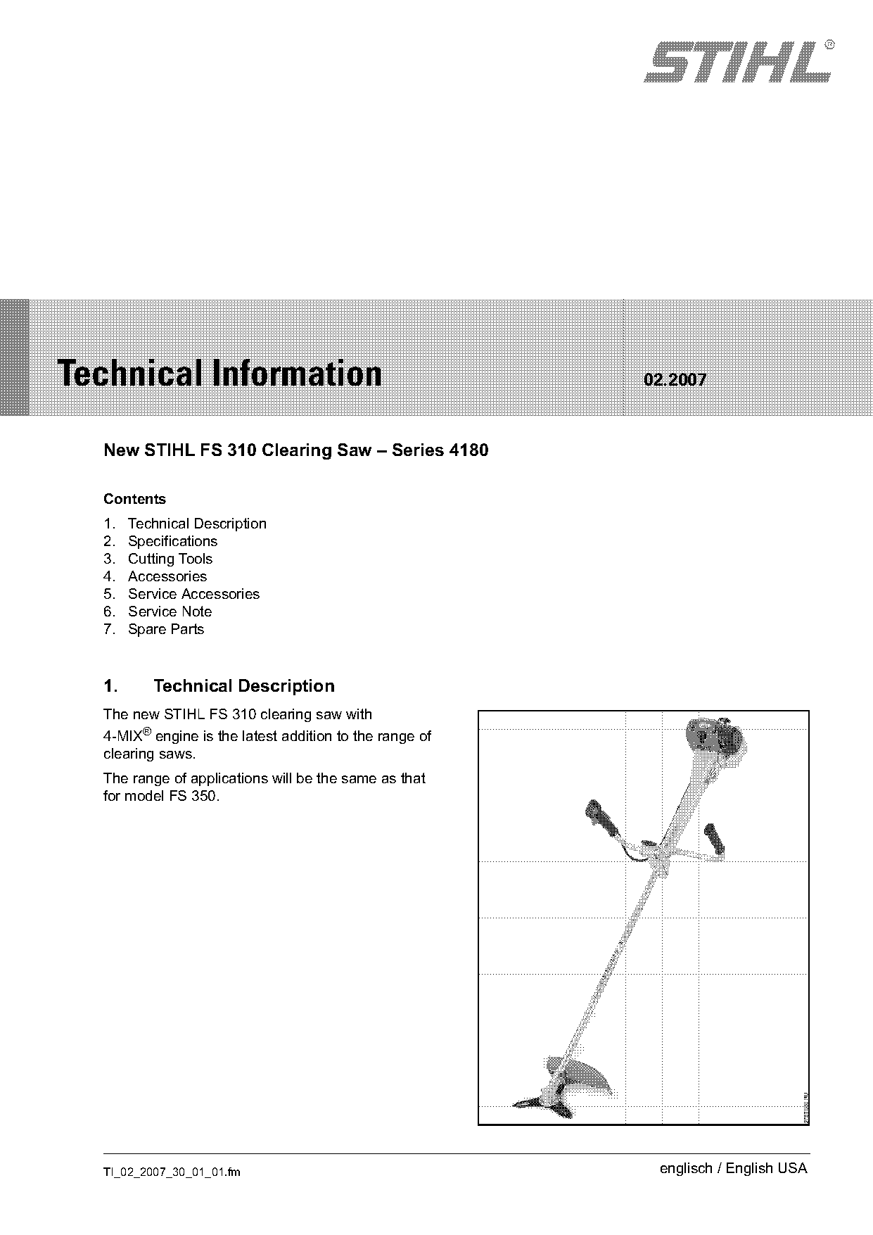
  The new STIHL FS 310 clearing saw with
  4-MIX® engine is the latest addition to the range of
  clearing saws.
  The range of applications will be the same as that
  for model FS 350.

  TI_02_2007_30_01_01.fm                                  englisch / English USA
Page 2 of 10
Text of page 2 — search, copy, screen readers
Page 2                                                                              Technical Information 02.2007

1.1      STIHL 4-MIX® Engine
The 4-MIX® incorporates a patented STIHL
lubrication system. Engine lubrication is provided by
the fuel mixture of gasoline and engine oil.
Compared to a conventional four-stroke gasoline
engine, the 4-MIX® engine has no separate oil
supply in the crankcase.
The STIHL 4-MIX® engine uses the same 50:1
fuel/oil mixture as all other STIHL two-stroke

                                                                                                                         273TI003 KN
engines.
The benefits of this new concept are:
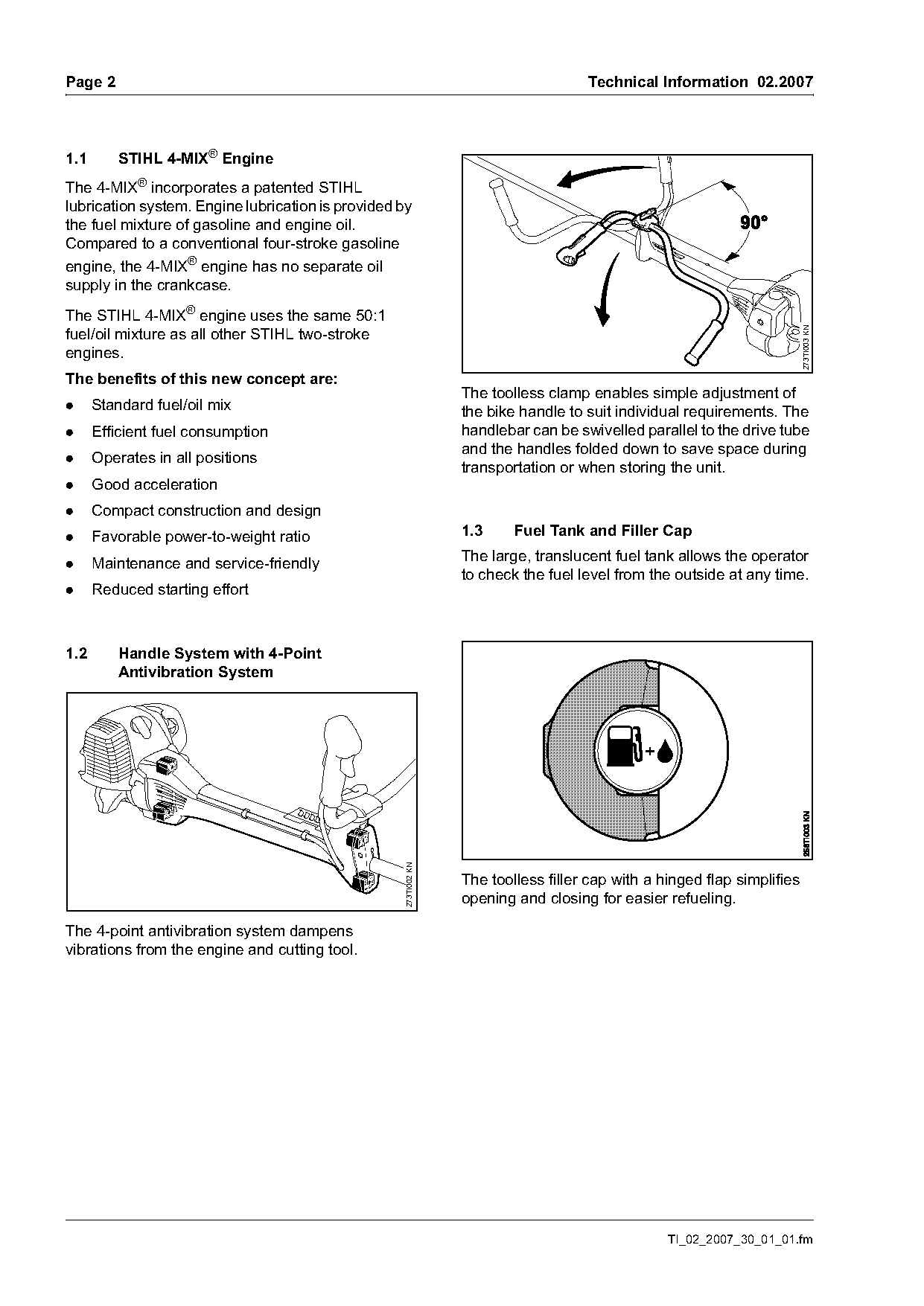
                                                                 The toolless clamp enables simple adjustment of
.     Standard fuel/oil mix                                      the bike handle to suit individual requirements. The
.     Efficient fuel consumption                                 handlebar can be swivelled parallel to the drive tube
                                                                 and the handles folded down to save space during
.     Operates in all positions
                                                                 transportation or when storing the unit.
.     Good acceleration
.     Compact construction and design
.     Favorable power-to-weight ratio                            1.3     Fuel Tank and Filler Cap

.     Maintenance and service-friendly                           The large, translucent fuel tank allows the operator
                                                                 to check the fuel level from the outside at any time.
.     Reduced starting effort

1.2      Handle System with 4-Point
         Antivibration System
                                                   273TI002 KN

                                                                 The toolless filler cap with a hinged flap simplifies
                                                                 opening and closing for easier refueling.

The 4-point antivibration system dampens
vibrations from the engine and cutting tool.

                                                                                                 TI_02_2007_30_01_01.fm
Page 3 of 10
Text of page 3 — search, copy, screen readers
Technical Information 02.2007                                                                        Page 3

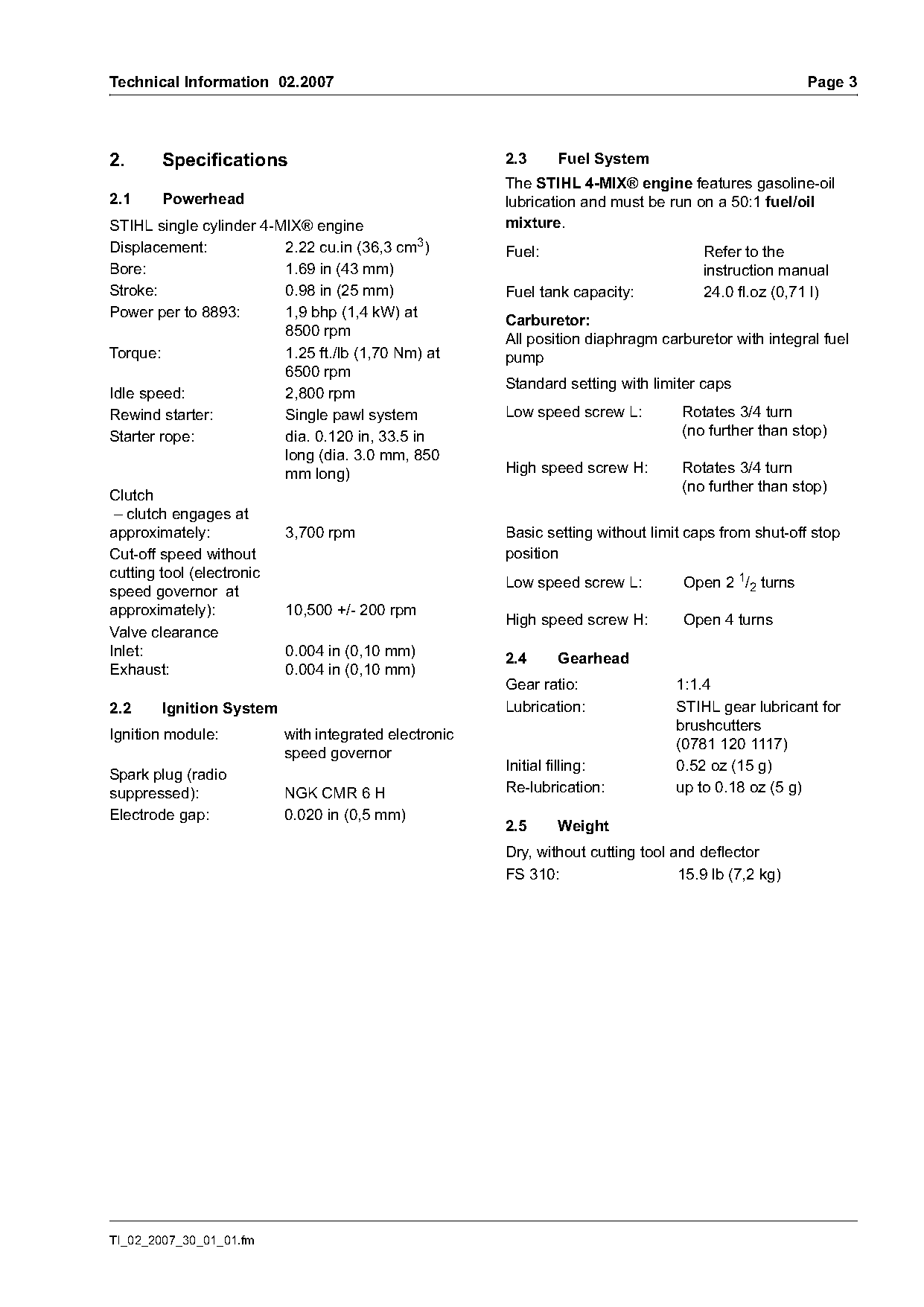
2.     Specifications                                  2.3     Fuel System
                                                       The STIHL 4-MIX® engine features gasoline-oil
2.1     Powerhead                                      lubrication and must be run on a 50:1 fuel/oil
STIHL single cylinder 4-MIX® engine                    mixture.
Displacement:            2.22 cu.in (36,3 cm3)         Fuel:                         Refer to the
Bore:                    1.69 in (43 mm)                                             instruction manual
Stroke:                  0.98 in (25 mm)               Fuel tank capacity:           24.0 fl.oz (0,71 l)
Power per to 8893:       1,9 bhp (1,4 kW) at
                                                       Carburetor:
                         8500 rpm
                                                       All position diaphragm carburetor with integral fuel
Torque:                  1.25 ft./lb (1,70 Nm) at      pump
                         6500 rpm
                                                       Standard setting with limiter caps
Idle speed:              2,800 rpm
Rewind starter:          Single pawl system            Low speed screw L:         Rotates 3/4 turn
Starter rope:            dia. 0.120 in, 33.5 in                                   (no further than stop)
                         long (dia. 3.0 mm, 850
                         mm long)                      High speed screw H:        Rotates 3/4 turn
                                                                                  (no further than stop)
Clutch
 – clutch engages at
approximately:           3,700 rpm                     Basic setting without limit caps from shut-off stop
Cut-off speed without                                  position
cutting tool (electronic
                                                       Low speed screw L:         Open 2 1/2 turns
speed governor at
approximately):          10,500 +/- 200 rpm
                                                       High speed screw H:        Open 4 turns
Valve clearance
Inlet:                   0.004 in (0,10 mm)            2.4     Gearhead
Exhaust:                 0.004 in (0,10 mm)
                                                       Gear ratio:               1:1.4
2.2     Ignition System                                Lubrication:              STIHL gear lubricant for
                                                                                 brushcutters
Ignition module:          with integrated electronic
                                                                                 (0781 120 1117)
                          speed governor
                                                       Initial filling:          0.52 oz (15 g)
Spark plug (radio
suppressed):              NGK CMR 6 H                  Re-lubrication:           up to 0.18 oz (5 g)
Electrode gap:            0.020 in (0,5 mm)
                                                       2.5     Weight
                                                       Dry, without cutting tool and deflector
                                                       FS 310:                    15.9 lb (7,2 kg)

TI_02_2007_30_01_01.fm
Page 4 of 10
Text of page 4 — search, copy, screen readers
Page 4                                                                Technical Information 02.2007

3.       Cutting Tools
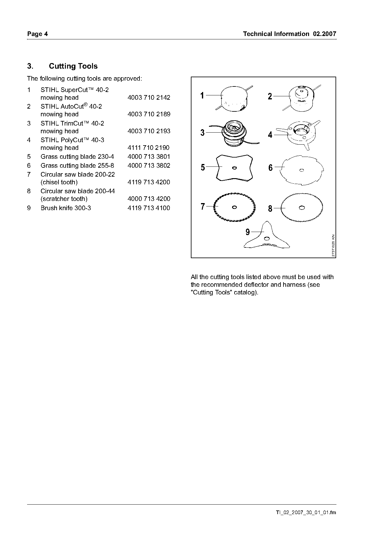
The following cutting tools are approved:
1    STIHL SuperCut™ 40-2
     mowing head                   4003 710 2142      1                       2
2    STIHL AutoCut® 40-2
     mowing head                   4003 710 2189
3    STIHL TrimCut™ 40-2
     mowing head                   4003 710 2193      3
4    STIHL PolyCut™ 40-3
                                                                               4
     mowing head                   4111 710 2190
5    Grass cutting blade 230-4     4000 713 3801
6    Grass cutting blade 255-8     4000 713 3802      5                        6
7    Circular saw blade 200-22
     (chisel tooth)                4119 713 4200
8    Circular saw blade 200-44
     (scratcher tooth)             4000 713 4200
9    Brush knife 300-3             4119 713 4100      7                        8


                                                                                                       273TI020 KN
                                                   All the cutting tools listed above must be used with
                                                   the recommended deflector and harness (see
                                                   "Cutting Tools" catalog).

                                                                                   TI_02_2007_30_01_01.fm
Page 5 of 10
Text of page 5 — search, copy, screen readers
Technical Information 02.2007                                                                         Page 5

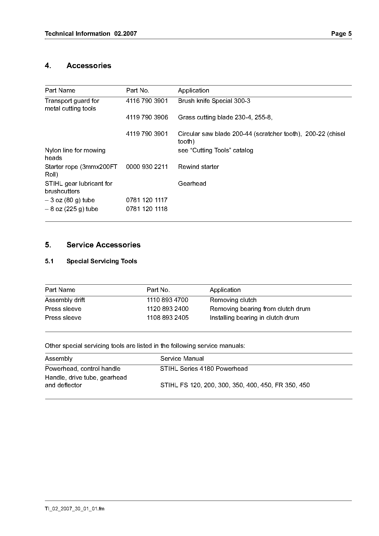
4.      Accessories

Part Name                    Part No.            Application
Transport guard for          4116 790 3901       Brush knife Special 300-3
metal cutting tools
                             4119 790 3906       Grass cutting blade 230-4, 255-8,

                             4119 790 3901       Circular saw blade 200-44 (scratcher tooth), 200-22 (chisel
                                                 tooth)
Nylon line for mowing                            see “Cutting Tools” catalog
heads
Starter rope (3mmx200FT      0000 930 2211       Rewind starter
Roll)
STIHL gear lubricant for                         Gearhead
brushcutters
– 3 oz (80 g) tube           0781 120 1117
– 8 oz (225 g) tube          0781 120 1118

5.      Service Accessories

5.1     Special Servicing Tools

Part Name                            Part No.                  Application
Assembly drift                       1110 893 4700             Removing clutch
Press sleeve                         1120 893 2400             Removing bearing from clutch drum
Press sleeve                         1108 893 2405             Installing bearing in clutch drum

Other special servicing tools are listed in the following service manuals:

Assembly                                  Service Manual
Powerhead, control handle                 STIHL Series 4180 Powerhead
Handle, drive tube, gearhead
and deflector                             STIHL FS 120, 200, 300, 350, 400, 450, FR 350, 450

TI_02_2007_30_01_01.fm
Page 6 of 10
Text of page 6 — search, copy, screen readers
Page 6                                                                             Technical Information 02.2007

5.2      Servicing Aids

Part Name                            Part No.                    Application
Valve clearance adjusting kit        4180 007 1005               Checking, adjusting valve clearance
Set of gaskets                       4180 007 1015               Engine
Carburetor parts kit                 4180 007 1061               Carburetor
Lubricating grease
(8 oz (225 g) tube)                  0781 120 1111               Oil seals
Press fluid (100 ml bottle)          0781 957 9000               Rubber elements of AV system
Dirko HT sealant, red                0783 830 2000               Sealing engine pan/cylinder, cylinder/cam gear
(3.2 oz (90 g) tube)                                             cover
Standard commercial, solvent-                                    Cleaning crankshaft
based degreaser                                                  (see TI 25.2005)

6.       Service Note
If the machine is to be operated during repair
please refer to the unit instruction manual
regarding proper safety and operation.

6.1      Servicing Antivibration System

6.1.1    Removing
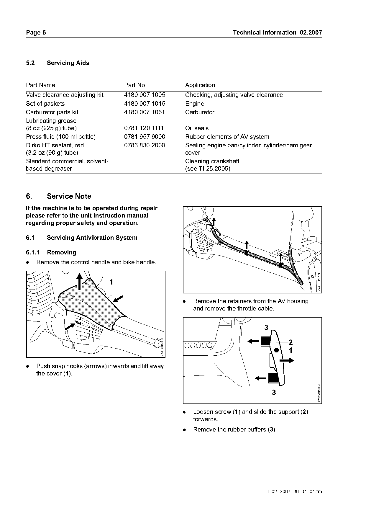
.     Remove the control handle and bike handle.

                                                                                                                   273TI018 KN
                                1

                                                                 .   Remove the retainers from the AV housing
                                                                     and remove the throttle cable.


                                                                                                        2
                                                   273TI005 KN


.     Push snap hooks (arrows) inwards and lift away
      the cover (1).
                                                                                                                    273TI006 KN


                                                                 .   Loosen screw (1) and slide the support (2)
                                                                     forwards.
                                                                 .   Remove the rubber buffers (3).

                                                                                               TI_02_2007_30_01_01.fm
Page 7 of 10
Text of page 7 — search, copy, screen readers
Technical Information 02.2007                                                                                      Page 7

                                                                                          1
                                                                                                  b
                                                                                      a

                                                                                          a
                                                                                                      b

                                                                                                                         273TI009 KN
                                                    273TI007 KN
                                                                                              1

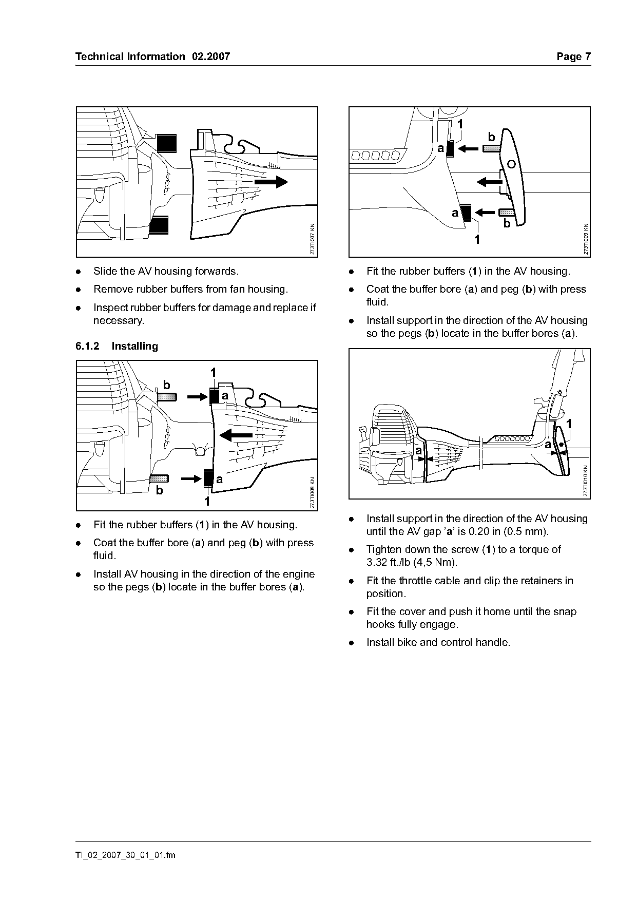
.   Slide the AV housing forwards.                                .   Fit the rubber buffers (1) in the AV housing.
.   Remove rubber buffers from fan housing.                       .   Coat the buffer bore (a) and peg (b) with press
                                                                      fluid.
.   Inspect rubber buffers for damage and replace if
    necessary.                                                    .   Install support in the direction of the AV housing
                                                                      so the pegs (b) locate in the buffer bores (a).
6.1.2   Installing

                             1
                     b
                                 a


                                                                                 a                             a

                                                                                                                         273TI010 KN
                                a
                                                    273TI008 KN

                 b
                            1
                                                                  .   Install support in the direction of the AV housing
.   Fit the rubber buffers (1) in the AV housing.
                                                                      until the AV gap ’a’ is 0.20 in (0.5 mm).
.   Coat the buffer bore (a) and peg (b) with press
                                                                  .   Tighten down the screw (1) to a torque of
    fluid.
                                                                      3.32 ft./lb (4,5 Nm).
.   Install AV housing in the direction of the engine
                                                                  .   Fit the throttle cable and clip the retainers in
    so the pegs (b) locate in the buffer bores (a).
                                                                      position.
                                                                  .   Fit the cover and push it home until the snap
                                                                      hooks fully engage.
                                                                  .   Install bike and control handle.

TI_02_2007_30_01_01.fm
Page 8 of 10
Text of page 8 — search, copy, screen readers
Page 8                                                                                  Technical Information 02.2007

6.2      Servicing the Clutch Drum and Bearing

6.2.1    Removing
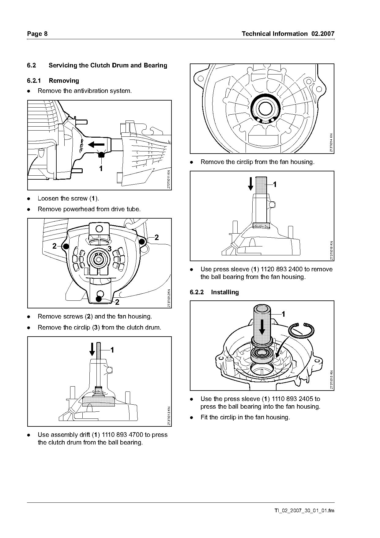
.     Remove the antivibration system.

                                                                                                                       273TI014 KN
                                                                   .   Remove the circlip from the fan housing.
                           1                         273TI011 KN

                                                                                                   1
.     Loosen the screw (1).
.     Remove powerhead from drive tube.


                                                                                                                        273TI019 KN
           2                   3

                                                                   .   Use press sleeve (1) 1120 893 2400 to remove
                                                                       the ball bearing from the fan housing.

                                                                   6.2.2   Installing
                                                     273TI012KN

                                   2
.     Remove screws (2) and the fan housing.                                                           1
.     Remove the circlip (3) from the clutch drum.

                               1
                                                                                                                        273TI015 KN

                                                                   .   Use the press sleeve (1) 1110 893 2405 to
                                                                       press the ball bearing into the fan housing.
                                                     273TI013 KN

                                                                   .   Fit the circlip in the fan housing.

.     Use assembly drift (1) 1110 893 4700 to press
      the clutch drum from the ball bearing.

                                                                                                   TI_02_2007_30_01_01.fm
Page 9 of 10
Text of page 9 — search, copy, screen readers
Technical Information 02.2007                                                                                 Page 9

                                                                 6.3    Checking Valve Clearance
                                   1                             Check valve clearance after the first 139 hours of
                                                                 operation and adjust if necessary. Check and adjust
                                                                 valve clearance only when the engine is cold, using
                                                                 the “Valve clearance adjusting kit“ 4180 007 1005,
                                                                 consisting of feeler gauge, sealing ring and gasket.

                                                                 6.4    Leakage Test

                                                   273TI016 KN
                                                                 Defective oil, and gaskets or cracks in castings may
                                                                 allow extra air to enter the engine and lean out the
                                                                 fuel, oil and air mixture.
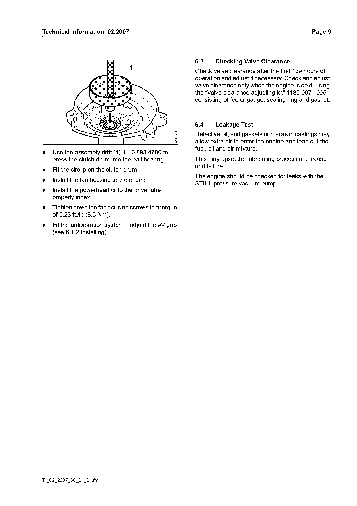
.   Use the assembly drift (1) 1110 893 4700 to
    press the clutch drum into the ball bearing.                 This may upset the lubricating process and cause
                                                                 unit failure.
.   Fit the circlip on the clutch drum.
                                                                 The engine should be checked for leaks with the
.   Install the fan housing to the engine.
                                                                 STIHL pressure vacuum pump.
.   Install the powerhead onto the drive tube
    properly index.
.   Tighten down the fan housing screws to a torque
    of 6.23 ft./lb (8,5 Nm).
.   Fit the antivibration system – adjust the AV gap
    (see 6.1.2 Installing).

TI_02_2007_30_01_01.fm
Page 10 of 10
Text of page 10 — search, copy, screen readers
Page 10                                                                              Technical Information 02.2007

6.5    Service Note and Tightening Torques                      .
The following service manuals are available for                         Reparaturvorgang                       FS 310
servicing procedures and tightening torques:                        1   Replace short block.                   50
                                                                    2   Replace crankcase, crankcase
Assembly                  Service Manual
                                                                        gasket or re-seal crankcase. Includes
Powerhead, control        STIHL Series 4180                             air leak test.                         100
handle                    Powerhead                                 3   Replace crankshaft main bearing(s).
Handle, drive tube,       STIHL FS 120, 200, 300,                       Includes air leak test.                100
gearhead and deflector    350, 400, 450,                            4   Replace crankshaft seal(s). Includes
                          FR 350, 450                                   air leak test.                         70
                                                                    5   Perform engine air leak test.          25
6.6    Repair Times
                                                                    6   Replace cylinder and/or piston.
The specified repair times assume that the work is                      Includes air leak test and repair of
performed by trained personnel in a properly                            components causing failure.            100
equipped service workshop.                                          7   Replace ignition module or flywheel.
Repair times are quoted in minutes.                                     Includes stop circuit test.            25
This table for the FS 310 can be added to the STIHL                 8   Replace fuel tank line, tank vent, or
repair times table.                                                     fuel pick-up body.                     15
                                                                    9   Replace intake manifold or intake
6.7    Serial Number                                                    flange.                                20
                                                                10      Repair or replace carburetor.
                                                                        Includes fuel system testing.          30
                                                                11      Repair throttle control                25
                                                                12      Repair or replace rewind starter       15
                                                                13      Repair or replace clutch, clutch shoes
                                                                        or clutch springs                      30
                                                                14      Replace muffler                        15
                                                                15      Replace air filter or filter housing   15
                                                                16      Repair or replace stop switch.
                                                  273TI017 KN

                                                                        Includes circuit testing               20
                                                                17      Replace clutch housing.                20
                                                                18      Replace drive shaft and/or drive tube. 20
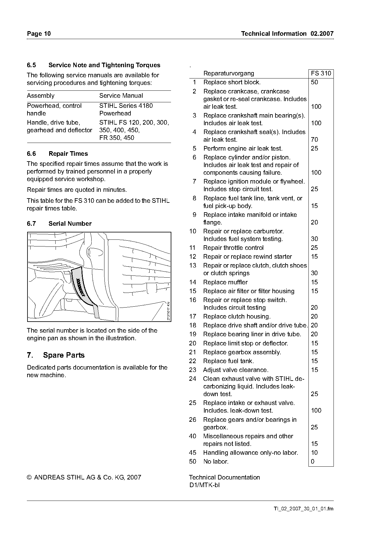
The serial number is located on the side of the
                                                                19      Replace bearing liner in drive tube. 20
engine pan as shown in the illustration.
                                                                20      Replace limit stop or deflector.       15
                                                                21      Replace gearbox assembly.              15
7.    Spare Parts
                                                                22      Replace fuel tank.                     15
Dedicated parts documentation is available for the              23      Adjust valve clearance.                15
new machine.
                                                                24      Clean exhaust valve with STIHL de-
                                                                        carbonizing liquid. Includes leak-
                                                                        down test.                             25
                                                                25      Replace intake or exhaust valve.
                                                                        Includes. leak-down test.              100
                                                                26      Replace gears and/or bearings in
                                                                        gearbox.                               25
                                                                40      Miscellaneous repairs and other
                                                                        repairs not listed.                    15
                                                                45      Handling allowance only-no labor.      10
                                                                50      No labor.                              0

© ANDREAS STIHL AG & Co. KG, 2007                               Technical Documentation
                                                                D1/MTK-bl

                                                                                                TI_02_2007_30_01_01.fm
Most of these PDFs embed fonts with a shifted character map, so the text above was recovered rather than copied — read it as a faithful but imperfect transcription, and treat the page image above each block as the authority where the two disagree — the figures exist only there, because they are vector drawings that text extraction cannot keep.