Technical Information · issue 7 of 2007
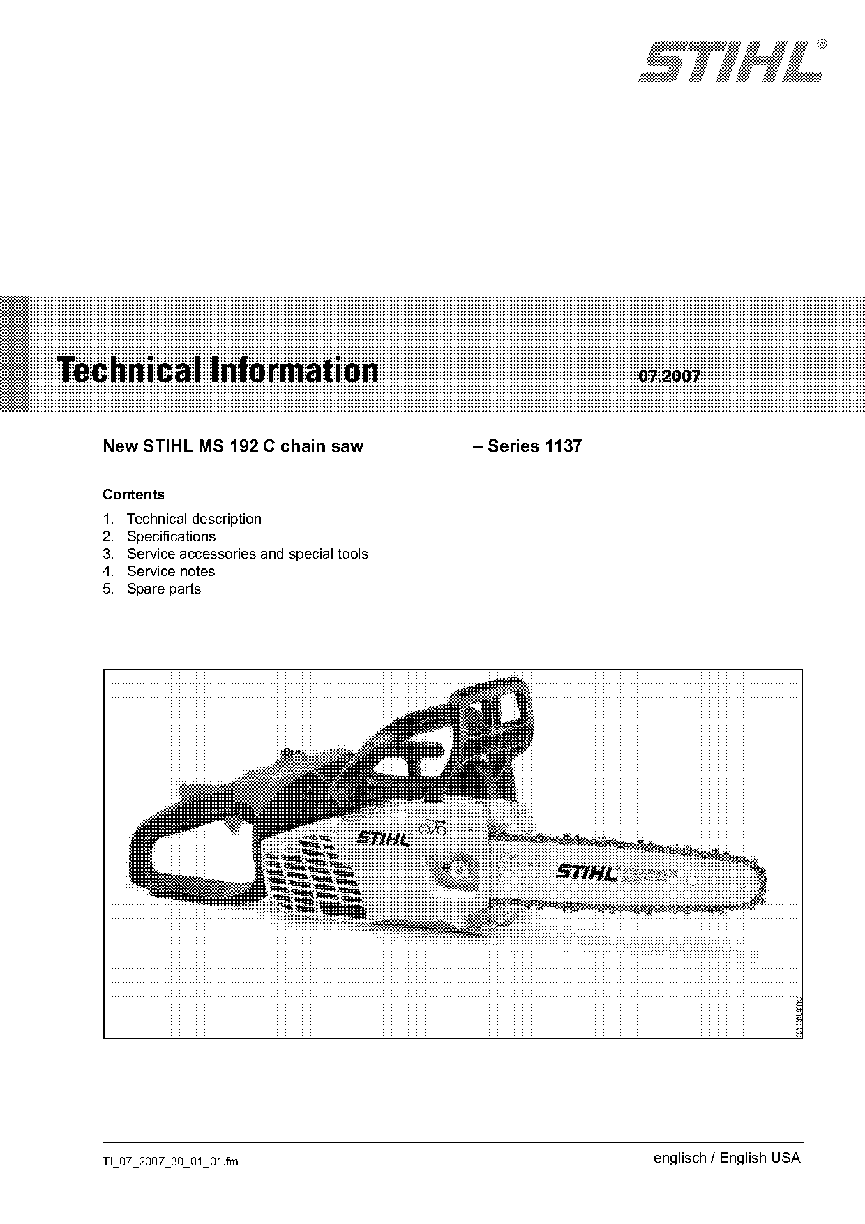
New STIHL MS 192 C chain saw
IssueTI 7/2007
Engine family 1137
Full text
Page 1 of 10
Text of page 1 — search, copy, screen readers
STIH)

Technical Information                                          07.2007

  New STIHL MS 192 C chain saw                 – Series 1137

  Contents
  1.   Technical description
  2.   Specifications
  3.   Service accessories and special tools
  4.   Service notes
  5.   Spare parts

  TI_07_2007_30_01_01.fm                                        englisch / English USA
Page 2 of 10
Text of page 2 — search, copy, screen readers
Page 2                                                                         Technical Information 07.2007

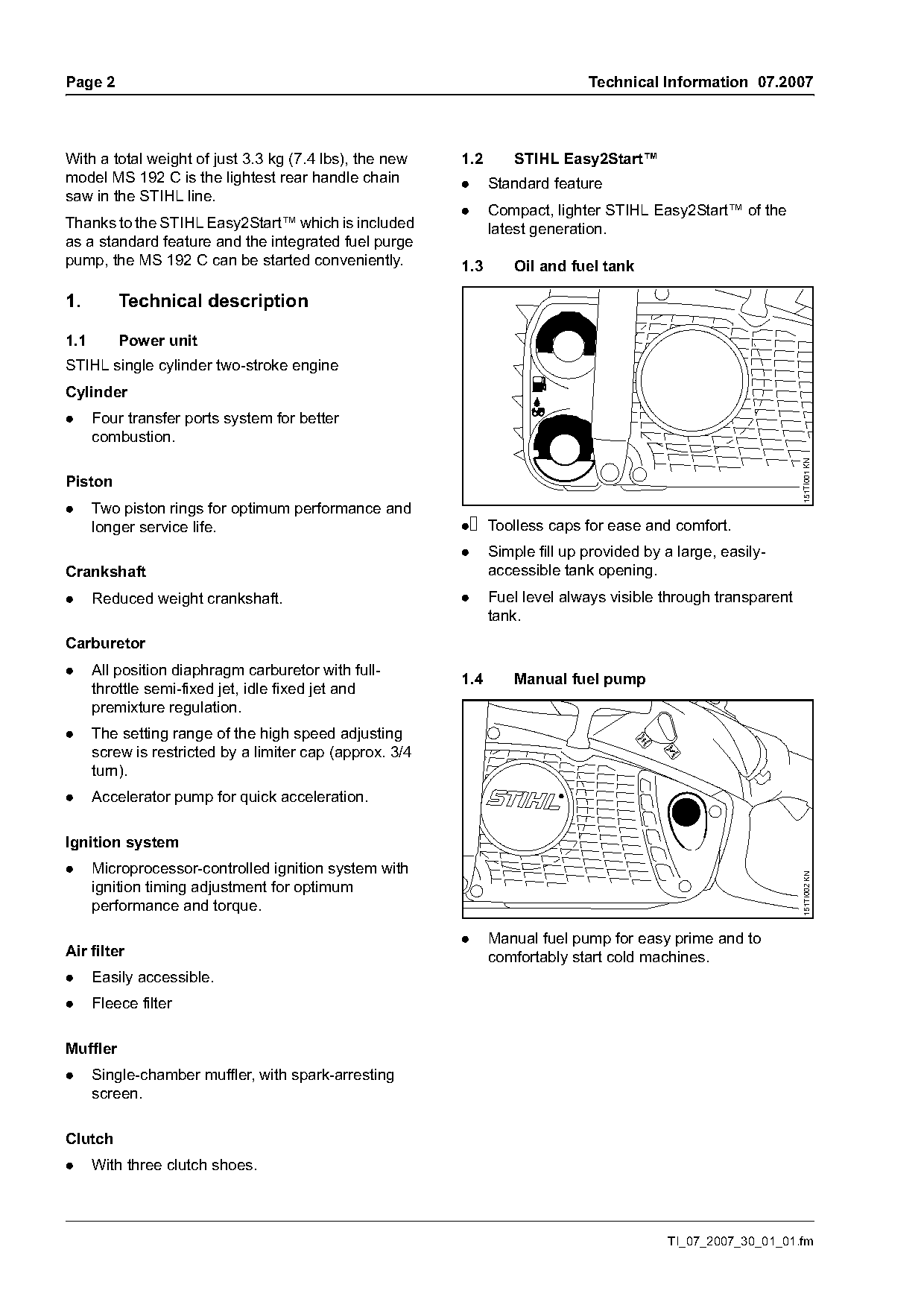
With a total weight of just 3.3 kg (7.4 lbs), the new     1.2       STIHL Easy2Start™
model MS 192 C is the lightest rear handle chain          .     Standard feature
saw in the STIHL line.
                                                          .     Compact, lighter STIHL Easy2Start™ of the
Thanks to the STIHL Easy2Start™ which is included               latest generation.
as a standard feature and the integrated fuel purge
pump, the MS 192 C can be started conveniently.           1.3       Oil and fuel tank

1.        Technical description

1.1       Power unit
STIHL single cylinder two-stroke engine
Cylinder
.     Four transfer ports system for better
      combustion.

                                                                                                                 151TI001 KN
Piston
.     Two piston rings for optimum performance and
      longer service life.                                .     Toolless caps for ease and comfort.
                                                          .     Simple fill up provided by a large, easily-
Crankshaft                                                      accessible tank opening.
.     Reduced weight crankshaft.                          .     Fuel level always visible through transparent
                                                                tank.
Carburetor
.     All position diaphragm carburetor with full-
                                                          1.4       Manual fuel pump
      throttle semi-fixed jet, idle fixed jet and
      premixture regulation.
.     The setting range of the high speed adjusting
      screw is restricted by a limiter cap (approx. 3/4
      turn).
.     Accelerator pump for quick acceleration.

Ignition system
.     Microprocessor-controlled ignition system with
                                                                                                                151TI002 KN

      ignition timing adjustment for optimum
      performance and torque.

                                                          .     Manual fuel pump for easy prime and to
Air filter                                                      comfortably start cold machines.
.     Easily accessible.
.     Fleece filter

Muffler
.     Single-chamber muffler, with spark-arresting
      screen.

Clutch
.     With three clutch shoes.

                                                                                           TI_07_2007_30_01_01.fm
Page 3 of 10
Text of page 3 — search, copy, screen readers
Technical Information 07.2007                                                                       Page 3

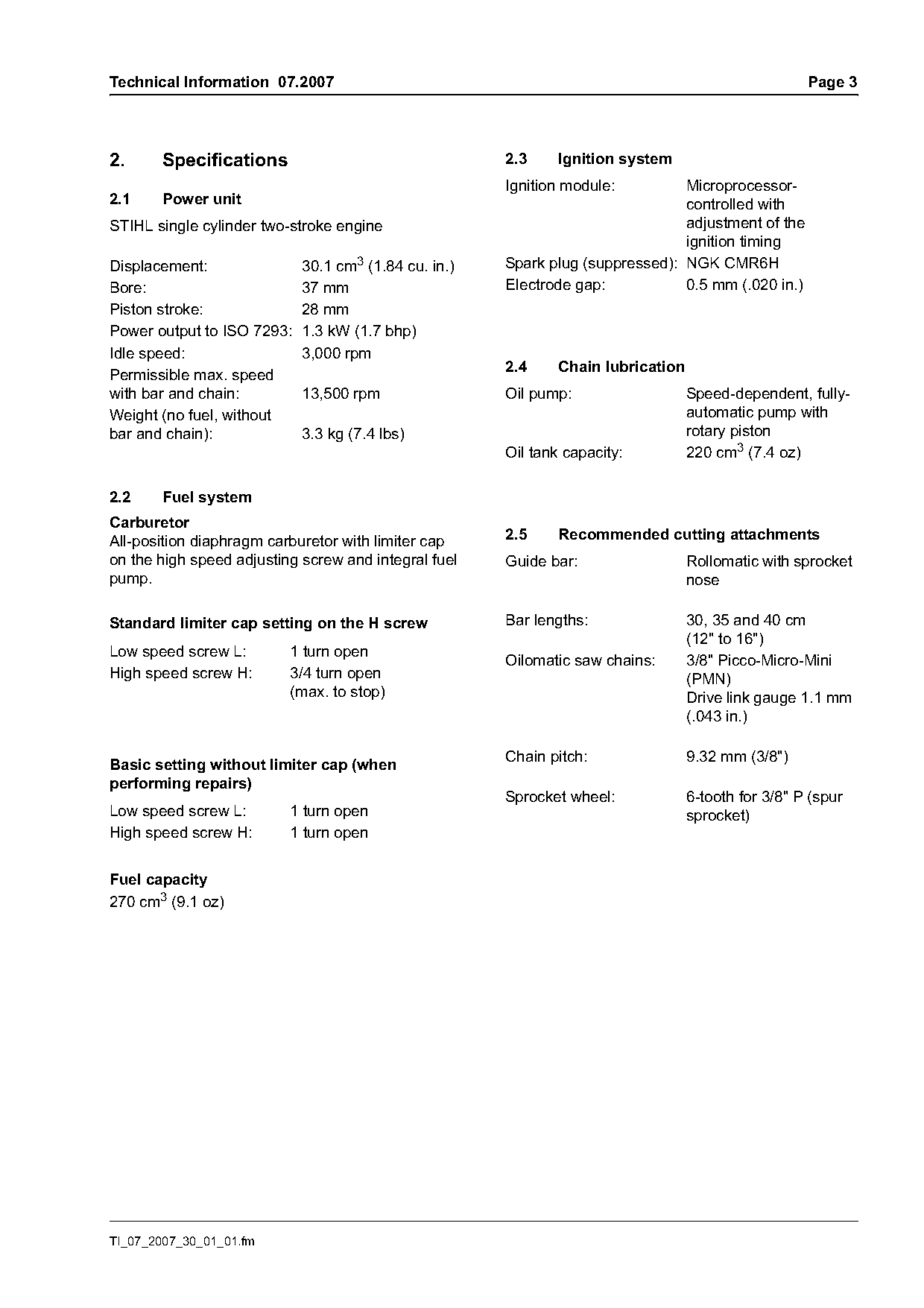
2.     Specifications                                 2.3     Ignition system
                                                      Ignition module:         Microprocessor-
2.1    Power unit                                                              controlled with
STIHL single cylinder two-stroke engine                                        adjustment of the
                                                                               ignition timing
Displacement:             30.1 cm3 (1.84 cu. in.)     Spark plug (suppressed): NGK CMR6H
Bore:                     37 mm                       Electrode gap:           0.5 mm (.020 in.)
Piston stroke:            28 mm
Power output to ISO 7293: 1.3 kW (1.7 bhp)
Idle speed:               3,000 rpm
Permissible max. speed                                2.4     Chain lubrication
with bar and chain:       13,500 rpm                  Oil pump:                   Speed-dependent, fully-
Weight (no fuel, without                                                          automatic pump with
bar and chain):           3.3 kg (7.4 lbs)                                        rotary piston
                                                      Oil tank capacity:          220 cm3 (7.4 oz)

2.2    Fuel system
Carburetor
All-position diaphragm carburetor with limiter cap    2.5     Recommended cutting attachments
on the high speed adjusting screw and integral fuel   Guide bar:                  Rollomatic with sprocket
pump.                                                                             nose

Standard limiter cap setting on the H screw           Bar lengths:                30, 35 and 40 cm
                                                                                  (12" to 16")
Low speed screw L:        1 turn open
                                                      Oilomatic saw chains:       3/8" Picco-Micro-Mini
High speed screw H:       3/4 turn open                                           (PMN)
                          (max. to stop)                                          Drive link gauge 1.1 mm
                                                                                  (.043 in.)

                                                      Chain pitch:                9.32 mm (3/8")
Basic setting without limiter cap (when
performing repairs)
                                                      Sprocket wheel:             6-tooth for 3/8" P (spur
Low speed screw L:        1 turn open                                             sprocket)
High speed screw H:       1 turn open

Fuel capacity
270 cm3 (9.1 oz)

TI_07_2007_30_01_01.fm
Page 4 of 10
Text of page 4 — search, copy, screen readers
Page 4                                                                          Technical Information 07.2007

3.       Service accessories and special
         tools

3.1      Service accessories

Part name                         Part No.          Use
Grease (225 g tube)               0781 120 1111     Oil seals, oil pump drive, sprocket bearings, chain tensioner
                                                    Bearing and sliding surfaces for throttle trigger, brake lever
                                                    and trigger interlock

STIHL special lubricant           0781 417 1315     Bearing bore in rope rotor, rewind spring in fan housing

Standard commercially                               Cleaning crankshaft stub and cone on flywheel
available CFC and HFC-free
solvent-based degreasing
agent

Sealing compound                  0783 830 2000     Engine pan, oil seals (outside diameter)
Dirko HT red sealant

STIHL Press Fluid OH 723          0781 957 9000     Rubber elements

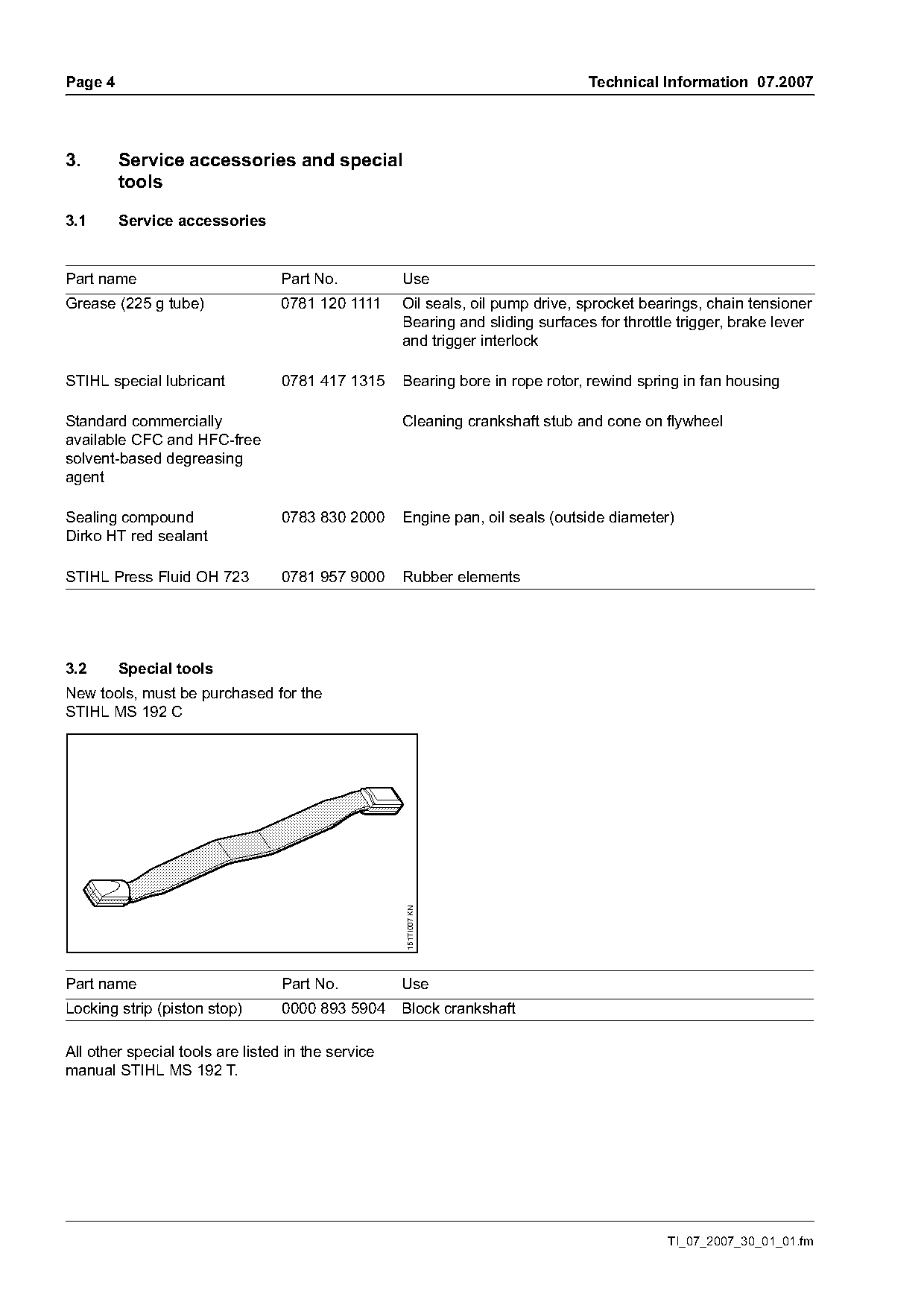
3.2      Special tools
New tools, must be purchased for the
STIHL MS 192 C
                                                    151TI007 KN

Part name                         Part No.          Use
Locking strip (piston stop)       0000 893 5904     Block crankshaft

All other special tools are listed in the service
manual STIHL MS 192 T.

                                                                                            TI_07_2007_30_01_01.fm
Page 5 of 10
Text of page 5 — search, copy, screen readers
Technical Information 07.2007                                                                          Page 5

4.        Service notes                                  4.1.2   Maintenance / repair

4.1       Carburetor adjustment

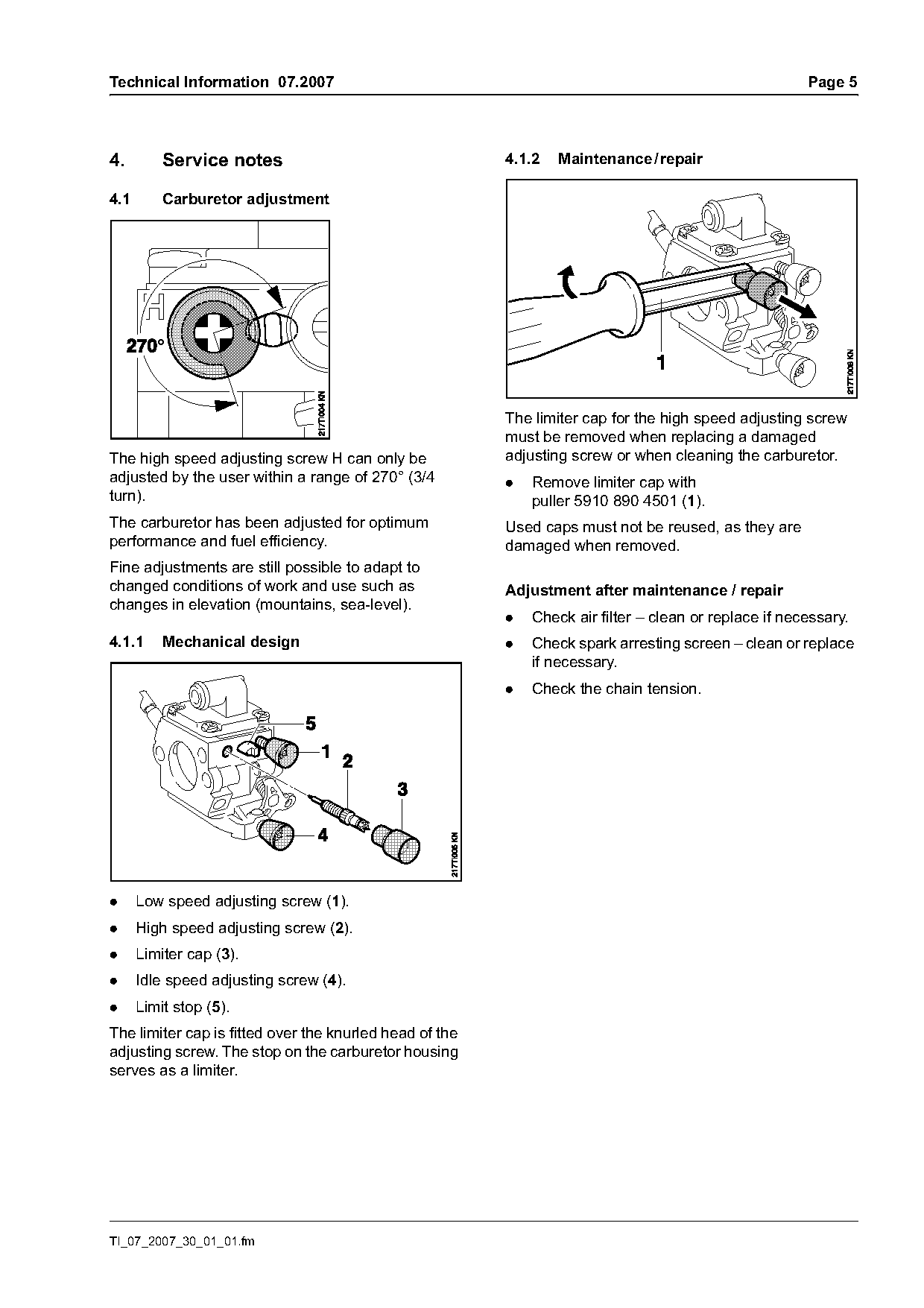
                                                         The limiter cap for the high speed adjusting screw
                                                         must be removed when replacing a damaged
The high speed adjusting screw H can only be             adjusting screw or when cleaning the carburetor.
adjusted by the user within a range of 270° (3/4         .   Remove limiter cap with
turn).                                                       puller 5910 890 4501 (1).
The carburetor has been adjusted for optimum             Used caps must not be reused, as they are
performance and fuel efficiency.                         damaged when removed.
Fine adjustments are still possible to adapt to
changed conditions of work and use such as               Adjustment after maintenance / repair
changes in elevation (mountains, sea-level).
                                                         .   Check air filter – clean or replace if necessary.
4.1.1     Mechanical design                              .   Check spark arresting screen – clean or replace
                                                             if necessary.
                                                         .   Check the chain tension.

.     Low speed adjusting screw (1).
.     High speed adjusting screw (2).
.     Limiter cap (3).
.     Idle speed adjusting screw (4).
.     Limit stop (5).
The limiter cap is fitted over the knurled head of the
adjusting screw. The stop on the carburetor housing
serves as a limiter.

TI_07_2007_30_01_01.fm
Page 6 of 10
Text of page 6 — search, copy, screen readers
Page 6                                                                      Technical Information 07.2007

4.1.3    Basic setting without limiter cap               4.1.4   Securing the limiter cap

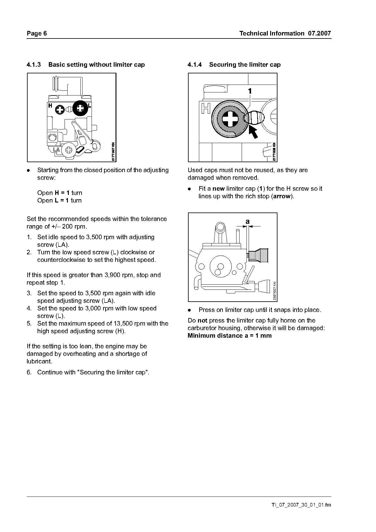
.   Starting from the closed position of the adjusting   Used caps must not be reused, as they are
    screw:                                               damaged when removed.
                                                         .   Fit a new limiter cap (1) for the H screw so it
    Open H = 1 turn                                          lines up with the rich stop (arrow).
    Open L = 1 turn

Set the recommended speeds within the tolerance                                a
range of +/– 200 rpm.
1. Set idle speed to 3,500 rpm with adjusting
   screw (LA).
2. Turn the low speed screw (L) clockwise or
   counterclockwise to set the highest speed.

If this speed is greater than 3,900 rpm, stop and
repeat step 1.
                                                                                         256TI027 KN

3. Set the speed to 3,500 rpm again with idle
   speed adjusting screw (LA).
4. Set the speed to 3,000 rpm with low speed             .   Press on limiter cap until it snaps into place.
   screw (L).
5. Set the maximum speed of 13,500 rpm with the          Do not press the limiter cap fully home on the
   high speed adjusting screw (H).                       carburetor housing, otherwise it will be damaged:
                                                         Minimum distance a = 1 mm
If the setting is too lean, the engine may be
damaged by overheating and a shortage of
lubricant.
6. Continue with "Securing the limiter cap".

                                                                                         TI_07_2007_30_01_01.fm
Page 7 of 10
Text of page 7 — search, copy, screen readers
Technical Information 07.2007                                                                                       Page 7

4.1.5    Standard setting with limiter cap                        4.3       Oil seals
The limiter cap must not be removed when making                   It is not necessary to disassemble the complete
the standard setting.                                             engine in order to replace the oil seals.

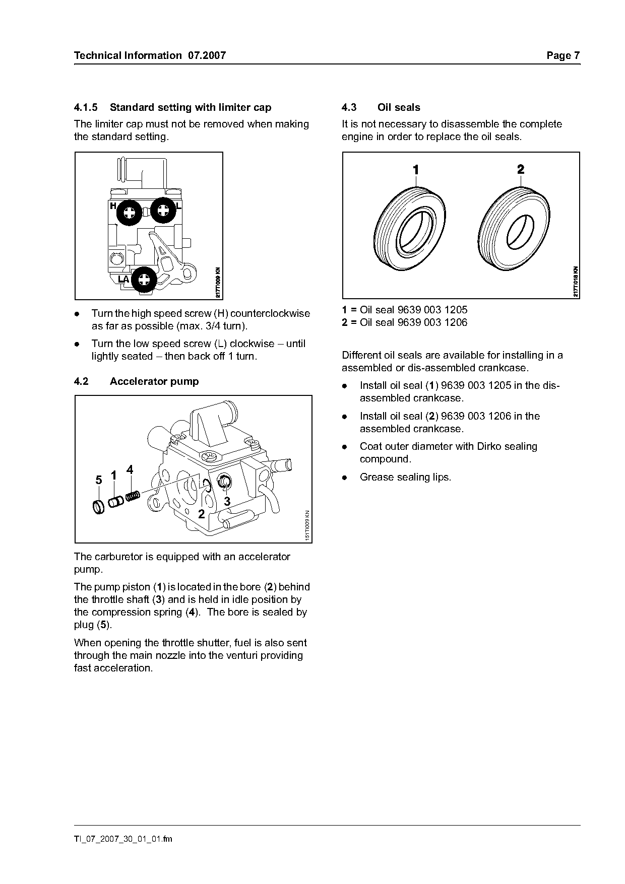
.     Turn the high speed screw (H) counterclockwise              1 = Oil seal 9639 003 1205
      as far as possible (max. 3/4 turn).                         2 = Oil seal 9639 003 1206

.     Turn the low speed screw (L) clockwise – until
      lightly seated – then back off 1 turn.                      Different oil seals are available for installing in a
                                                                  assembled or dis-assembled crankcase.
4.2      Accelerator pump                                         .     Install oil seal (1) 9639 003 1205 in the dis-
                                                                        assembled crankcase.
                                                                  .     Install oil seal (2) 9639 003 1206 in the
                                                                        assembled crankcase.
                                                                  .     Coat outer diameter with Dirko sealing
                                                                        compound.
             4
      5 1                                                         .     Grease sealing lips.

                                  3
                            2
                                                    151TI009 KN

The carburetor is equipped with an accelerator
pump.
The pump piston (1) is located in the bore (2) behind
the throttle shaft (3) and is held in idle position by
the compression spring (4). The bore is sealed by
plug (5).
When opening the throttle shutter, fuel is also sent
through the main nozzle into the venturi providing
fast acceleration.

TI_07_2007_30_01_01.fm
Page 8 of 10
Text of page 8 — search, copy, screen readers
Page 8                                                                   Technical Information 07.2007

4.4      Chain catcher                              4.5       Sprocket and worm

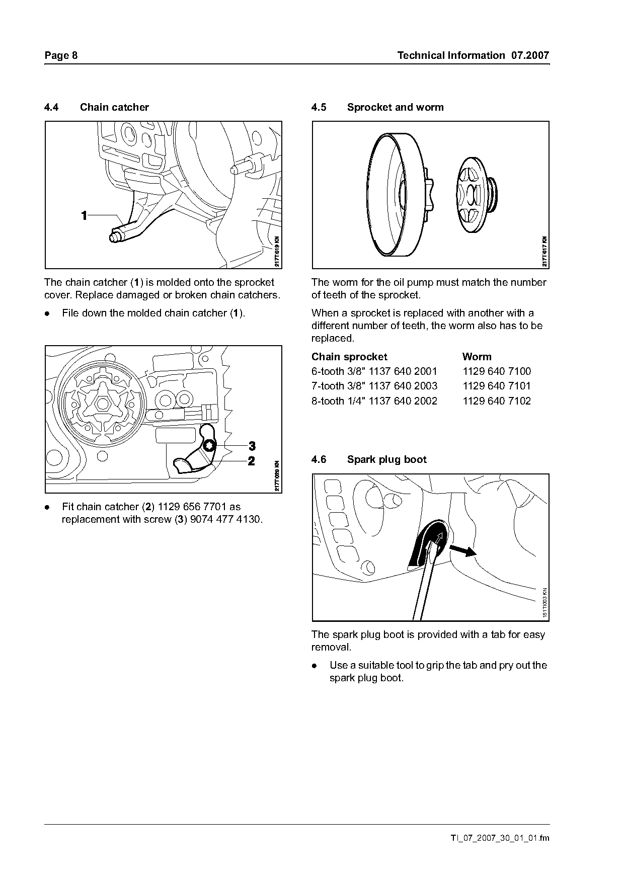
The chain catcher (1) is molded onto the sprocket   The worm for the oil pump must match the number
cover. Replace damaged or broken chain catchers.    of teeth of the sprocket.
.     File down the molded chain catcher (1).       When a sprocket is replaced with another with a
                                                    different number of teeth, the worm also has to be
                                                    replaced.
                                                    Chain sprocket                       Worm
                                                    6-tooth 3/8" 1137 640 2001           1129 640 7100
                                                    7-tooth 3/8" 1137 640 2003           1129 640 7101
                                                    8-tooth 1/4" 1137 640 2002           1129 640 7102

                                                    4.6       Spark plug boot

.     Fit chain catcher (2) 1129 656 7701 as
      replacement with screw (3) 9074 477 4130.

                                                                                                           151TI003 KN

                                                    The spark plug boot is provided with a tab for easy
                                                    removal.
                                                    .     Use a suitable tool to grip the tab and pry out the
                                                          spark plug boot.

                                                                                      TI_07_2007_30_01_01.fm
Page 9 of 10
Text of page 9 — search, copy, screen readers
Technical Information 07.2007                                                                                      Page 9

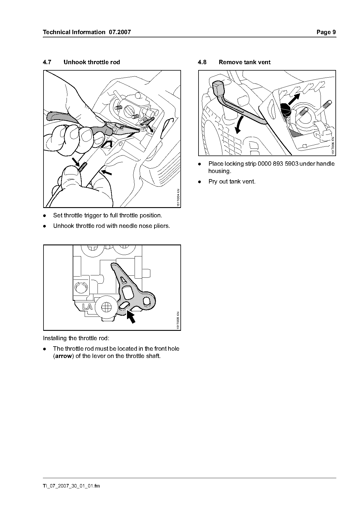
4.7       Unhook throttle rod                                         4.8      Remove tank vent

                                                                                                                        151TI006 KN
                                                                      .     Place locking strip 0000 893 5903 under handle
                                                                            housing.
                                                                      .     Pry out tank vent.
                                                        151TI004 KN

.     Set throttle trigger to full throttle position.
.     Unhook throttle rod with needle nose pliers.
                                                        151TI005 KN

Installing the throttle rod:
.     The throttle rod must be located in the front hole
      (arrow) of the lever on the throttle shaft.

TI_07_2007_30_01_01.fm
Page 10 of 10
Text of page 10 — search, copy, screen readers
Page 10                                                                                     Technical Information 07.2007

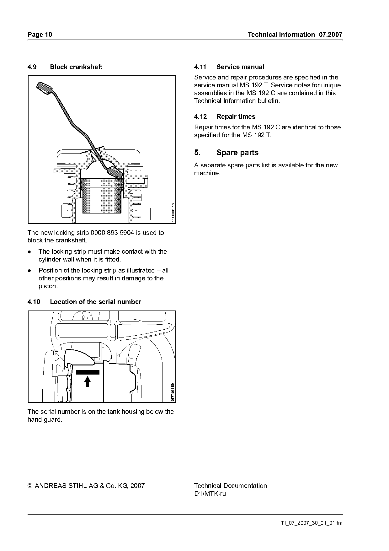
4.9       Block crankshaft                                               4.11    Service manual
                                                                         Service and repair procedures are specified in the
                                                                         service manual MS 192 T. Service notes for unique
                                                                         assemblies in the MS 192 C are contained in this
                                                                         Technical Information bulletin.

                                                                         4.12    Repair times
                                                                         Repair times for the MS 192 C are identical to those
                                                                         specified for the MS 192 T.

                                                                         5.      Spare parts
                                                                         A separate spare parts list is available for the new
                                                           151TI008 KN   machine.

The new locking strip 0000 893 5904 is used to
block the crankshaft.
.     The locking strip must make contact with the
      cylinder wall when it is fitted.
.     Position of the locking strip as illustrated – all
      other positions may result in damage to the
      piston.

4.10      Location of the serial number

The serial number is on the tank housing below the
hand guard.

© ANDREAS STIHL AG & Co. KG, 2007                                        Technical Documentation
                                                                         D1/MTK-ru

                                                                                                        TI_07_2007_30_01_01.fm
Most of these PDFs embed fonts with a shifted character map, so the text above was recovered rather than copied — read it as a faithful but imperfect transcription, and treat the page image above each block as the authority where the two disagree — the figures exist only there, because they are vector drawings that text extraction cannot keep.