Technical Information · issue 10 of 2007
Crankcase, Chain sprocket cover; Muffler and gasket, MS 660 only; Grommet; Summary
IssueTI 10/2007
Engine family 1122
Part changes (2)
| Was | Becomes | What the bulletin says |
|---|---|---|
| 1122 020 2113 | 1122 020 2116 | 1 Crankcase The previous crankcase 1122 020 2113 with bar studs 0000 953 6605 is now replaced by crankcase 1122 020 2116 with new bar studs 1138 664 2400. |
| 1128 664 1002 | 1128 664 1001 | If the new sprocket cover 1122 640 1707 is installed during maintenance/repair, the side panel with retaining lugs 1128 664 1002 must also be replaced by side panel 1128 664 1001 without retaining lugs. |
Full text
Page 1 of 6
Text of page 1 — search, copy, screen readers
STIH)

Technical Information                                                           10.2007

  Chain saws STIHL MS 650, MS 660 – Series 1122

  Contents
  1.    Crankcase, Chain sprocket cover
  2.    Muffler and gasket, MS 660 only
  3.    Grommet
  4.    Summary

  1.       Crankcase, Chain sprocket cover

  1.1      Crankcase
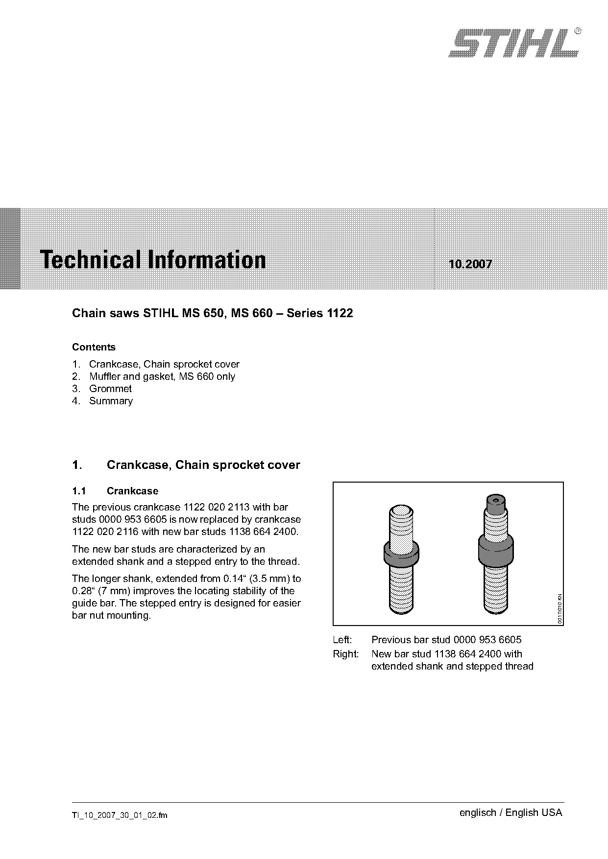
  The previous crankcase 1122 020 2113 with bar
  studs 0000 953 6605 is now replaced by crankcase
  1122 020 2116 with new bar studs 1138 664 2400.
  The new bar studs are characterized by an
  extended shank and a stepped entry to the thread.
  The longer shank, extended from 0.14“ (3.5 mm) to
  0.28“ (7 mm) improves the locating stability of the
                                                                                                      001TI010 KN

  guide bar. The stepped entry is designed for easier
  bar nut mounting.

                                                        Left:    Previous bar stud 0000 953 6605
                                                        Right:   New bar stud 1138 664 2400 with
                                                                 extended shank and stepped thread

  TI_10_2007_30_01_02.fm                                                          englisch / English USA
Page 2 of 6
Text of page 2 — search, copy, screen readers
Page 2                                                                            Technical Information 10.2007

1.2      Chain sprocket cover                                    1.3    Supply of spare parts
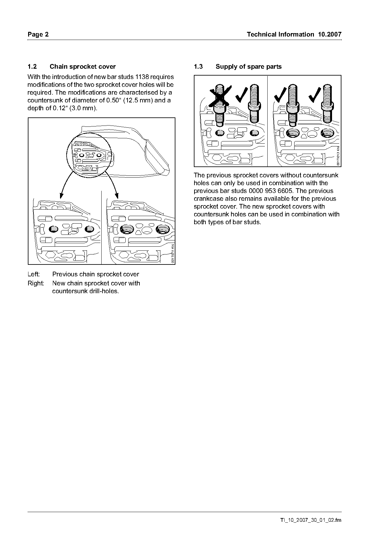
With the introduction of new bar studs 1138 requires
modifications of the two sprocket cover holes will be
required. The modifications are characterised by a
countersunk of diameter of 0.50“ (12.5 mm) and a
depth of 0.12“ (3.0 mm).

                                                                                                                  001TI013 KN
                                                                 The previous sprocket covers without countersunk
                                                                 holes can only be used in combination with the
                                                                 previous bar studs 0000 953 6605. The previous
                                                                 crankcase also remains available for the previous
                                                                 sprocket cover. The new sprocket covers with
                                                                 countersunk holes can be used in combination with
                                                                 both types of bar studs.
                                                   001TI011 KN

Left:    Previous chain sprocket cover
Right:   New chain sprocket cover with
         countersunk drill-holes.

                                                                                              TI_10_2007_30_01_02.fm
Page 3 of 6
Text of page 3 — search, copy, screen readers
Technical Information 10.2007                                                                                 Page 3

1.4     Side panel with retaining lugs                          Service note
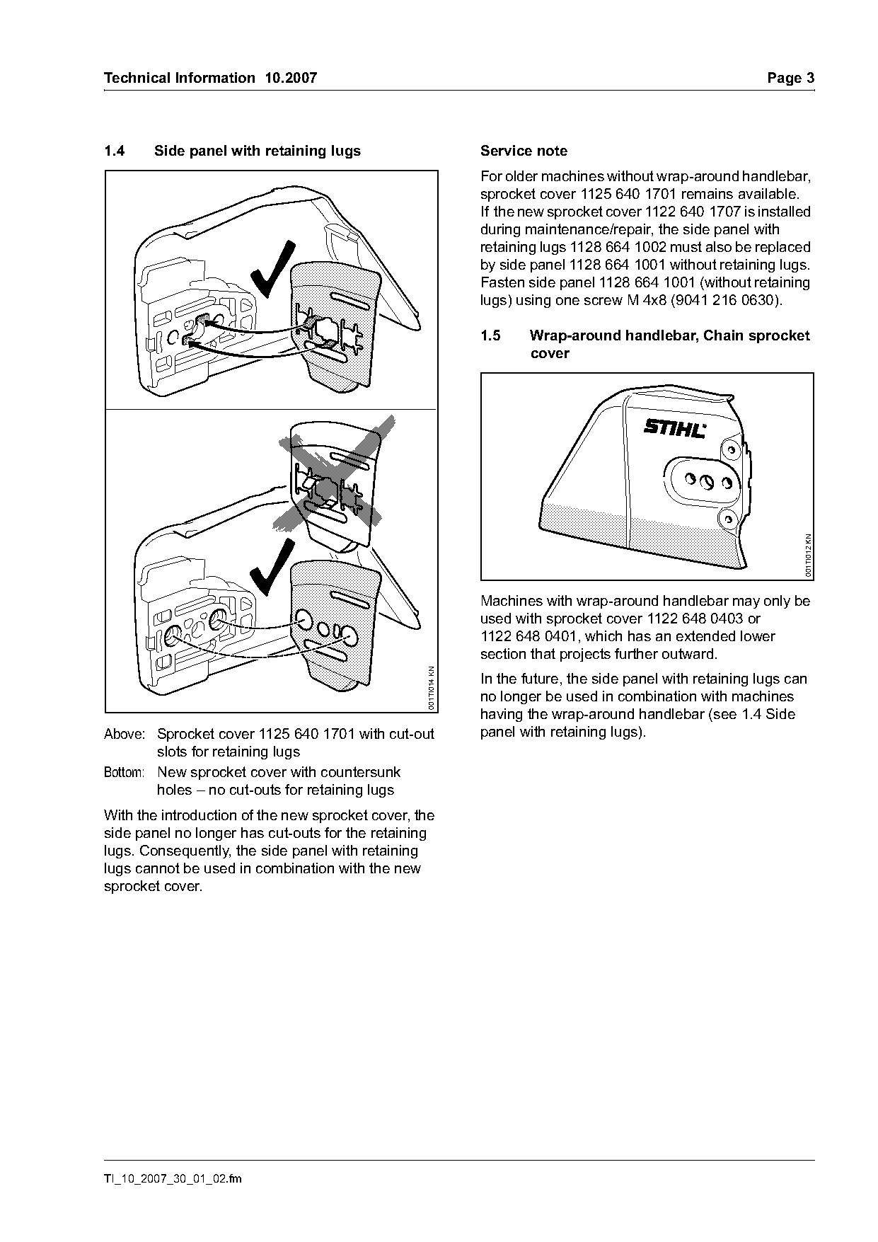
                                                                For older machines without wrap-around handlebar,
                                                                sprocket cover 1125 640 1701 remains available.
                                                                If the new sprocket cover 1122 640 1707 is installed
                                                                during maintenance/repair, the side panel with
                                                                retaining lugs 1128 664 1002 must also be replaced
                                                                by side panel 1128 664 1001 without retaining lugs.
                                                                Fasten side panel 1128 664 1001 (without retaining
                                                                lugs) using one screw M 4x8 (9041 216 0630).

                                                                1.5     Wrap-around handlebar, Chain sprocket
                                                                        cover

                                                                                                                    001TI012 KN
                                                                Machines with wrap-around handlebar may only be
                                                                used with sprocket cover 1122 648 0403 or
                                                                1122 648 0401, which has an extended lower
                                                                section that projects further outward.
                                                  001TI014 KN

                                                                In the future, the side panel with retaining lugs can
                                                                no longer be used in combination with machines
                                                                having the wrap-around handlebar (see 1.4 Side
Above: Sprocket cover 1125 640 1701 with cut-out                panel with retaining lugs).
        slots for retaining lugs
Bottom: New sprocket cover with countersunk
        holes – no cut-outs for retaining lugs
With the introduction of the new sprocket cover, the
side panel no longer has cut-outs for the retaining
lugs. Consequently, the side panel with retaining
lugs cannot be used in combination with the new
sprocket cover.

TI_10_2007_30_01_02.fm
Page 4 of 6
Text of page 4 — search, copy, screen readers
Page 4                                                                           Technical Information 10.2007

1.6      Special tools                                        1.6.2   Mounting tool
                                                                      (Clutch side 5910 890 2205
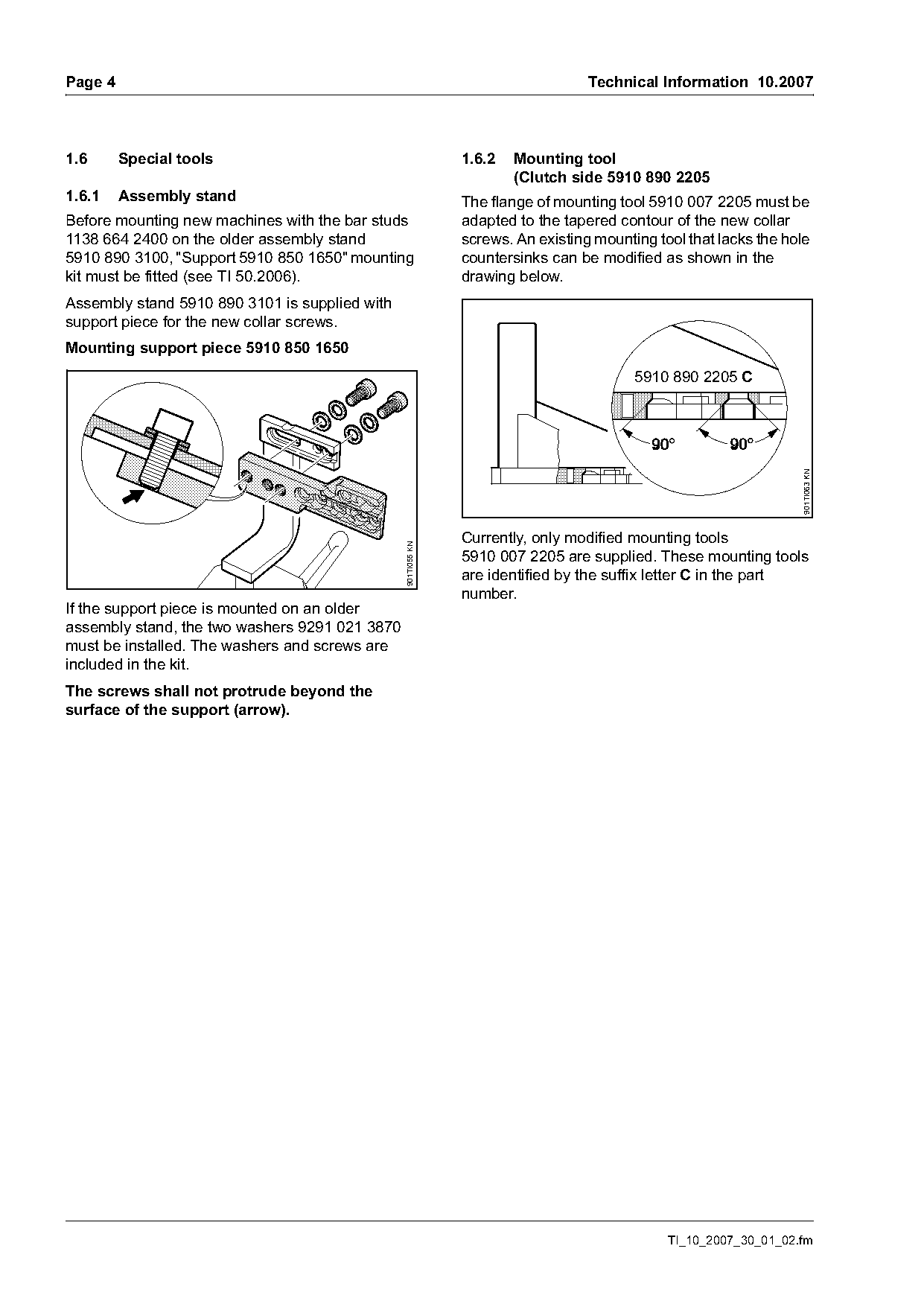
1.6.1    Assembly stand                                       The flange of mounting tool 5910 007 2205 must be
Before mounting new machines with the bar studs               adapted to the tapered contour of the new collar
1138 664 2400 on the older assembly stand                     screws. An existing mounting tool that lacks the hole
5910 890 3100, "Support 5910 850 1650" mounting               countersinks can be modified as shown in the
kit must be fitted (see TI 50.2006).                          drawing below.
Assembly stand 5910 890 3101 is supplied with
support piece for the new collar screws.
Mounting support piece 5910 850 1650
                                                                                        5910 890 2205 C

                                                                                                                 901TI063 KN
                                                              Currently, only modified mounting tools
                                                901TI055 KN

                                                              5910 007 2205 are supplied. These mounting tools
                                                              are identified by the suffix letter C in the part
                                                              number.
If the support piece is mounted on an older
assembly stand, the two washers 9291 021 3870
must be installed. The washers and screws are
included in the kit.
The screws shall not protrude beyond the
surface of the support (arrow).

                                                                                             TI_10_2007_30_01_02.fm
Page 5 of 6
Text of page 5 — search, copy, screen readers
Technical Information 10.2007                                                                               Page 5

2.     Muffler and gasket                                       3.       Grommet
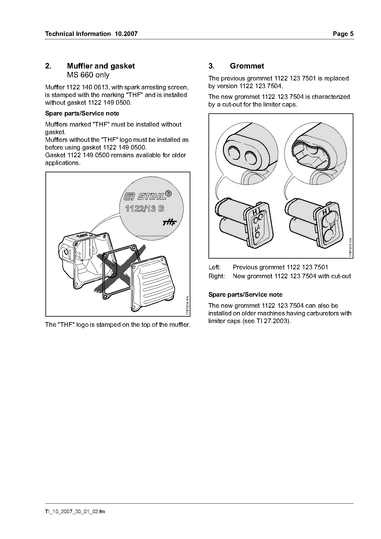
       MS 660 only                                              The previous grommet 1122 123 7501 is replaced
Muffler 1122 140 0613, with spark arresting screen,             by version 1122 123 7504.
is stamped with the marking "THF" and is installed              The new grommet 1122 123 7504 is characterized
without gasket 1122 149 0500.                                   by a cut-out for the limiter caps.
Spare parts/Service note
Mufflers marked "THF" must be installed without
gasket.
Mufflers without the "THF" logo must be installed as
before using gasket 1122 149 0500.
Gasket 1122 149 0500 remains available for older
applications.

                                                                                                                 178TI015 KN
                                                                Left:    Previous grommet 1122 123 7501
                                                                Right:   New grommet 1122 123 7504 with cut-out

                                                                Spare parts/Service note
                                                  178TI014 KN

                                                                The new grommet 1122 123 7504 can also be
                                                                installed on older machines having carburetors with
                                                                limiter caps (see TI 27.2003).
The "THF" logo is stamped on the top of the muffler.

TI_10_2007_30_01_02.fm
Page 6 of 6
Text of page 6 — search, copy, screen readers
Page 6                                                                           Technical Information 10.2007

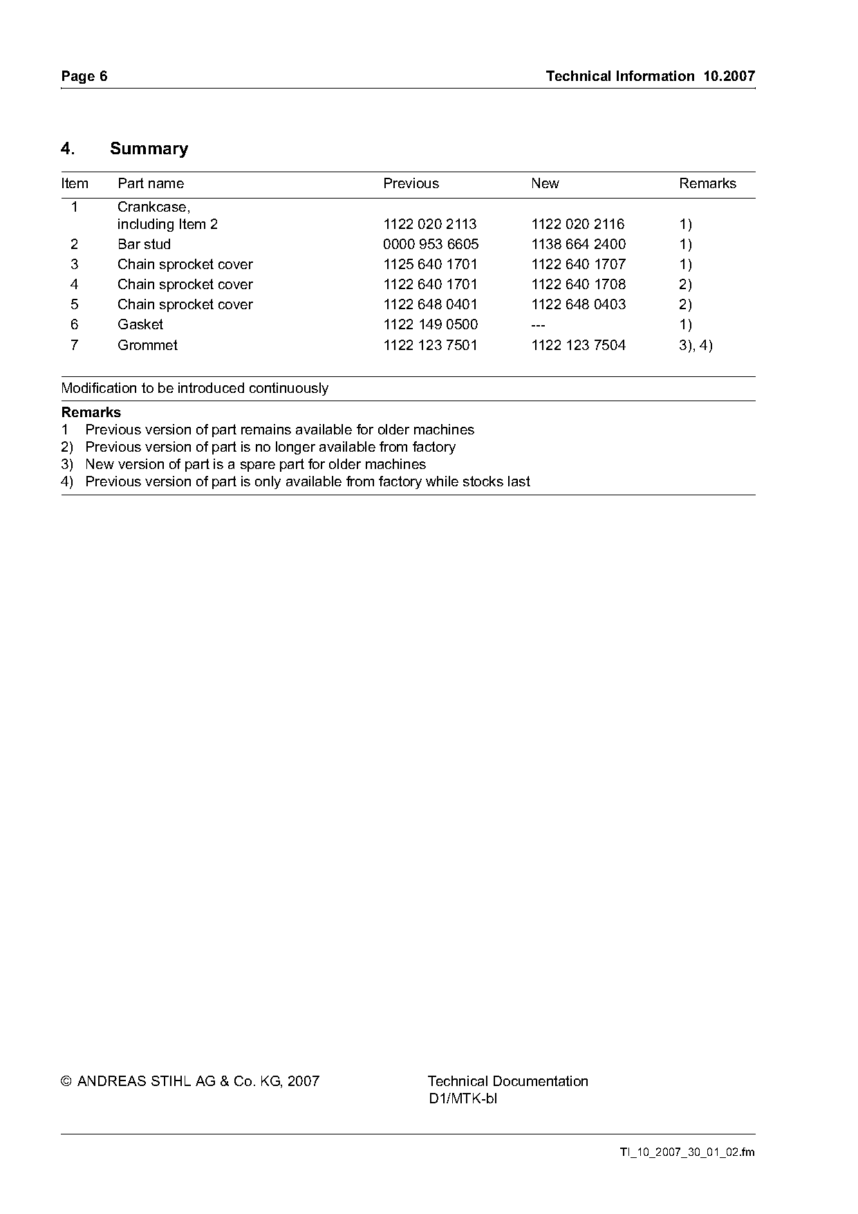
4.       Summary
Item     Part name                                  Previous                   New                  Remarks
 1       Crankcase,
         including Item 2                           1122 020 2113              1122 020 2116        1)
 2       Bar stud                                   0000 953 6605              1138 664 2400        1)
 3       Chain sprocket cover                       1125 640 1701              1122 640 1707        1)
 4       Chain sprocket cover                       1122 640 1701              1122 640 1708        2)
 5       Chain sprocket cover                       1122 648 0401              1122 648 0403        2)
 6       Gasket                                     1122 149 0500              ---                  1)
 7       Grommet                                    1122 123 7501              1122 123 7504        3), 4)

Modification to be introduced continuously
Remarks
1 Previous version of part remains available for older machines
2) Previous version of part is no longer available from factory
3) New version of part is a spare part for older machines
4) Previous version of part is only available from factory while stocks last

© ANDREAS STIHL AG & Co. KG, 2007                          Technical Documentation
                                                           D1/MTK-bl

                                                                                           TI_10_2007_30_01_02.fm
Most of these PDFs embed fonts with a shifted character map, so the text above was recovered rather than copied — read it as a faithful but imperfect transcription, and treat the page image above each block as the authority where the two disagree — the figures exist only there, because they are vector drawings that text extraction cannot keep.