Technical Information · issue 22 of 2007
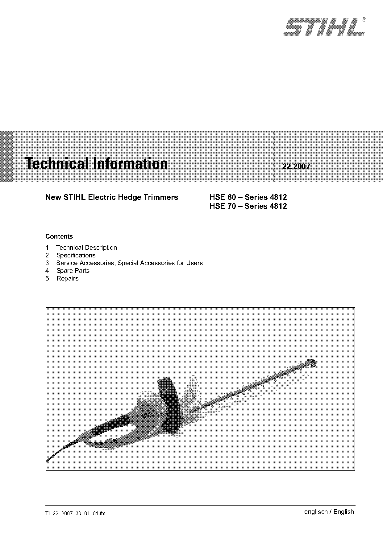
New STIHL Electric Hedge Trimmers
Model completely assembled
IssueTI 22/2007
Full text
Page 1 of 6
Text of page 1 — search, copy, screen readers
STIH)

Technical Information                                                         22.2007

  New STIHL Electric Hedge Trimmers                         HSE 60 – Series 4812
                                                            HSE 70 – Series 4812

  Contents
  1.   Technical Description
  2.   Specifications
  3.   Service Accessories, Special Accessories for Users
  4.   Spare Parts
  5.   Repairs

  TI_22_2007_30_01_01.fm                                                           englisch / English
Page 2 of 6
Text of page 2 — search, copy, screen readers
Page 2                                                                   Technical Information 22.2007

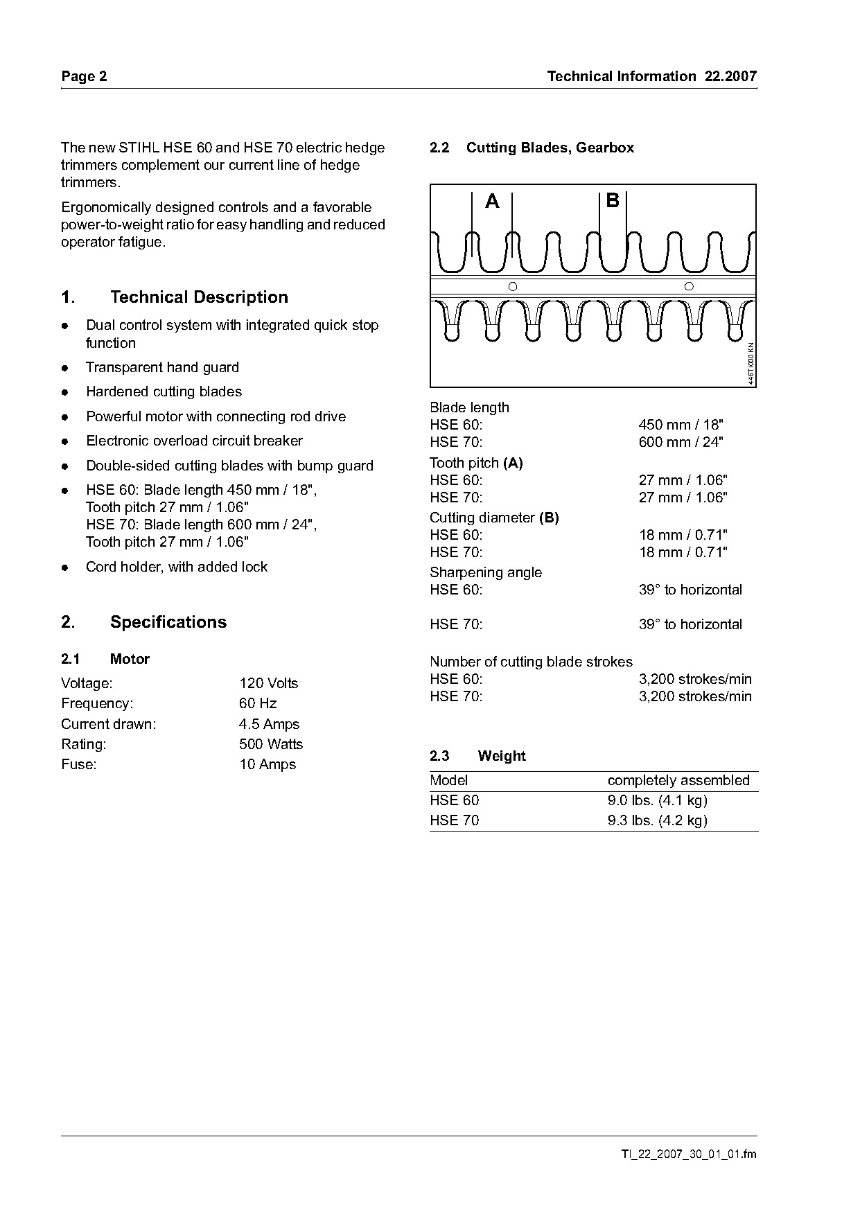
The new STIHL HSE 60 and HSE 70 electric hedge         2.2   Cutting Blades, Gearbox
trimmers complement our current line of hedge
trimmers.
Ergonomically designed controls and a favorable                  A               B
power-to-weight ratio for easy handling and reduced
operator fatigue.

1.       Technical Description
.     Dual control system with integrated quick stop
      function

                                                                                                           446TI000 KN
.     Transparent hand guard
.     Hardened cutting blades
                                                       Blade length
.     Powerful motor with connecting rod drive
                                                       HSE 60:                         450 mm / 18"
.     Electronic overload circuit breaker              HSE 70:                         600 mm / 24"
.     Double-sided cutting blades with bump guard      Tooth pitch (A)
                                                       HSE 60:                         27 mm / 1.06"
.     HSE 60: Blade length 450 mm / 18",
                                                       HSE 70:                         27 mm / 1.06"
      Tooth pitch 27 mm / 1.06"
      HSE 70: Blade length 600 mm / 24",               Cutting diameter (B)
      Tooth pitch 27 mm / 1.06"                        HSE 60:                         18 mm / 0.71"
                                                       HSE 70:                         18 mm / 0.71"
.     Cord holder, with added lock                     Sharpening angle
                                                       HSE 60:                         39° to horizontal

2.       Specifications                                HSE 70:                         39° to horizontal

2.1      Motor                                         Number of cutting blade strokes
Voltage:                      120 Volts                HSE 60:                         3,200 strokes/min
Frequency:                    60 Hz                    HSE 70:                         3,200 strokes/min
Current drawn:                4.5 Amps
Rating:                       500 Watts
                                                       2.3    Weight
Fuse:                         10 Amps
                                                       Model                      completely assembled
                                                       HSE 60                     9.0 lbs. (4.1 kg)
                                                       HSE 70                     9.3 lbs. (4.2 kg)

                                                                                     TI_22_2007_30_01_01.fm
Page 3 of 6
Text of page 3 — search, copy, screen readers
Technical Information 22.2007                                                                        Page 3

3.      Service Accessories, Special
        Accessories for Users
Description                        Part #                Application
STIHL gear lubricant for HSE       0781 120 1011         Gearbox lubricant
(80 g tube)
STIHL resin solvent                0782 420 1002         Blade cleaner and lubricant
(300 ml can)

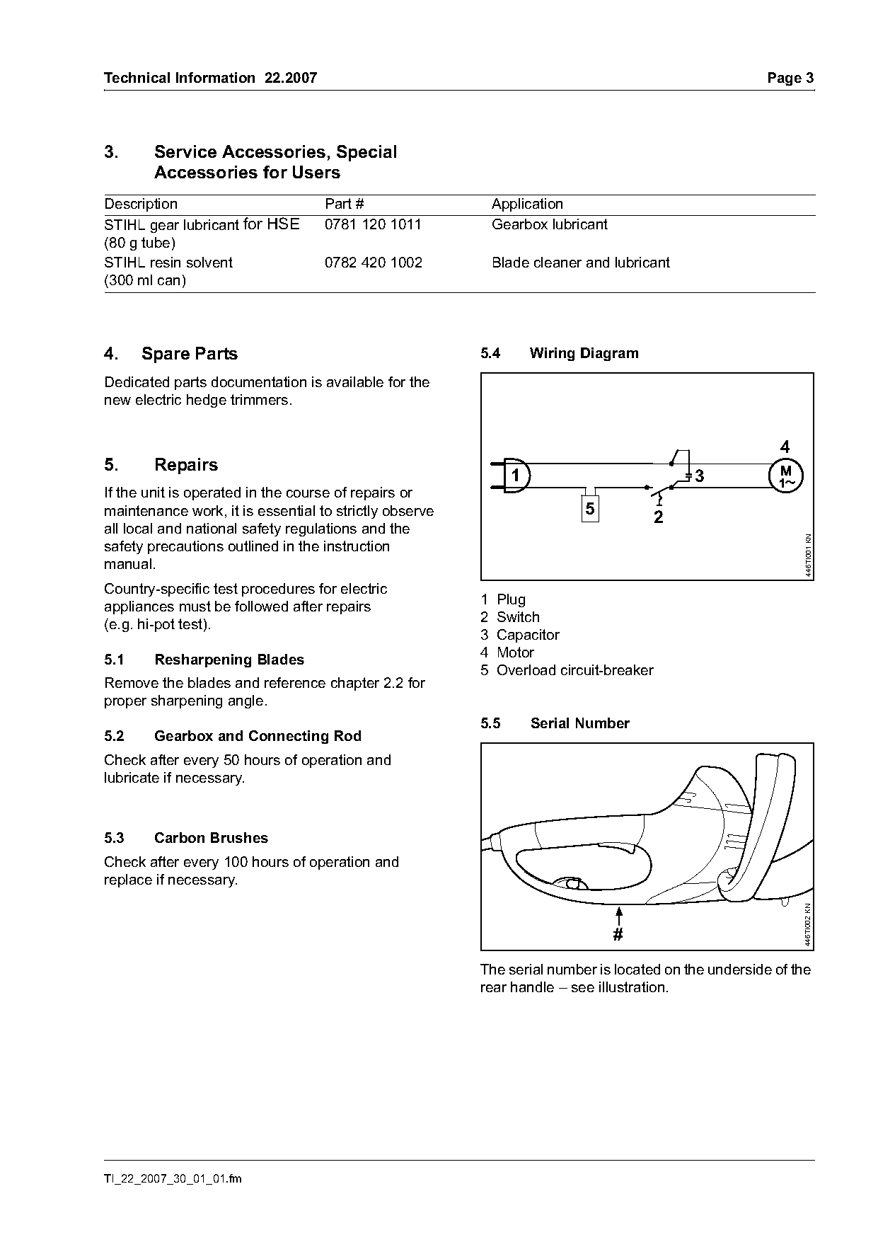
4.    Spare Parts                                       5.4       Wiring Diagram
Dedicated parts documentation is available for the
new electric hedge trimmers.

                                                                                                       4
5.      Repairs
                                                              1                          3
If the unit is operated in the course of repairs or
maintenance work, it is essential to strictly observe                    5           2
all local and national safety regulations and the

                                                                                                           446TI001 KN
safety precautions outlined in the instruction
manual.
Country-specific test procedures for electric
appliances must be followed after repairs               1 Plug
(e.g. hi-pot test).                                     2 Switch
                                                        3 Capacitor
5.1     Resharpening Blades                             4 Motor
                                                        5 Overload circuit-breaker
Remove the blades and reference chapter 2.2 for
proper sharpening angle.
                                                        5.5       Serial Number
5.2     Gearbox and Connecting Rod
Check after every 50 hours of operation and
lubricate if necessary.

5.3     Carbon Brushes
Check after every 100 hours of operation and
replace if necessary.
                                                                                                           446TI002 KN

                                                                             #
                                                        The serial number is located on the underside of the
                                                        rear handle – see illustration.

TI_22_2007_30_01_01.fm
Page 4 of 6
Text of page 4 — search, copy, screen readers
Page 4                                                                                  Technical Information 22.2007

5.6       Overload Circuit Breaker
The overload circuit breaker interrupts the power
supply to the machine in the event of a mechanical
overload.                                                                                               5
If the overload circuit breaker has tripped,
disconnect the power supply:
                                                                                                   5
.     Release controls on front and rear handles
.     Disconnect the extension cord from the power

                                                                                                                          446TI004 KN
      supply
.     Verify the cause of the mechanical overload
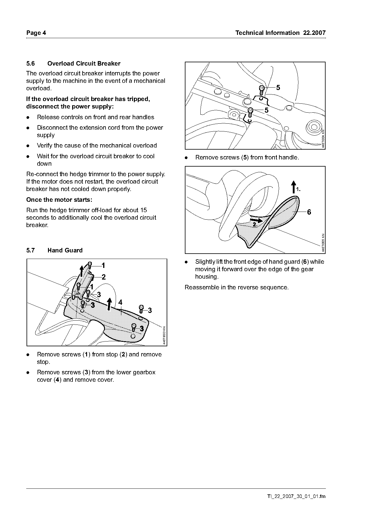
.     Wait for the overload circuit breaker to cool                 .   Remove screws (5) from front handle.
      down
Re-connect the hedge trimmer to the power supply.
If the motor does not restart, the overload circuit
breaker has not cooled down properly.                                                                           1.
Once the motor starts:
Run the hedge trimmer off-load for about 15                                                                          6
seconds to additionally cool the overload circuit
breaker.

                                                                                                                          446TI005 KN
5.7       Hand Guard
                                                                    .   Slightly lift the front edge of hand guard (6) while
                                  1                                     moving it forward over the edge of the gear
                                  2                                     housing.
                          1                                         Reassemble in the reverse sequence.
                              3
                                      4
                                                3
                                                      446TI003 KN

.     Remove screws (1) from stop (2) and remove
      stop.
.     Remove screws (3) from the lower gearbox
      cover (4) and remove cover.

                                                                                                     TI_22_2007_30_01_01.fm
Page 5 of 6
Text of page 5 — search, copy, screen readers
Technical Information 22.2007                                    Page 5

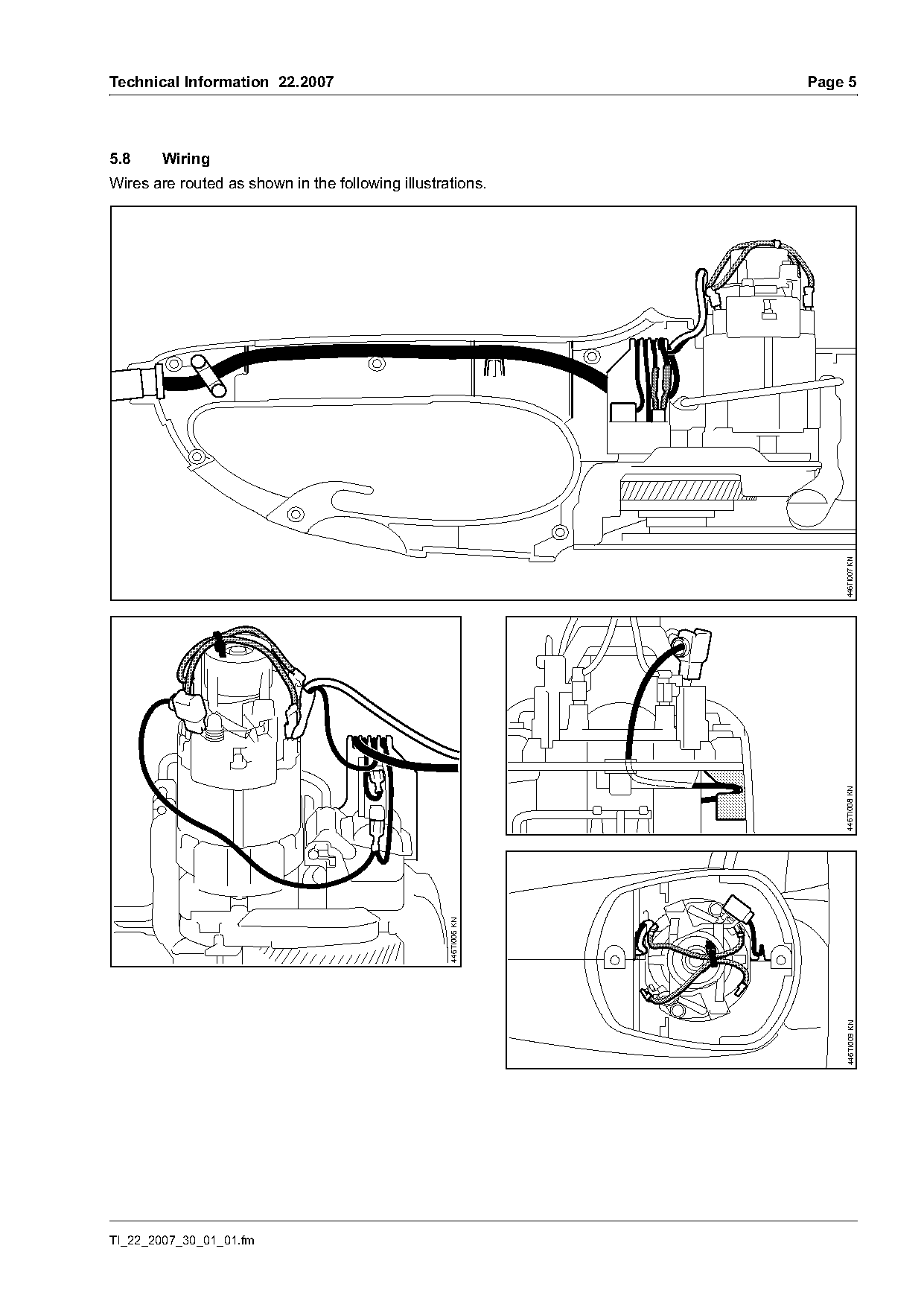
5.8     Wiring
Wires are routed as shown in the following illustrations.

                                                                     446TI007 KN
                                                                     446TI008 KN
                                                   446TI006 KN

                                                                     446TI009 KN

TI_22_2007_30_01_01.fm
Page 6 of 6
Text of page 6 — search, copy, screen readers
Page 6                                                                Technical Information 22.2007

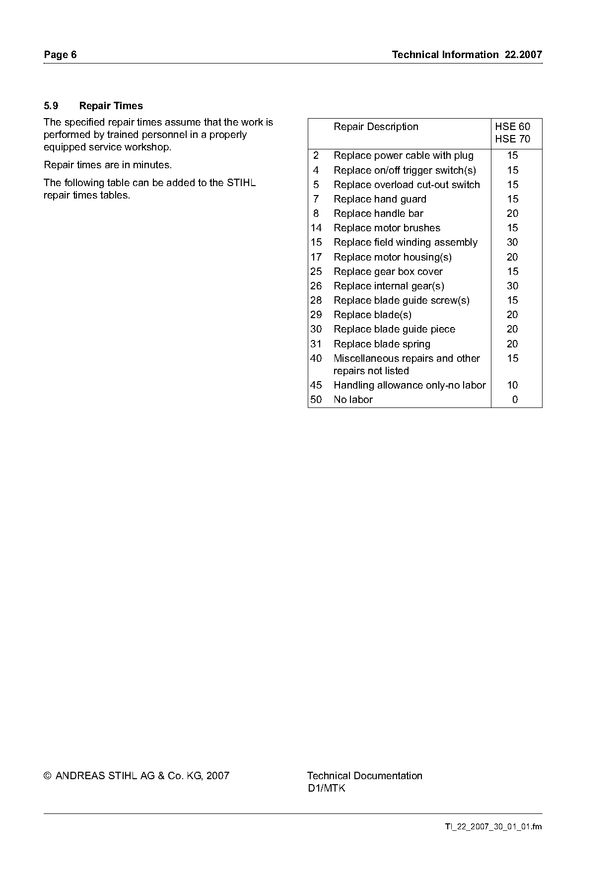
5.9      Repair Times
The specified repair times assume that the work is        Repair Description                 HSE 60
performed by trained personnel in a properly                                                 HSE 70
equipped service workshop.
                                                     2    Replace power cable with plug        15
Repair times are in minutes.
                                                     4    Replace on/off trigger switch(s)     15
The following table can be added to the STIHL        5    Replace overload cut-out switch      15
repair times tables.                                 7    Replace hand guard                   15
                                                     8    Replace handle bar                   20
                                                     14   Replace motor brushes                15
                                                     15   Replace field winding assembly       30
                                                     17   Replace motor housing(s)             20
                                                     25   Replace gear box cover               15
                                                     26   Replace internal gear(s)             30
                                                     28   Replace blade guide screw(s)         15
                                                     29   Replace blade(s)                     20
                                                     30   Replace blade guide piece            20
                                                     31   Replace blade spring                 20
                                                     40   Miscellaneous repairs and other      15
                                                          repairs not listed
                                                     45   Handling allowance only-no labor     10
                                                     50   No labor                              0

© ANDREAS STIHL AG & Co. KG, 2007                    Technical Documentation
                                                     D1/MTK

                                                                                 TI_22_2007_30_01_01.fm
Most of these PDFs embed fonts with a shifted character map, so the text above was recovered rather than copied — read it as a faithful but imperfect transcription, and treat the page image above each block as the authority where the two disagree — the figures exist only there, because they are vector drawings that text extraction cannot keep.