Technical Information · issue 24 of 2007
New HL 90 K Hedge Trimmer
Model Overall length
IssueTI 24/2007
Full text
Page 1 of 8
Text of page 1 — search, copy, screen readers
STIH)

Technical Information                                                                 24.2007

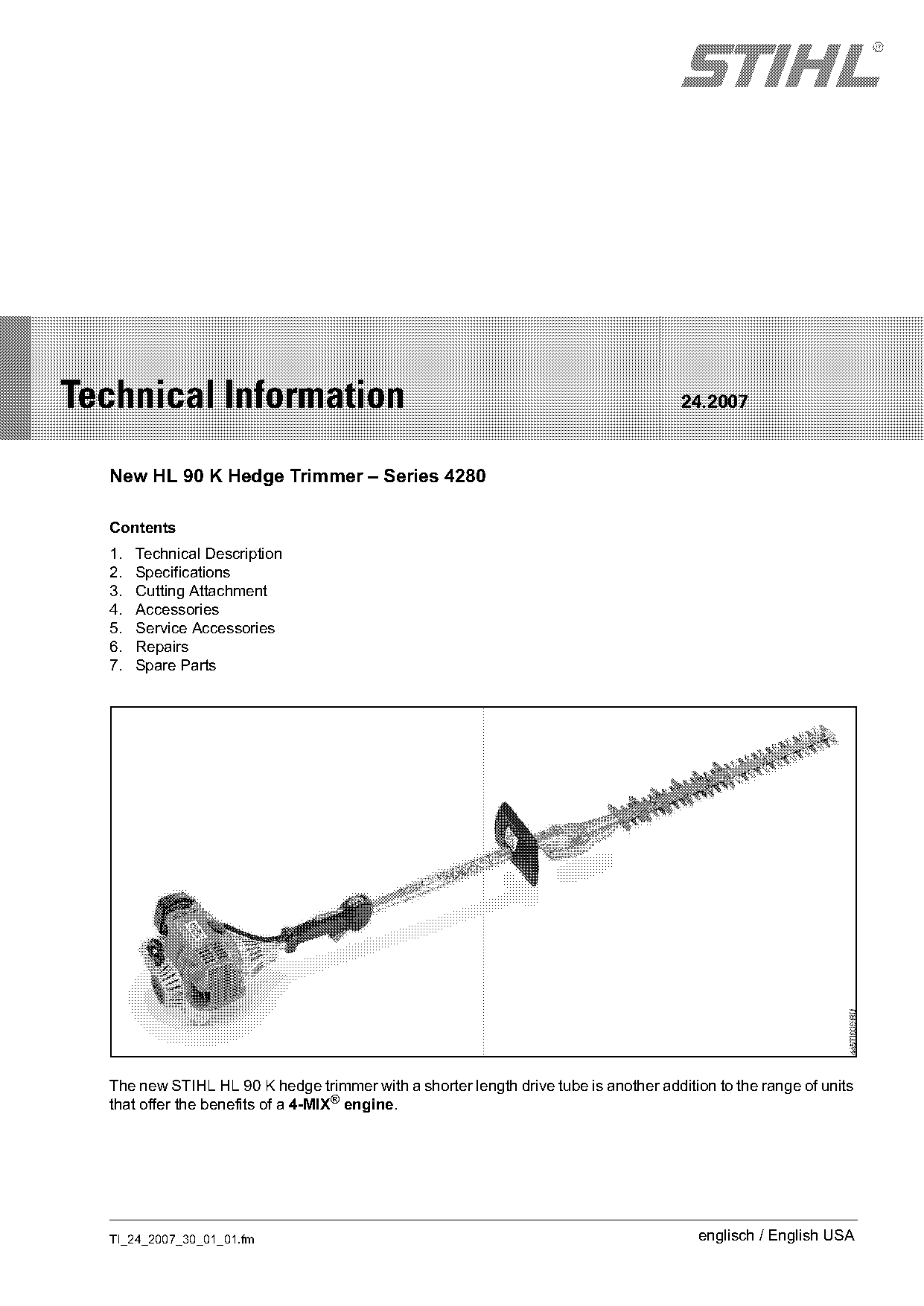
  New HL 90 K Hedge Trimmer – Series 4280

  Contents
  1.   Technical Description
  2.   Specifications
  3.   Cutting Attachment
  4.   Accessories
  5.   Service Accessories
  6.   Repairs
  7.   Spare Parts

  The new STIHL HL 90 K hedge trimmer with a shorter length drive tube is another addition to the range of units
  that offer the benefits of a 4-MIX® engine.

  TI_24_2007_30_01_01.fm                                                                 englisch / English USA
Page 2 of 8
Text of page 2 — search, copy, screen readers
Page 2                                                                    Technical Information 24.2007

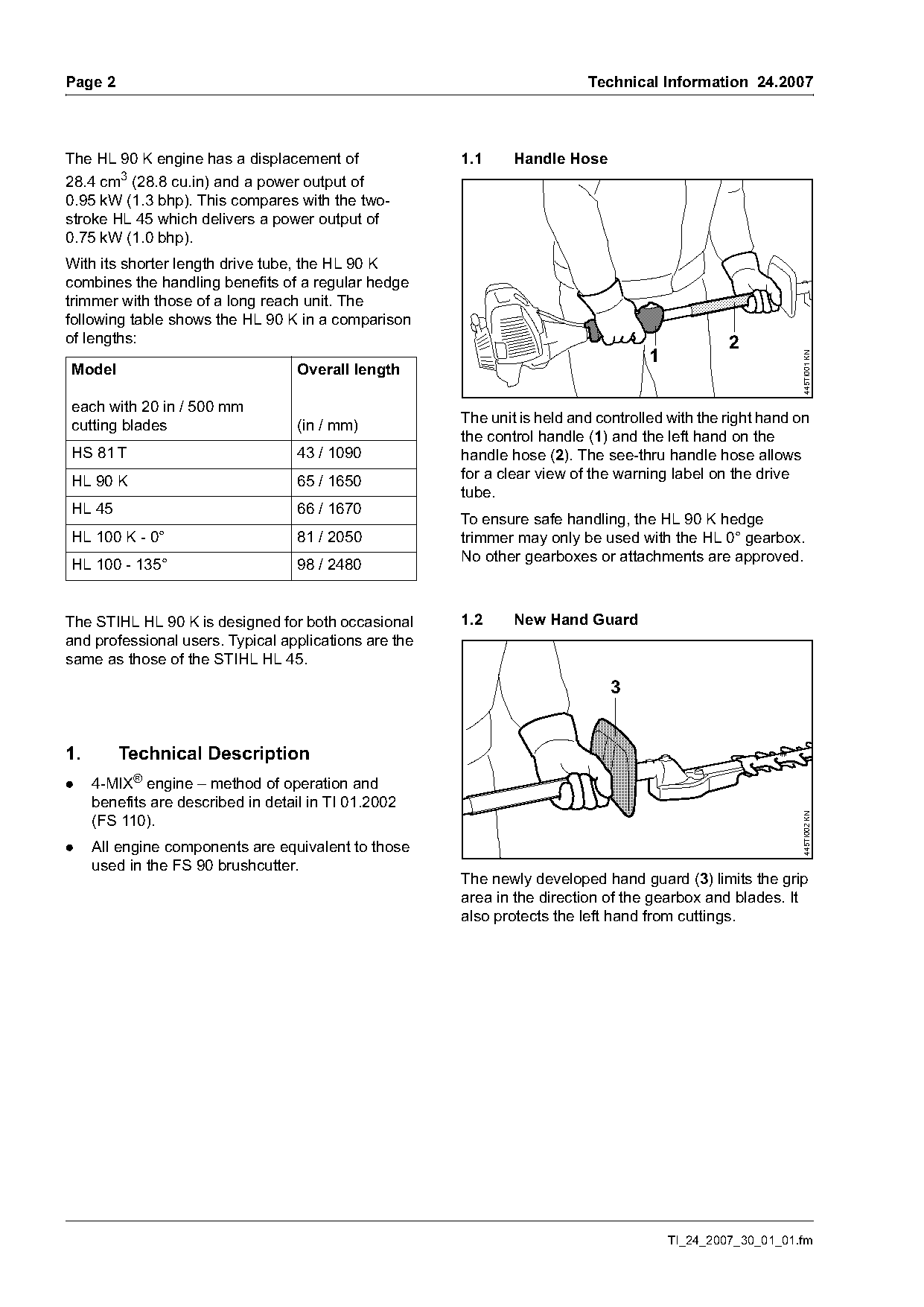
The HL 90 K engine has a displacement of               1.1     Handle Hose
28.4 cm3 (28.8 cu.in) and a power output of
0.95 kW (1.3 bhp). This compares with the two-
stroke HL 45 which delivers a power output of
0.75 kW (1.0 bhp).
With its shorter length drive tube, the HL 90 K
combines the handling benefits of a regular hedge
trimmer with those of a long reach unit. The
following table shows the HL 90 K in a comparison
of lengths:                                                                                      2
                                                                                    1

                                                                                                            445TI001 KN
Model                               Overall length

each with 20 in / 500 mm
cutting blades                      (in / mm)          The unit is held and controlled with the right hand on
                                                       the control handle (1) and the left hand on the
HS 81 T                             43 / 1090          handle hose (2). The see-thru handle hose allows
HL 90 K                             65 / 1650          for a clear view of the warning label on the drive
                                                       tube.
HL 45                               66 / 1670
                                                       To ensure safe handling, the HL 90 K hedge
HL 100 K - 0°                       81 / 2050          trimmer may only be used with the HL 0° gearbox.
                                                       No other gearboxes or attachments are approved.
HL 100 - 135°                       98 / 2480

The STIHL HL 90 K is designed for both occasional      1.2     New Hand Guard
and professional users. Typical applications are the
same as those of the STIHL HL 45.
                                                                              3

1.       Technical Description
.    4-MIX® engine – method of operation and
     benefits are described in detail in TI 01.2002                                                         445TI002 KN

     (FS 110).
.    All engine components are equivalent to those
     used in the FS 90 brushcutter.
                                                       The newly developed hand guard (3) limits the grip
                                                       area in the direction of the gearbox and blades. It
                                                       also protects the left hand from cuttings.

                                                                                        TI_24_2007_30_01_01.fm
Page 3 of 8
Text of page 3 — search, copy, screen readers
Technical Information 24.2007                                                                                       Page 3

1.3    Cutter Guard                                                   1.4     Tip Guard


                                                  445TI003 KN

                                                                                                                           445TI004 KN
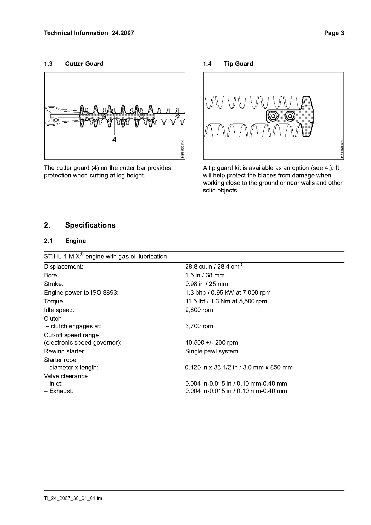
The cutter guard (4) on the cutter bar provides                       A tip guard kit is available as an option (see 4.). It
protection when cutting at leg height.                                will help protect the blades from damage when
                                                                      working close to the ground or near walls and other
                                                                      solid objects.

2.     Specifications

2.1     Engine

STIHL 4-MIX® engine with gas-oil lubrication
Displacement:                                                   28.8 cu.in / 28.4 cm3
Bore:                                                           1.5 in / 38 mm
Stroke:                                                         0.98 in / 25 mm
Engine power to ISO 8893:                                       1.3 bhp / 0.95 kW at 7,000 rpm
Torque:                                                         11.5 lbf / 1.3 Nm at 5,500 rpm
Idle speed:                                                     2,800 rpm
Clutch
 – clutch engages at:                                           3,700 rpm
Cut-off speed range
(electronic speed governor):                                    10,500 +/- 200 rpm
Rewind starter:                                                 Single pawl system
Starter rope
– diameter x length:                                            0.120 in x 33 1/2 in / 3.0 mm x 850 mm
Valve clearance
– Inlet:                                                        0.004 in-0.015 in / 0.10 mm-0.40 mm
– Exhaust:                                                      0.004 in-0.015 in / 0.10 mm-0.40 mm

TI_24_2007_30_01_01.fm
Page 4 of 8
Text of page 4 — search, copy, screen readers
Page 4                                                                         Technical Information 24.2007

2.2      Ignition System
Ignition module with integral electronic speed governor
Spark plug (resistor type):                   Bosch USR 7AC
Electrode gap:                                0.02 in / 0.5 mm

2.3      Fuel System
The STIHL 4-MIX® engine features gasoline-oil lubrication and must be operated on a fuel mixture of
gasoline and engine oil.

2.3.1    Fuel
Fuel mix:                                    see instruction manual

2.3.2    Fuel Tank
Capacity:                                    18 fl.oz (1.12 li.pt) / 530 cm3 (0.53 l)

2.3.3    Carburetor

All position diaphragm carburetor with integral fuel pump
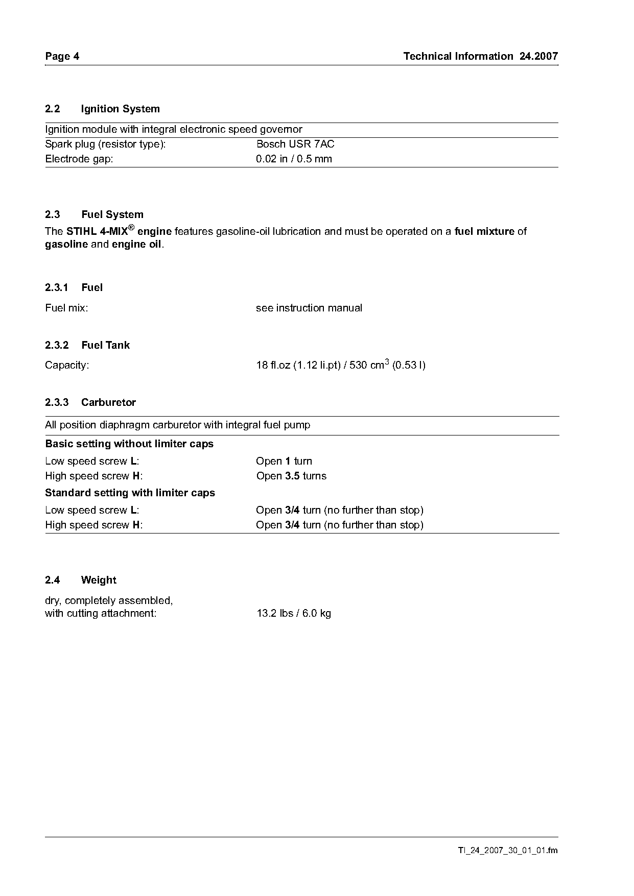
Basic setting without limiter caps
Low speed screw L:                           Open 1 turn
High speed screw H:                          Open 3.5 turns
Standard setting with limiter caps
Low speed screw L:                           Open 3/4 turn (no further than stop)
High speed screw H:                          Open 3/4 turn (no further than stop)

2.4      Weight
dry, completely assembled,
with cutting attachment:                     13.2 lbs / 6.0 kg

                                                                                         TI_24_2007_30_01_01.fm
Page 5 of 8
Text of page 5 — search, copy, screen readers
Technical Information 24.2007                                                                Page 5

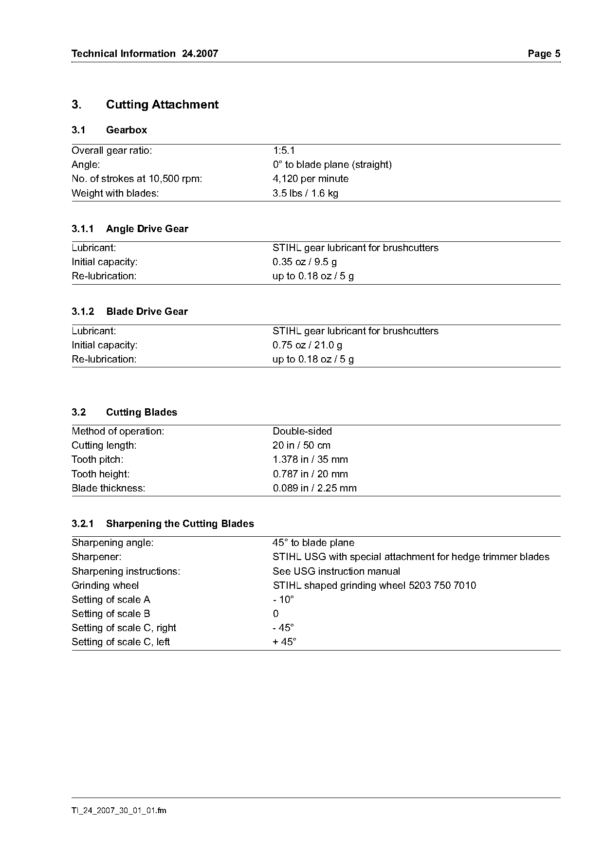
3.      Cutting Attachment

3.1     Gearbox

Overall gear ratio:                     1:5.1
Angle:                                  0° to blade plane (straight)
No. of strokes at 10,500 rpm:           4,120 per minute
Weight with blades:                     3.5 lbs / 1.6 kg

3.1.1   Angle Drive Gear
Lubricant:                              STIHL gear lubricant for brushcutters
Initial capacity:                       0.35 oz / 9.5 g
Re-lubrication:                         up to 0.18 oz / 5 g

3.1.2   Blade Drive Gear
Lubricant:                              STIHL gear lubricant for brushcutters
Initial capacity:                       0.75 oz / 21.0 g
Re-lubrication:                         up to 0.18 oz / 5 g

3.2     Cutting Blades
Method of operation:                    Double-sided
Cutting length:                         20 in / 50 cm
Tooth pitch:                            1.378 in / 35 mm
Tooth height:                           0.787 in / 20 mm
Blade thickness:                        0.089 in / 2.25 mm

3.2.1   Sharpening the Cutting Blades
Sharpening angle:                       45° to blade plane
Sharpener:                              STIHL USG with special attachment for hedge trimmer blades
Sharpening instructions:                See USG instruction manual
Grinding wheel                          STIHL shaped grinding wheel 5203 750 7010
Setting of scale A                      - 10°
Setting of scale B                      0
Setting of scale C, right               - 45°
Setting of scale C, left                + 45°

TI_24_2007_30_01_01.fm
Page 6 of 8
Text of page 6 — search, copy, screen readers
Page 6                                                                          Technical Information 24.2007

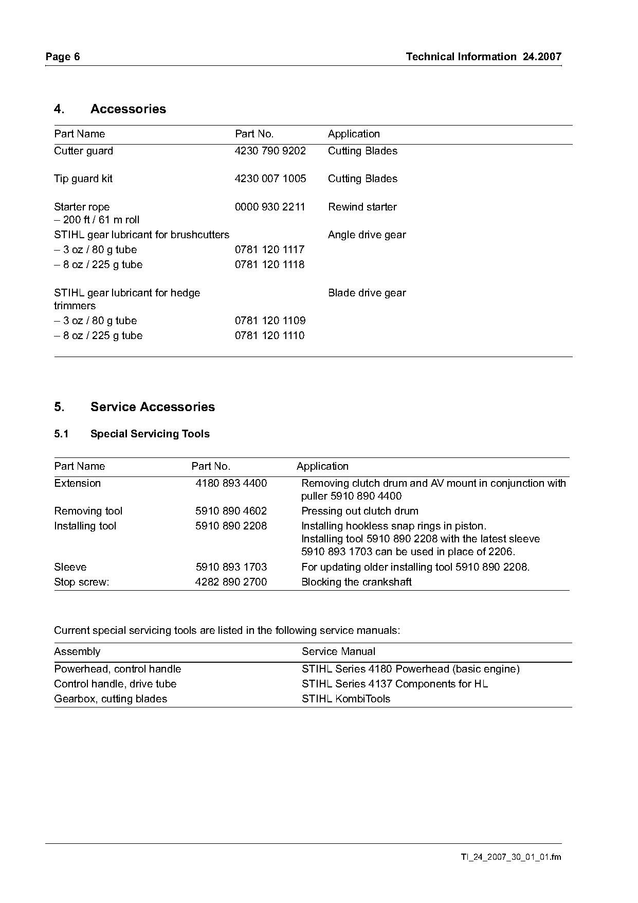
 4.      Accessories
 Part Name                                Part No.           Application
 Cutter guard                             4230 790 9202      Cutting Blades

 Tip guard kit                            4230 007 1005      Cutting Blades

 Starter rope                          0000 930 2211         Rewind starter
 – 200 ft / 61 m roll
 STIHL gear lubricant for brushcutters                       Angle drive gear
 – 3 oz / 80 g tube                    0781 120 1117
 – 8 oz / 225 g tube                   0781 120 1118

 STIHL gear lubricant for hedge                              Blade drive gear
 trimmers
 – 3 oz / 80 g tube                       0781 120 1109
 – 8 oz / 225 g tube                      0781 120 1110

 5.      Service Accessories

 5.1     Special Servicing Tools

 Part Name                     Part No.               Application
 Extension                      4180 893 4400          Removing clutch drum and AV mount in conjunction with
                                                       puller 5910 890 4400
 Removing tool                  5910 890 4602          Pressing out clutch drum
 Installing tool                5910 890 2208          Installing hookless snap rings in piston.
                                                       Installing tool 5910 890 2208 with the latest sleeve
                                                       5910 893 1703 can be used in place of 2206.
 Sleeve                         5910 893 1703          For updating older installing tool 5910 890 2208.
 Stop screw:                    4282 890 2700          Blocking the crankshaft

 Current special servicing tools are listed in the following service manuals:

 Assembly                                              Service Manual
 Powerhead, control handle                             STIHL Series 4180 Powerhead (basic engine)
 Control handle, drive tube                            STIHL Series 4137 Components for HL
 Gearbox, cutting blades                               STIHL KombiTools

                                                                                          TI_24_2007_30_01_01.fm
Page 7 of 8
Text of page 7 — search, copy, screen readers
Technical Information 24.2007                                                                               Page 7

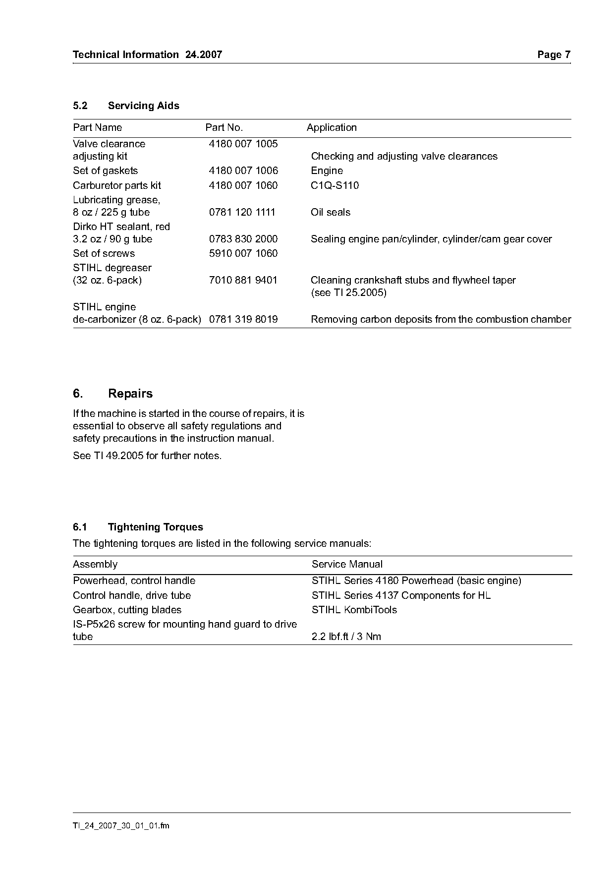
5.2     Servicing Aids

Part Name                       Part No.                    Application
Valve clearance                  4180 007 1005
adjusting kit                                               Checking and adjusting valve clearances
Set of gaskets                   4180 007 1006              Engine
Carburetor parts kit             4180 007 1060              C1Q-S110
Lubricating grease,
8 oz / 225 g tube                0781 120 1111              Oil seals
Dirko HT sealant, red
3.2 oz / 90 g tube               0783 830 2000              Sealing engine pan/cylinder, cylinder/cam gear cover
Set of screws                    5910 007 1060
STIHL degreaser
(32 oz. 6-pack)                  7010 881 9401              Cleaning crankshaft stubs and flywheel taper
                                                            (see TI 25.2005)
STIHL engine
de-carbonizer (8 oz. 6-pack) 0781 319 8019                  Removing carbon deposits from the combustion chamber

6.      Repairs
If the machine is started in the course of repairs, it is
essential to observe all safety regulations and
safety precautions in the instruction manual.
See TI 49.2005 for further notes.

6.1     Tightening Torques
The tightening torques are listed in the following service manuals:

Assembly                                                     Service Manual
Powerhead, control handle                                    STIHL Series 4180 Powerhead (basic engine)
Control handle, drive tube                                   STIHL Series 4137 Components for HL
Gearbox, cutting blades                                      STIHL KombiTools
IS-P5x26 screw for mounting hand guard to drive
tube                                                         2.2 lbf.ft / 3 Nm

TI_24_2007_30_01_01.fm
Page 8 of 8
Text of page 8 — search, copy, screen readers
Page 8                                                                     Technical Information 24.2007

6.2      Service Note
The following service manuals are available for servicing and repairs:

Assembly                                              Service Manual
Powerhead                                             STIHL Service Training System "Diagnosis"
Powerhead, control handle                             STIHL Series 4180 Powerhead (basic engine)
Control handle, drive tube                            STIHL Series 4137 Components for HL
Gearbox, cutting blades                               STIHL KombiTools

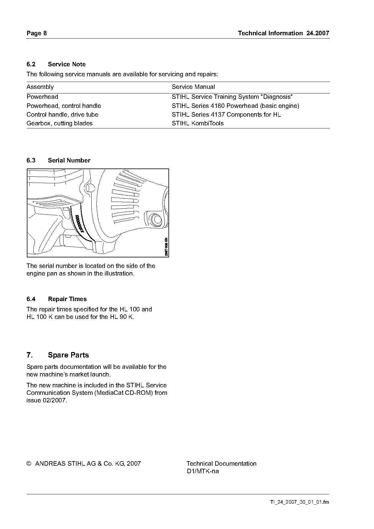
6.3      Serial Number

The serial number is located on the side of the
engine pan as shown in the illustration.

6.4      Repair Times
The repair times specified for the HL 100 and
HL 100 K can be used for the HL 90 K.

7.       Spare Parts
Spare parts documentation will be available for the
new machine’s market launch.
The new machine is included in the STIHL Service
Communication System                   from
issue 02/2007.

© ANDREAS STIHL AG & Co. KG, 2007                         Technical Documentation
                                                          D1/MTK-na

                                                                                      TI_24_2007_30_01_01.fm
Most of these PDFs embed fonts with a shifted character map, so the text above was recovered rather than copied — read it as a faithful but imperfect transcription, and treat the page image above each block as the authority where the two disagree — the figures exist only there, because they are vector drawings that text extraction cannot keep.