Technical Information · issue 37 of 2007
New cut-off machine STIHL TS 410, 420
IssueTI 37/2007
Full text
Page 1 of 16
Text of page 1 — search, copy, screen readers
STIH)

Technical Information                                   37.2007

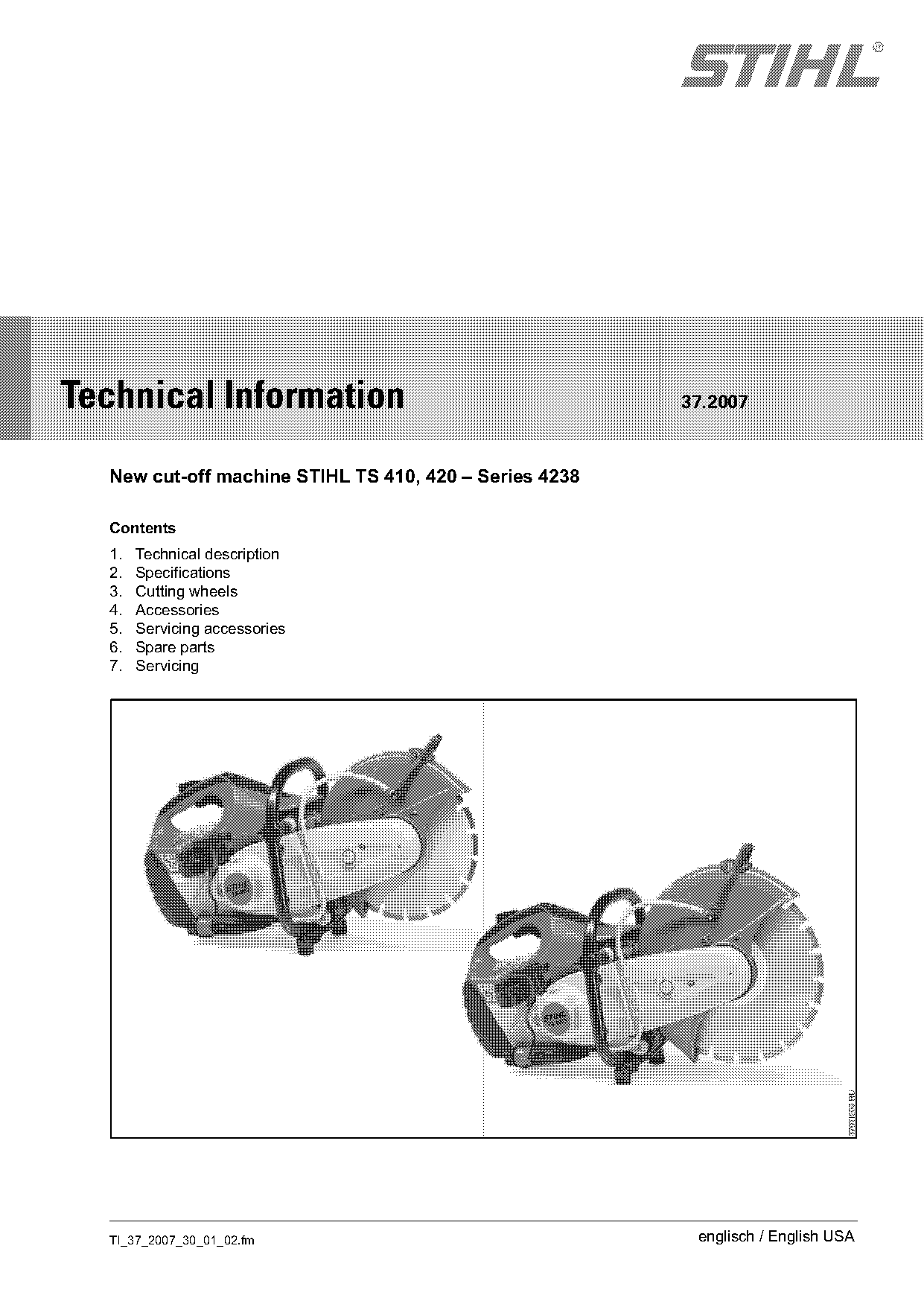
  New cut-off machine STIHL TS 410, 420 – Series 4238

  Contents
  1.   Technical description
  2.   Specifications
  3.   Cutting wheels
  4.   Accessories
  5.   Servicing accessories
  6.   Spare parts
  7.   Servicing

  TI_37_2007_30_01_02.fm                                 englisch / English USA
Page 2 of 16
Text of page 2 — search, copy, screen readers
Page 2                                                                        Technical Information 37.2007

The new cut-off machines STIHL TS 410 and                 The established long-life filter system with cyclone
TS 420 replaces the model TS 400. They are                pre-separation which is utilized on the TS 700 and
supplied in two versions (with mount for cutting          TS 800 has been further improved and sets
wheels measuring 12 in (300 mm) and 14 in                 revolutionary standards with regard to the filter life,
(350 mm) in diameter) ensuring that the most              which equals more than a year on average.
compact machine is available for the respective
                                                          The low-emission 2-cycle engine with stratified
applications.
                                                          scavenging not only conforms with present
Extended filter life, low-emission 2-cycle engine with    emission standards, but is also optimally prepared
stratified scavenging, effective anti-vibration system    for future regulations. In addition, the effective anti-
and light, compact design are characteristic              vibration system makes the TS 410 and TS 420 the
features of these powerful all-purpose machines.          cut-off machines with the lowest level of vibrations in
The machines can be used, for example, in the             the STIHL range.
building trade, by construction industry and rental       All operating functions are comfortably controlled by
firms, landscaping, by municipal authorities, public      conveniently arranged operating elements with
utilities, the construction materials and steel trades,   pictograms. In addition, the ergonomically designed
as well as by fire departments and emergency              wrap around handlebar allows the machine to be
rescue teams.                                             held in various positions.
The large variety of professional uses include free-      The newly developed magnesium guard can be
hand cutting of construction materials, precast           mounted inboard or outboard as required for the job
concrete parts, natural stone and pipes (concrete,        in hand. It is converted from one position to the
steel, ductile cast iron), as well as cutting asphalt     other in a matter of minutes.
and prefabricated parts in combination with a STIHL
Cutquik® cart.

                                                                                          TI_37_2007_30_01_02.fm
Page 3 of 16
Text of page 3 — search, copy, screen readers
Technical Information 37.2007                                                                          Page 3

1.        Technical description

1.1       Long-life air filter system with cyclone
          pre-separation

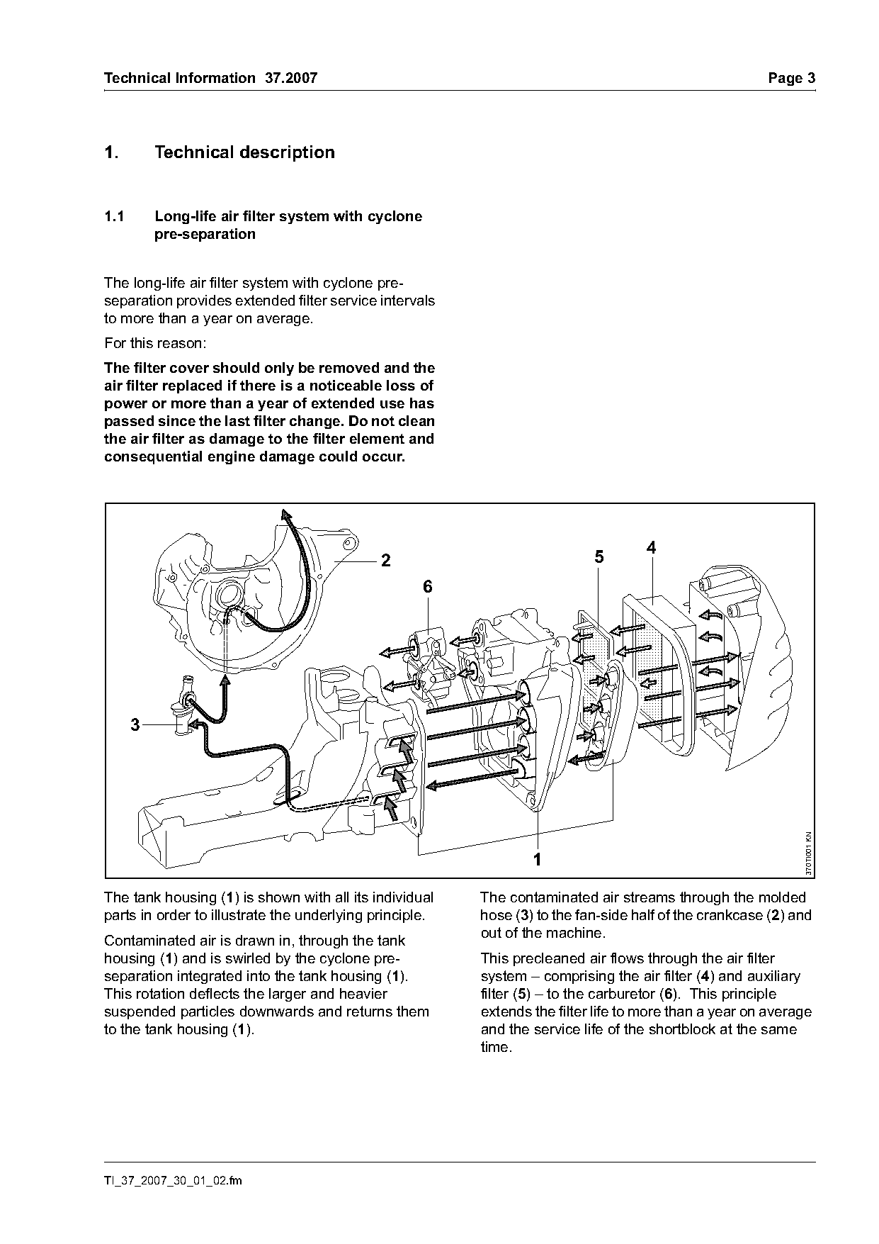
The long-life air filter system with cyclone pre-
separation provides extended filter service intervals
to more than a year on average.
For this reason:
The filter cover should only be removed and the
air filter replaced if there is a noticeable loss of
power or more than a year of extended use has
passed since the last filter change. Do not clean
the air filter as damage to the filter element and
consequential engine damage could occur.

                                                                                    4
                                             2                             5
                                                     6


                                                                                                             370TI001 KN


The tank housing (1) is shown with all its individual    The contaminated air streams through the molded
parts in order to illustrate the underlying principle.   hose (3) to the fan-side half of the crankcase (2) and
                                                         out of the machine.
Contaminated air is drawn in, through the tank
housing (1) and is swirled by the cyclone pre-           This precleaned air flows through the air filter
separation integrated into the tank housing (1).         system – comprising the air filter (4) and auxiliary
This rotation deflects the larger and heavier            filter (5) – to the carburetor (6). This principle
suspended particles downwards and returns them           extends the filter life to more than a year on average
to the tank housing (1).                                 and the service life of the shortblock at the same
                                                         time.

TI_37_2007_30_01_02.fm
Page 4 of 16
Text of page 4 — search, copy, screen readers
Page 4                                                                           Technical Information 37.2007

1.2      Principle of operation, stratified                  1.2.1   Mechanical design
         scavenging
A cushion of air (fuel-free) separates the unburned
fuel-air mixture from the exhaust gas. This cushion
of air is located in front of the fuel-air mixture. At the
start of the exhaust and scavenging cycle, fuel-free
air enters from the transfer ports into the combustion
chamber and scavenges the exhaust gas into the
exhaust port. The fuel-free air prevents the
unburned fuel-air mixture from entering the exhaust             4
port, thus reducing the environmental impact by
reducing scavenging losses and fuel consumption.
                                                                1


                                                                                                                  000TI043 KN
                                                                                               3

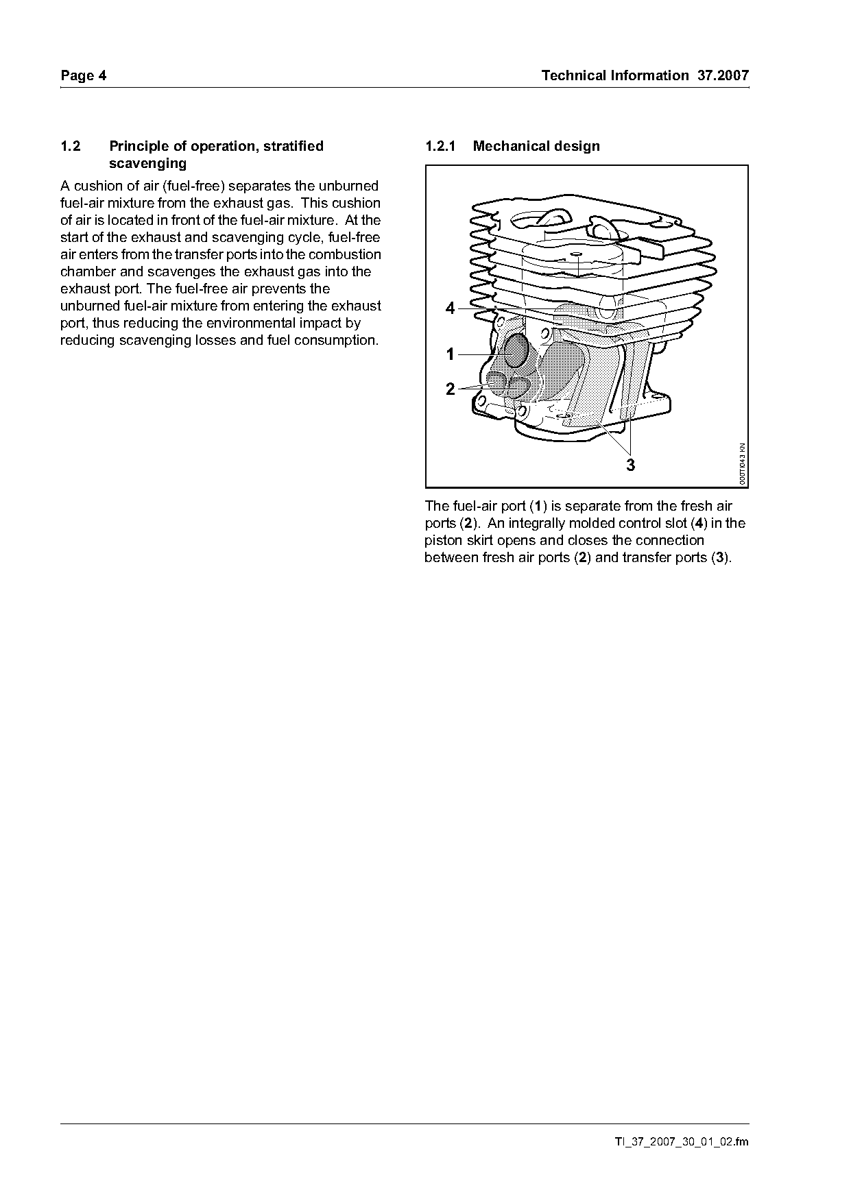
                                                             The fuel-air port (1) is separate from the fresh air
                                                             ports (2). An integrally molded control slot (4) in the
                                                             piston skirt opens and closes the connection
                                                             between fresh air ports (2) and transfer ports (3).

                                                                                             TI_37_2007_30_01_02.fm
Page 5 of 16
Text of page 5 — search, copy, screen readers
Technical Information 37.2007                                                                                   Page 5

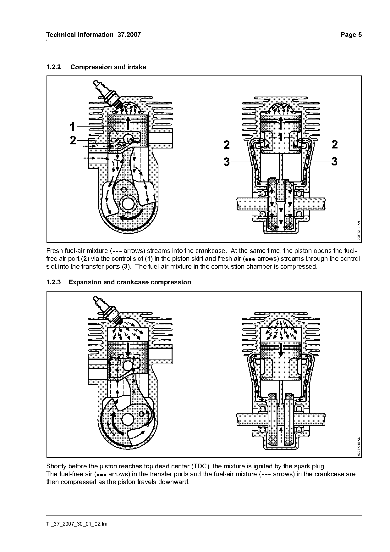
1.2.2    Compression and intake

        1
        2                                                                              1
                                                                   2                                        2
                                                                   3                                        3

                                                                                                                     000TI044 KN
Fresh fuel-air mixture (--- arrows) streams into the crankcase. At the same time, the piston opens the fuel-
free air port (2) via the control slot (1) in the piston skirt and fresh air (: : : arrows) streams through the control
slot into the transfer ports (3). The fuel-air mixture in the combustion chamber is compressed.

1.2.3   Expansion and crankcase compression

                                                                                                                     000TI045 KN

Shortly before the piston reaches top dead center (TDC), the mixture is ignited by the spark plug.
The fuel-free air (: :: arrows) in the transfer ports and the fuel-air mixture (--- arrows) in the crankcase are
then compressed as the piston travels downward.

TI_37_2007_30_01_02.fm
Page 6 of 16
Text of page 6 — search, copy, screen readers
Page 6                                                                     Technical Information 37.2007

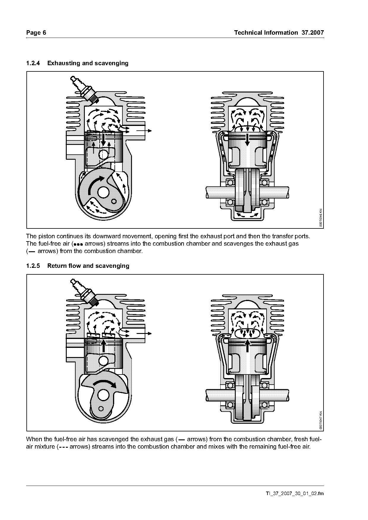
1.2.4    Exhausting and scavenging

                                                                                                          000TI046 KN
The piston continues its downward movement, opening first the exhaust port and then the transfer ports.
The fuel-free air (: :: arrows) streams into the combustion chamber and scavenges the exhaust gas
(--- arrows) from the combustion chamber.

1.2.5    Return flow and scavenging

                                                                                                          000TI047 KN

When the fuel-free air has scavenged the exhaust gas (--- arrows) from the combustion chamber, fresh fuel-
air mixture (--- arrows) streams into the combustion chamber and mixes with the remaining fuel-free air.

                                                                                      TI_37_2007_30_01_02.fm
Page 7 of 16
Text of page 7 — search, copy, screen readers
Technical Information 37.2007                                                                                      Page 7

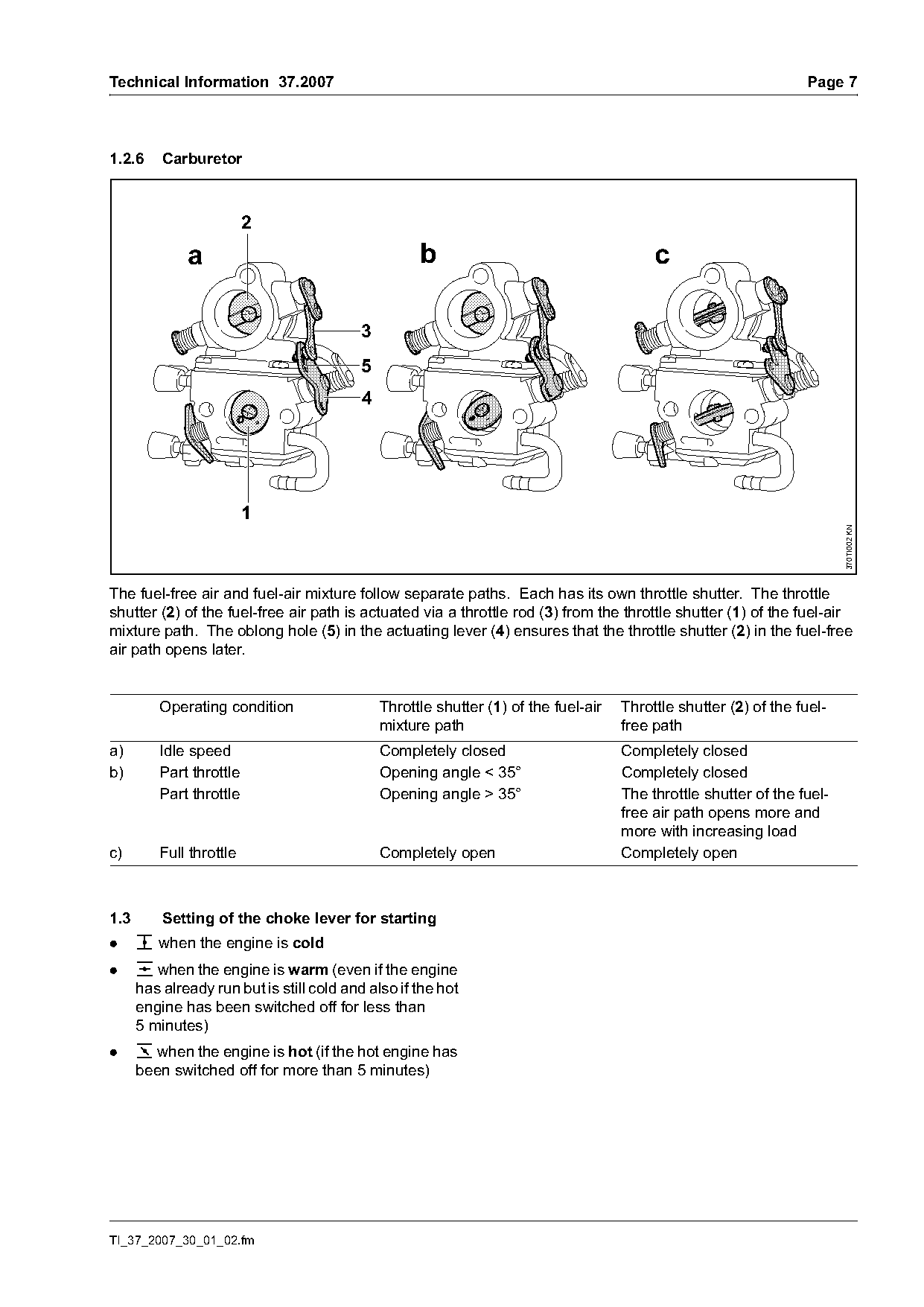
1.2.6     Carburetor

                         2
              a                                      b                                     c

                                           3
                                           5
                                           4


                                                                                                                          370TI002 KN
The fuel-free air and fuel-air mixture follow separate paths. Each has its own throttle shutter. The throttle
shutter (2) of the fuel-free air path is actuated via a throttle rod (3) from the throttle shutter (1) of the fuel-air
mixture path. The oblong hole (5) in the actuating lever (4) ensures that the throttle shutter (2) in the fuel-free
air path opens later.

         Operating condition                   Throttle shutter (1) of the fuel-air   Throttle shutter (2) of the fuel-
                                               mixture path                           free path
a)       Idle speed                            Completely closed                      Completely closed
b)       Part throttle                         Opening angle < 35°                    Completely closed
         Part throttle                         Opening angle > 35°                    The throttle shutter of the fuel-
                                                                                      free air path opens more and
                                                                                      more with increasing load
c)       Full throttle                         Completely open                        Completely open

1.3       Setting of the choke lever for starting
.     c when the engine is cold
.     e when the engine is warm (even if the engine
      has already run but is still cold and also if the hot
      engine has been switched off for less than
      5 minutes)
.     o when the engine is hot (if the hot engine has
      been switched off for more than 5 minutes)

TI_37_2007_30_01_02.fm
Page 8 of 16
Text of page 8 — search, copy, screen readers
Page 8                                                                 Technical Information 37.2007

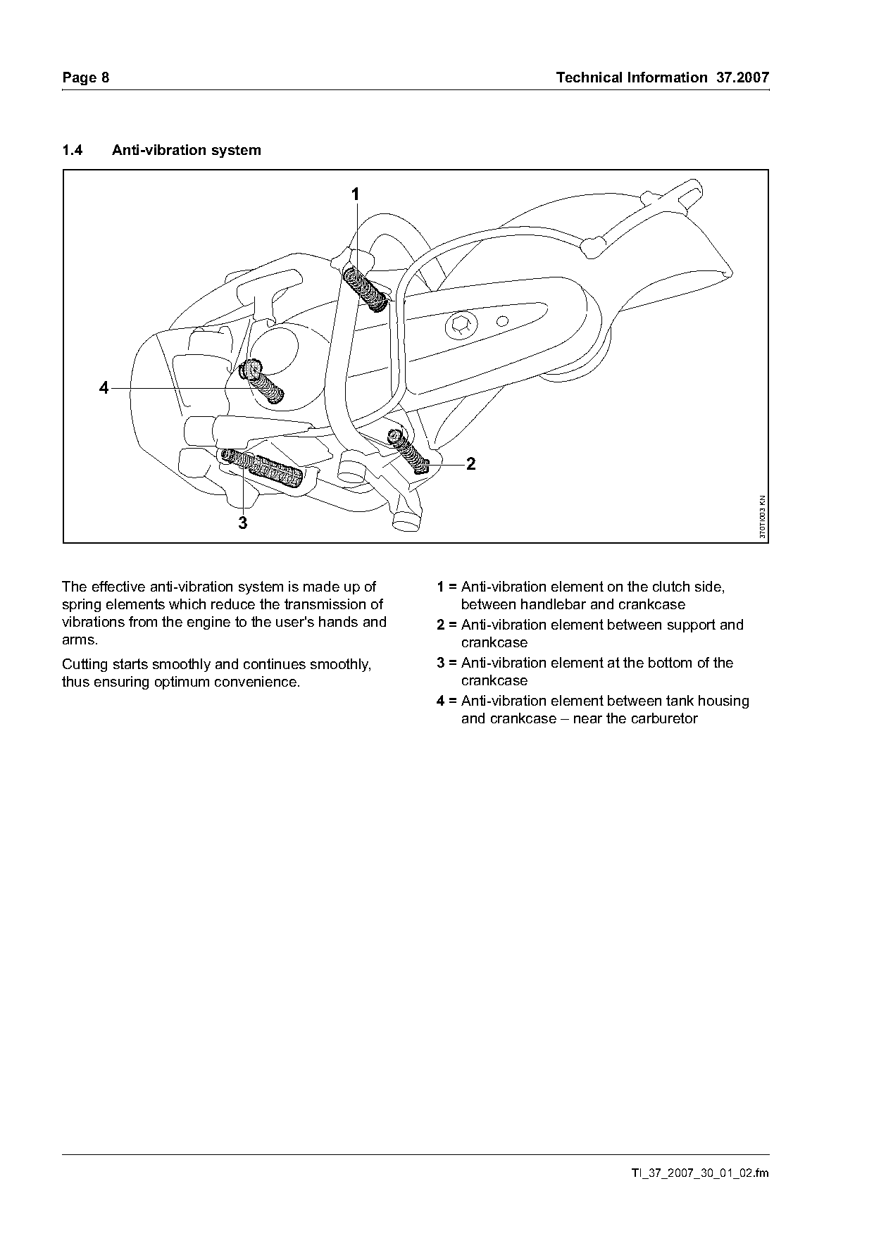
1.4       Anti-vibration system


                                                                                                       370TI003 KN
                           3

The effective anti-vibration system is made up of    1 = Anti-vibration element on the clutch side,
spring elements which reduce the transmission of         between handlebar and crankcase
vibrations from the engine to the user's hands and   2 = Anti-vibration element between support and
arms.                                                    crankcase
Cutting starts smoothly and continues smoothly,      3 = Anti-vibration element at the bottom of the
thus ensuring optimum convenience.                       crankcase
                                                     4 = Anti-vibration element between tank housing
                                                         and crankcase – near the carburetor

                                                                                  TI_37_2007_30_01_02.fm
Page 9 of 16
Text of page 9 — search, copy, screen readers
Technical Information 37.2007                                                                                 Page 9

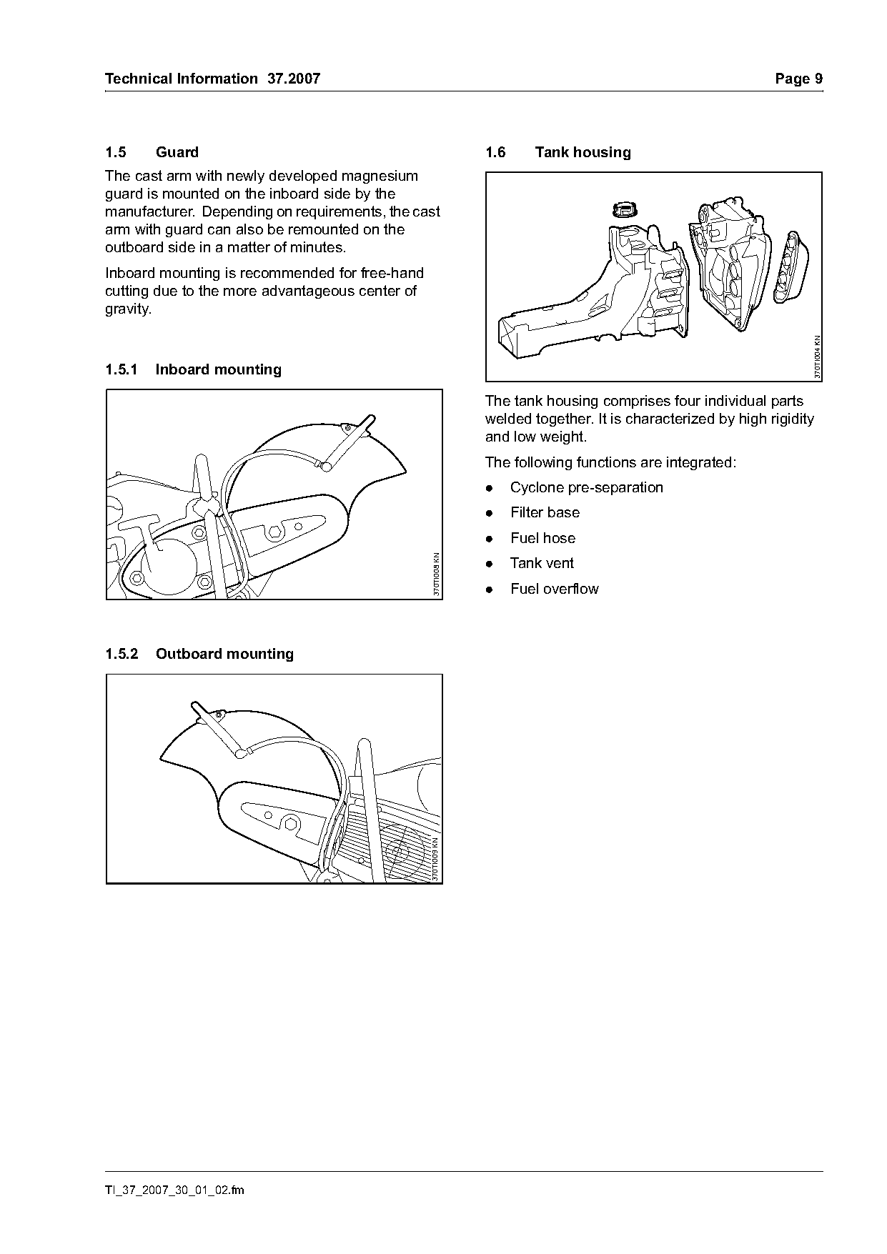
1.5     Guard                                                   1.6       Tank housing
The cast arm with newly developed magnesium
guard is mounted on the inboard side by the
manufacturer. Depending on requirements, the cast
arm with guard can also be remounted on the
outboard side in a matter of minutes.
Inboard mounting is recommended for free-hand
cutting due to the more advantageous center of
gravity.

                                                                                                                    370TI004 KN
1.5.1   Inboard mounting

                                                                The tank housing comprises four individual parts
                                                                welded together. It is characterized by high rigidity
                                                                and low weight.
                                                                The following functions are integrated:
                                                                .     Cyclone pre-separation
                                                                .     Filter base
                                                                .     Fuel hose
                                                  370TI008 KN

                                                                .     Tank vent
                                                                .     Fuel overflow

1.5.2   Outboard mounting
                                                 370TI009 KN

TI_37_2007_30_01_02.fm
Page 10 of 16
Text of page 10 — search, copy, screen readers
Page 10                                                                       Technical Information 37.2007

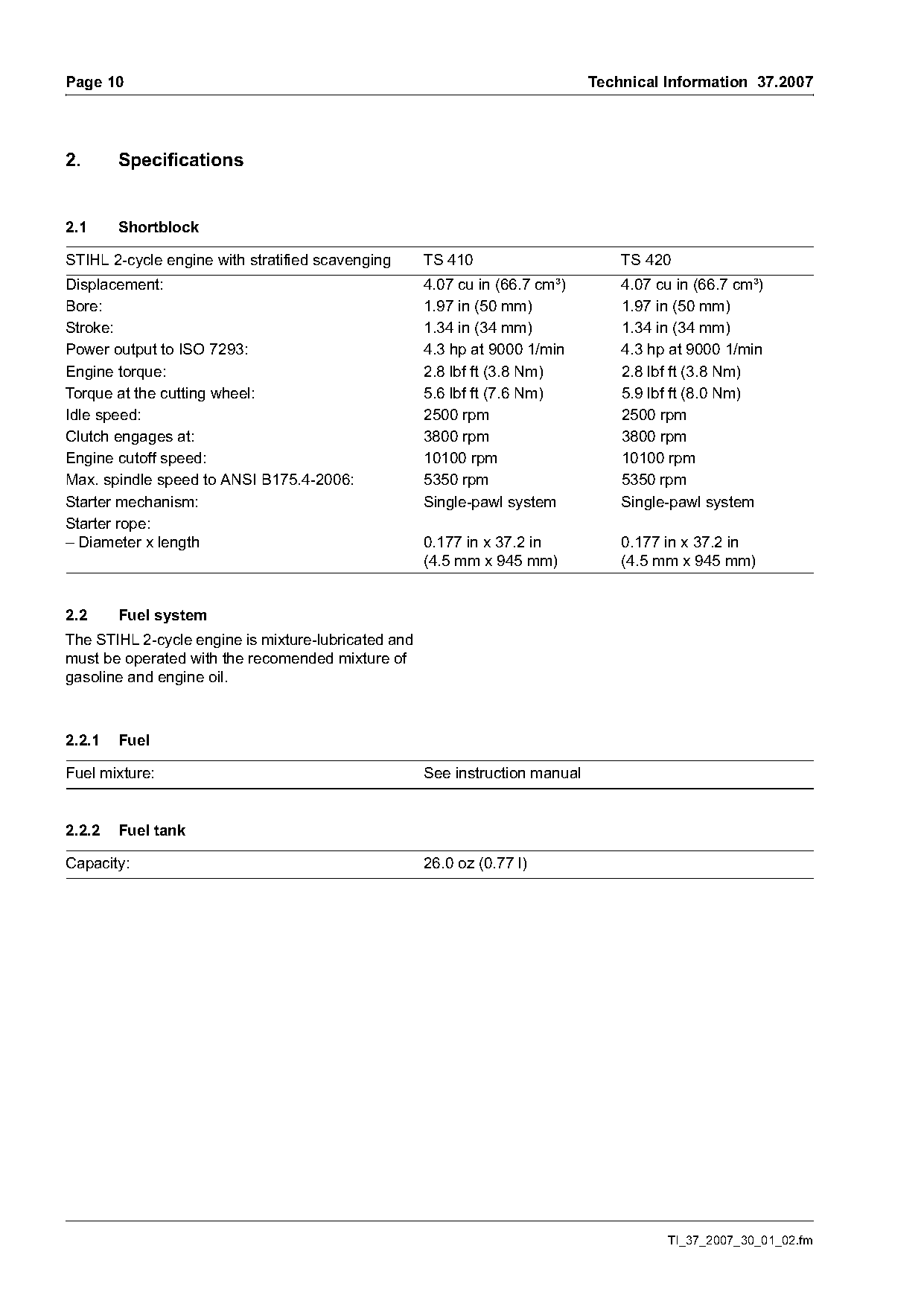
2.      Specifications

2.1     Shortblock

STIHL 2-cycle engine with stratified scavenging      TS 410                       TS 420
Displacement:                                        4.07 cu in (66.7 cm³)        4.07 cu in (66.7 cm³)
Bore:                                                1.97 in (50 mm)              1.97 in (50 mm)
Stroke:                                              1.34 in (34 mm)              1.34 in (34 mm)
Power output to ISO 7293:                            4.3 hp at 9000 1/min         4.3 hp at 9000 1/min
Engine torque:                                       2.8 lbf ft (3.8 Nm)          2.8 lbf ft (3.8 Nm)
Torque at the cutting wheel:                         5.6 lbf ft (7.6 Nm)          5.9 lbf ft (8.0 Nm)
Idle speed:                                          2500 rpm                     2500 rpm
Clutch engages at:                                   3800 rpm                     3800 rpm
Engine cutoff speed:                                 10100 rpm                    10100 rpm
Max. spindle speed to ANSI B175.4-2006:              5350 rpm                     5350 rpm
Starter mechanism:                                   Single-pawl system           Single-pawl system
Starter rope:
– Diameter x length                                  0.177 in x 37.2 in           0.177 in x 37.2 in
                                                     (4.5 mm x 945 mm)            (4.5 mm x 945 mm)

2.2     Fuel system
The STIHL 2-cycle engine is mixture-lubricated and
must be operated with the recomended mixture of
gasoline and engine oil.

2.2.1   Fuel

Fuel mixture:                                        See instruction manual

2.2.2   Fuel tank

Capacity:                                            26.0 oz (0.77 l)

                                                                                        TI_37_2007_30_01_02.fm
Page 11 of 16
Text of page 11 — search, copy, screen readers
Technical Information 37.2007                                                                         Page 11

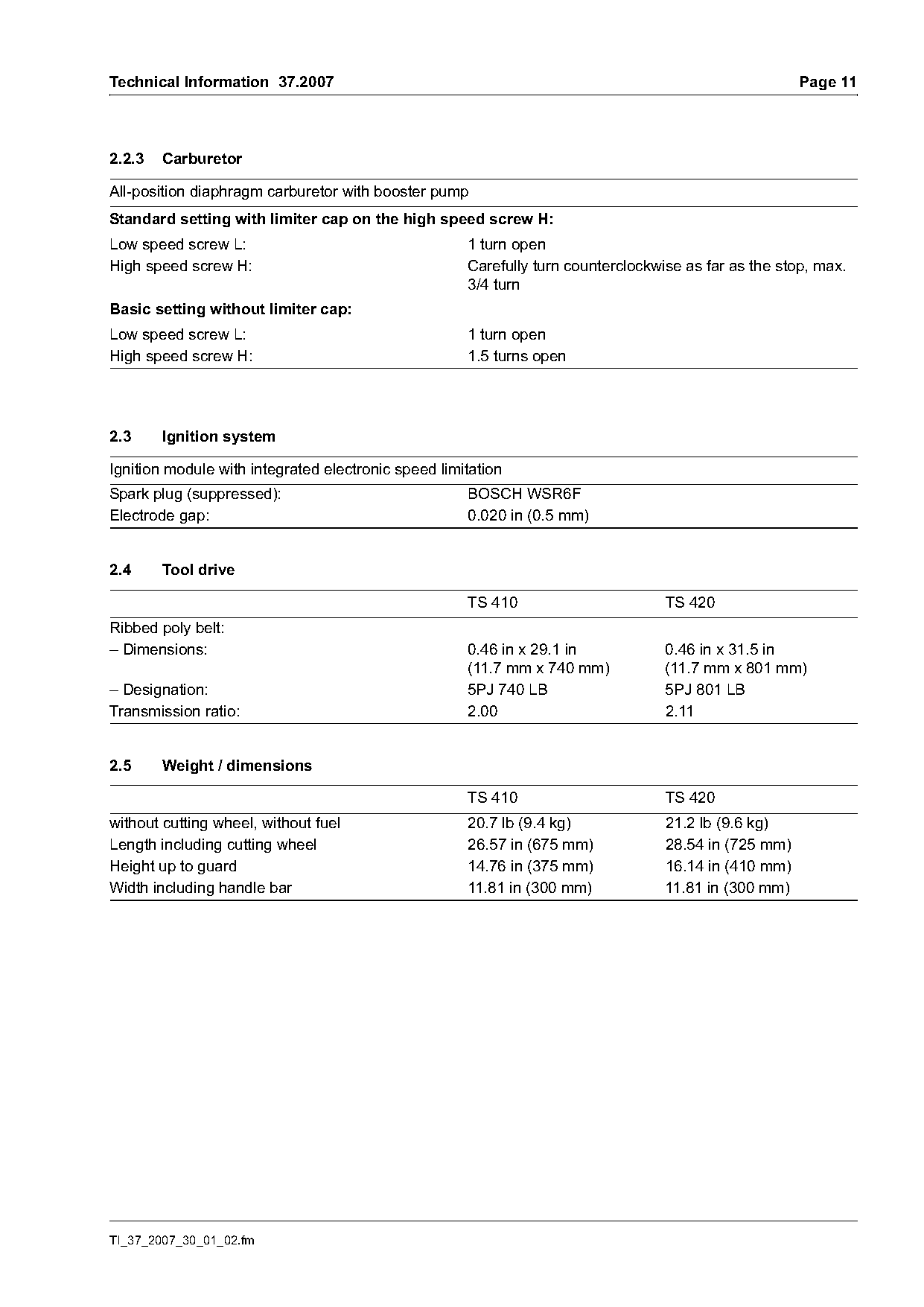
2.2.3   Carburetor

All-position diaphragm carburetor with booster pump
Standard setting with limiter cap on the high speed screw H:
Low speed screw L:                                   1 turn open
High speed screw H:                                  Carefully turn counterclockwise as far as the stop, max.
                                                     3/4 turn
Basic setting without limiter cap:
Low speed screw L:                                   1 turn open
High speed screw H:                                  1.5 turns open

2.3     Ignition system

Ignition module with integrated electronic speed limitation
Spark plug (suppressed):                             BOSCH WSR6F
Electrode gap:                                       0.020 in (0.5 mm)

2.4     Tool drive

                                                     TS 410                       TS 420
Ribbed poly belt:
– Dimensions:                                        0.46 in x 29.1 in            0.46 in x 31.5 in
                                                     (11.7 mm x 740 mm)           (11.7 mm x 801 mm)
– Designation:                                       5PJ 740 LB                   5PJ 801 LB
Transmission ratio:                                  2.00                         2.11

2.5     Weight / dimensions

                                                     TS 410                       TS 420
without cutting wheel, without fuel                  20.7 lb (9.4 kg)             21.2 lb (9.6 kg)
Length including cutting wheel                       26.57 in (675 mm)            28.54 in (725 mm)
Height up to guard                                   14.76 in (375 mm)            16.14 in (410 mm)
Width including handle bar                           11.81 in (300 mm)            11.81 in (300 mm)

TI_37_2007_30_01_02.fm
Page 12 of 16
Text of page 12 — search, copy, screen readers
Page 12                                                                       Technical Information 37.2007

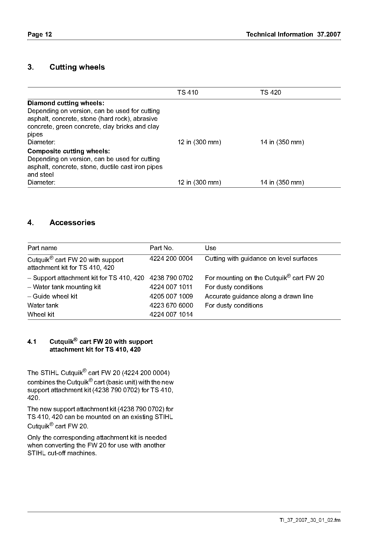
3.     Cutting wheels

                                                       TS 410                      TS 420
Diamond cutting wheels:
Depending on version, can be used for cutting
asphalt, concrete, stone (hard rock), abrasive
concrete, green concrete, clay bricks and clay
pipes
Diameter:                                              12 in (300 mm)              14 in (350 mm)
Composite cutting wheels:
Depending on version, can be used for cutting
asphalt, concrete, stone, ductile cast iron pipes
and steel
Diameter:                                              12 in (300 mm)              14 in (350 mm)

4.      Accessories

Part name                                   Part No.            Use
Cutquik® cart FW 20 with support            4224 200 0004       Cutting with guidance on level surfaces
attachment kit for TS 410, 420
– Support attachment kit for TS 410, 420    4238 790 0702       For mounting on the Cutquik® cart FW 20
– Water tank mounting kit                   4224 007 1011       For dusty conditions
– Guide wheel kit                           4205 007 1009       Accurate guidance along a drawn line
Water tank                                  4223 670 6000       For dusty conditions
Wheel kit                                   4224 007 1014

4.1     Cutquik® cart FW 20 with support
        attachment kit for TS 410, 420

The STIHL Cutquik® cart FW 20 (4224 200 0004)
combines the Cutquik® cart (basic unit) with the new
support attachment kit (4238 790 0702) for TS 410,
420.
The new support attachment kit (4238 790 0702) for
TS 410, 420 can be mounted on an existing STIHL
Cutquik® cart FW 20.
Only the corresponding attachment kit is needed
when converting the FW 20 for use with another
STIHL cut-off machines.

                                                                                         TI_37_2007_30_01_02.fm
Page 13 of 16
Text of page 13 — search, copy, screen readers
Technical Information 37.2007                                                                 Page 13

5.      Servicing accessories

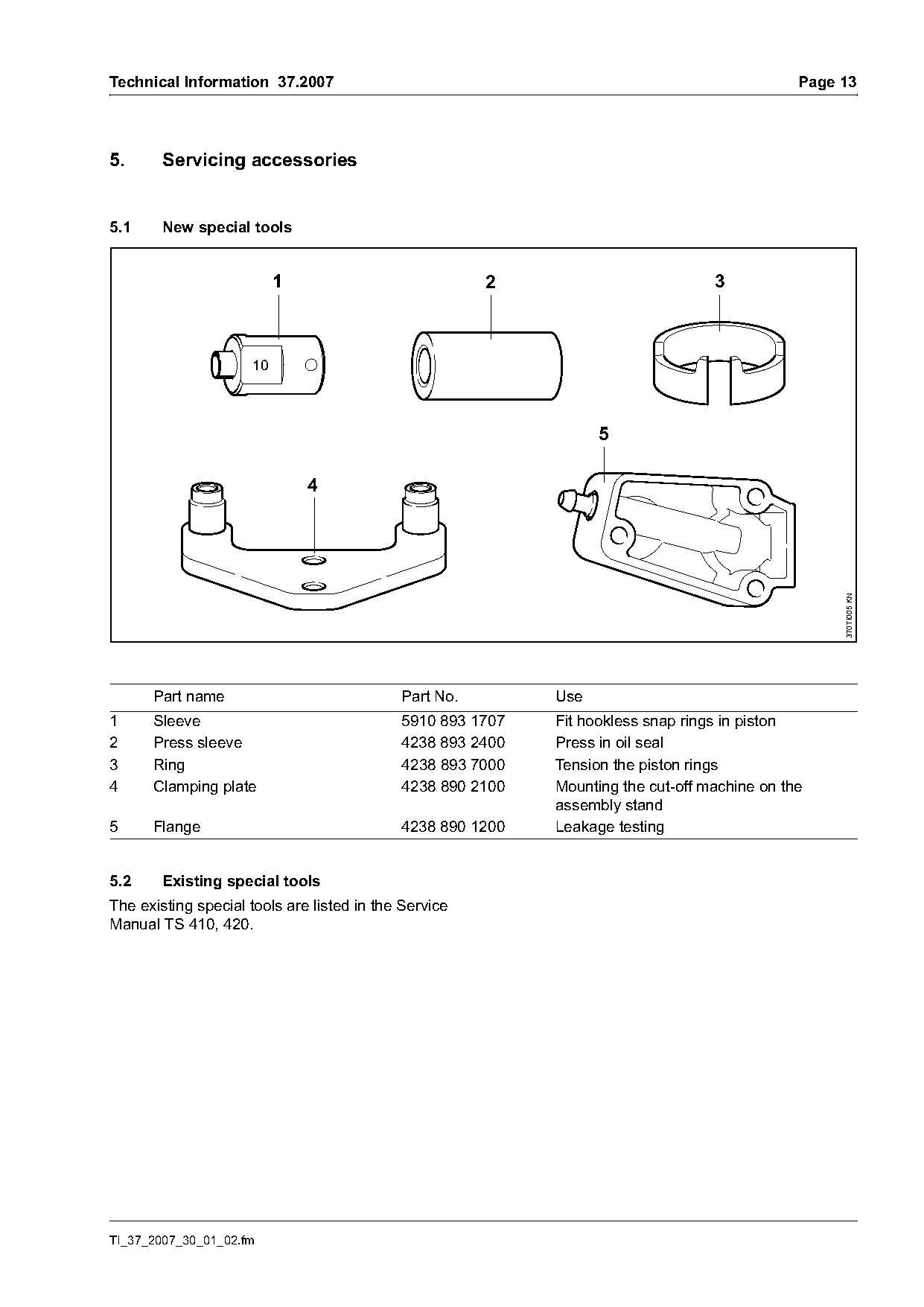
5.1     New special tools

                          1                            2                          3


                                                                                                   370TI005 KN
      Part name                             Part No.        Use
1     Sleeve                                5910 893 1707   Fit hookless snap rings in piston
2     Press sleeve                          4238 893 2400   Press in oil seal
3     Ring                                  4238 893 7000   Tension the piston rings
4     Clamping plate                        4238 890 2100   Mounting the cut-off machine on the
                                                            assembly stand
5     Flange                                4238 890 1200   Leakage testing

5.2     Existing special tools
The existing special tools are listed in the Service
Manual TS 410, 420.

TI_37_2007_30_01_02.fm
Page 14 of 16
Text of page 14 — search, copy, screen readers
Page 14                                                                  Technical Information 37.2007

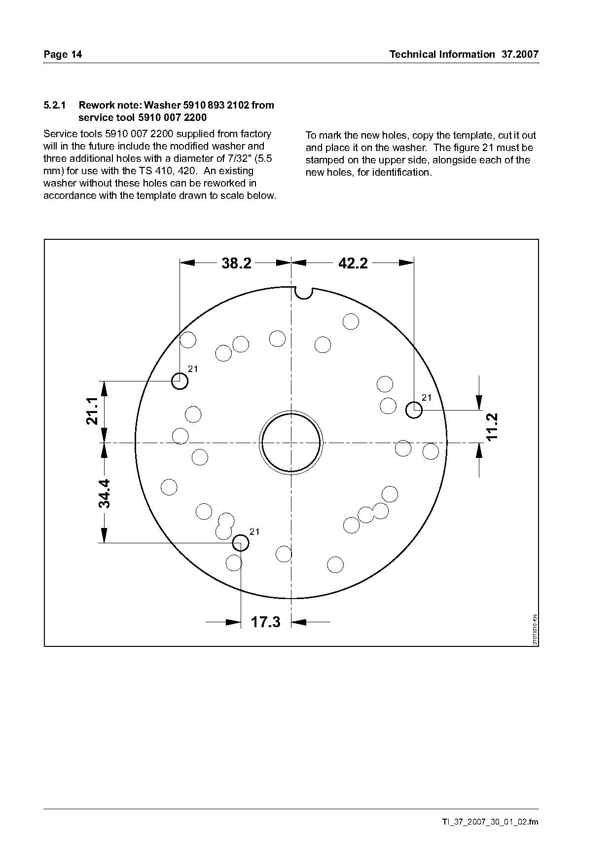
5.2.1   Rework note: Washer 5910 893 2102 from
        service tool 5910 007 2200
Service tools 5910 007 2200 supplied from factory      To mark the new holes, copy the template, cut it out
will in the future include the modified washer and     and place it on the washer. The figure 21 must be
three additional holes with a diameter of 7/32" (5.5   stamped on the upper side, alongside each of the
mm) for use with the TS 410, 420. An existing          new holes, for identification.
washer without these holes can be reworked in
accordance with the template drawn to scale below.

                                       38.2                   42.2


                                                                                 21
          21.1

                                                                                               11.2
            34.4


                                              17.3
                                                                                                          370TI010 KN

                                                                                      TI_37_2007_30_01_02.fm
Page 15 of 16
Text of page 15 — search, copy, screen readers
Technical Information 37.2007                                                                           Page 15

5.3     Servicing accessories

Part name                                   Part No.                  Use
Set of gaskets                              4238 007 1003             Shortblock
Set of carburetor parts                     4238 007 1060             Carburetor C1Q-S118
Lubricating grease (225 g tube)             0781 120 1111             Oil seals, sliding and bearing points
STIHL special lubricant                     0781 417 1315             Bearing bore in the rope rotor, rewind
                                                                      spring in the starter cover
Press Fluid OH 723                          0781 957 9000
STIHL multi-purpose grease                  0781 120 1109
Tube of sealant Dirko HT red                0783 830 2000             Engine pan, oil seals (outside)
Loctite 242                                 0786 111 2101
Loctite 270                                 0786 111 2109
Loctite 648                                 0786 111 2117
Standard solvent-based degreasant not                                 Cleaning the mating faces and
containing any chlorinated or                                         carburetor, crankshaft stub and cone in
halogenated hydrocarbons                                              flywheel

6.      Spare parts
The spare parts lists for TS 410, 420 will be
available when the machines are launched on the
market.
The new machines are included in the STIHL
Service Communication System (SCS /                ) from edition 03/2007 onwards.

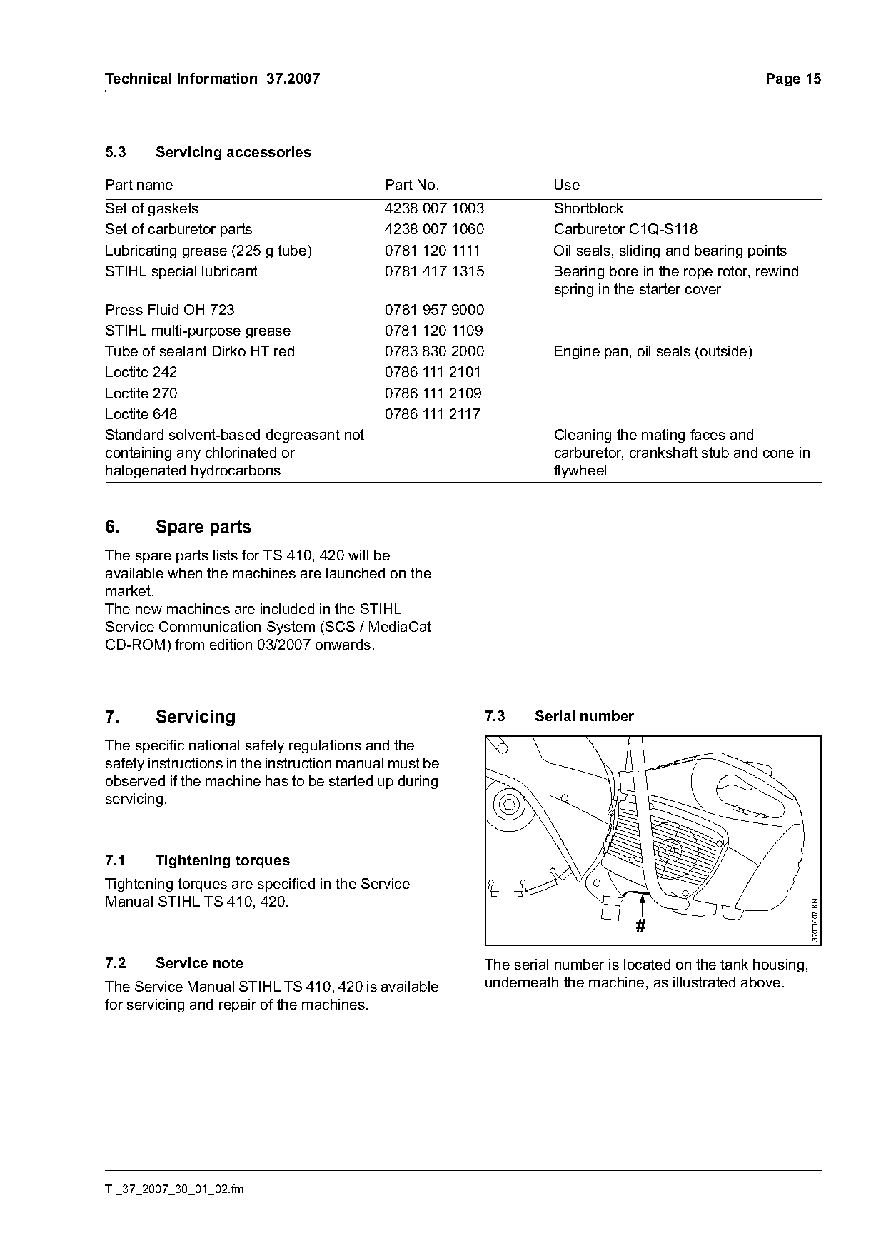
7.      Servicing                                           7.3    Serial number

The specific national safety regulations and the
safety instructions in the instruction manual must be
observed if the machine has to be started up during
servicing.

7.1     Tightening torques
Tightening torques are specified in the Service
Manual STIHL TS 410, 420.
                                                                                                                370TI007 KN

                                                                                   #

7.2     Service note                                        The serial number is located on the tank housing,
The Service Manual STIHL TS 410, 420 is available           underneath the machine, as illustrated above.
for servicing and repair of the machines.

TI_37_2007_30_01_02.fm
Page 16 of 16
Text of page 16 — search, copy, screen readers
Page 16                                                                  Technical Information 37.2007

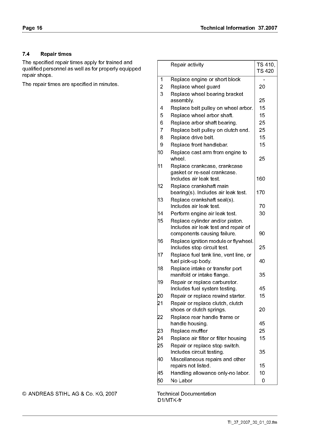
7.4    Repair times
The specified repair times apply for trained and            Repair activity                      TS 410,
qualified personnel as well as for properly equipped                                             TS 420
repair shops.
                                                        1   Replace engine or short block           -
The repair times are specified in minutes.
                                                        2   Replace wheel guard                    20
                                                        3   Replace wheel bearing bracket
                                                            assembly.                              25
                                                        4   Replace belt pulley on wheel arbor. 15
                                                        5   Replace wheel arbor shaft.             15
                                                        6   Replace arbor shaft bearing.           25
                                                        7   Replace belt pulley on clutch end.     25
                                                        8   Replace drive belt.                    15
                                                        9   Replace front handlebar.               15
                                                       10   Replace cast arm from engine to
                                                            wheel.                                 25
                                                       11   Replace crankcase, crankcase
                                                            gasket or re-seal crankcase.
                                                            Includes air leak test.               160
                                                       12   Replace crankshaft main
                                                            bearing(s). Includes air leak test.   170
                                                       13   Replace crankshaft seal(s).
                                                            Includes air leak test.                70
                                                       14   Perform engine air leak test.          30
                                                       15   Replace cylinder and/or piston.
                                                            Includes air leak test and repair of
                                                            components causing failure.            90
                                                       16   Replace ignition module or flywheel.
                                                            Includes stop circuit test.            25
                                                       17   Replace fuel tank line, vent line, or
                                                            fuel pick-up body.                     40
                                                       18   Replace intake or transfer port
                                                            manifold or intake flange.             35
                                                       19   Repair or replace carburetor.
                                                            Includes fuel system testing.          45
                                                       20   Repair or replace rewind starter.      15
                                                       21   Repair or replace clutch, clutch
                                                            shoes or clutch springs.               20
                                                       22   Replace rear handle frame or
                                                            handle housing.                        45
                                                       23   Replace muffler                        25
                                                       24   Replace air filter or filter housing   15
                                                       25   Repair or replace stop switch.
                                                            Includes circuit testing.              35
                                                       40   Miscellaneous repairs and other
                                                            repairs not listed.                    15
                                                       45   Handling allowance only-no labor.      10
                                                       50   No Labor                                0

© ANDREAS STIHL AG & Co. KG, 2007                      Technical Documentation
                                                       D1/MTK-fr

                                                                                    TI_37_2007_30_01_02.fm
Most of these PDFs embed fonts with a shifted character map, so the text above was recovered rather than copied — read it as a faithful but imperfect transcription, and treat the page image above each block as the authority where the two disagree — the figures exist only there, because they are vector drawings that text extraction cannot keep.