Technical Information · issue 42 of 2007
Telescoping Drive Tube Assembly; Assembly Instructions; Parts of Drive Tube; Repairs; Summary
IssueTI 42/2007
Part changes (1)
| Was | Becomes | What the bulletin says |
|---|---|---|
| 4138 710 7103 | 4182 710 7110 | Telescoping Drive Tube Assembly 1 2 Drive tube assembly 4138 710 7103 has been 3 4 replaced by version 4182 710 7110, which was previously introduced for the HT 131 pole pruner. |
Full text
Page 1 of 3
Text of page 1 — search, copy, screen readers
STIH)

Technical Information                                                              42.2007

  STIHL HT 75 Pole Pruner – Series 4138

  Contents
  1. Telescoping Drive Tube Assembly
     1.1 Assembly Instructions
     1.2 Parts of Drive Tube
  2. Repairs
  3. Summary

  1.     Telescoping Drive Tube Assembly
                                                                           1       2
  Drive tube assembly 4138 710 7103 has been                               3       4
  replaced by version 4182 710 7110, which was
  previously introduced for the HT 131 pole pruner.

  1.1     Assembly Instructions
  HT 75 pole pruners shipped from the factory are not
  completely assembled. The gearbox has to be
  installed.                                                                                                 246TI001 KN

  Warning! The drive tube assembly and gearbox
  must be properly installed before the engine may be
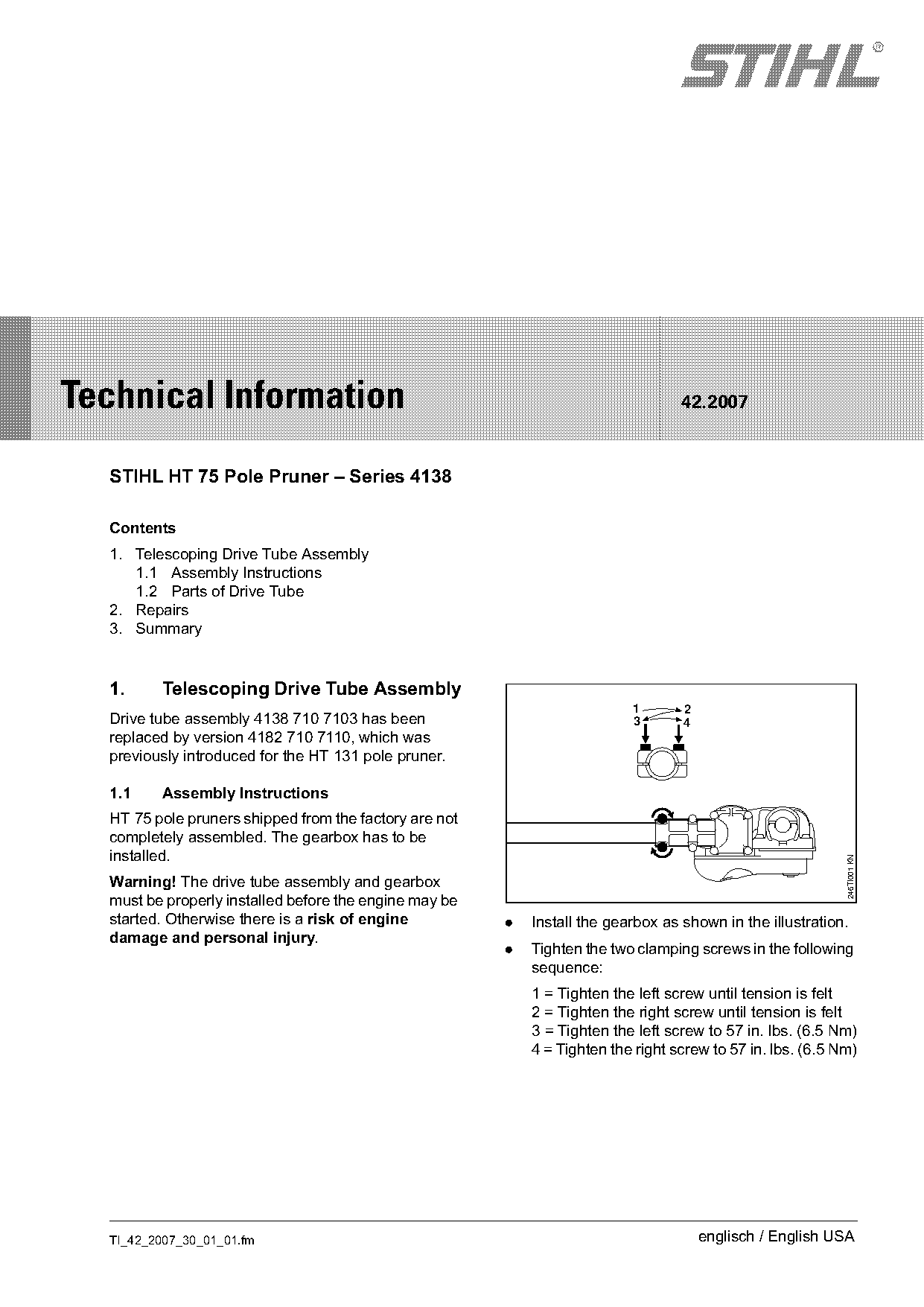
  started. Otherwise there is a risk of engine          .   Install the gearbox as shown in the illustration.
  damage and personal injury.
                                                        .   Tighten the two clamping screws in the following
                                                            sequence:
                                                            1 = Tighten the left screw until tension is felt
                                                            2 = Tighten the right screw until tension is felt
                                                            3 = Tighten the left screw to 57 in. lbs. (6.5 Nm)
                                                            4 = Tighten the right screw to 57 in. lbs. (6.5 Nm)

  TI_42_2007_30_01_01.fm                                                               englisch / English USA
Page 2 of 3
Text of page 2 — search, copy, screen readers
Page 2                                                                               Technical Information 42.2007

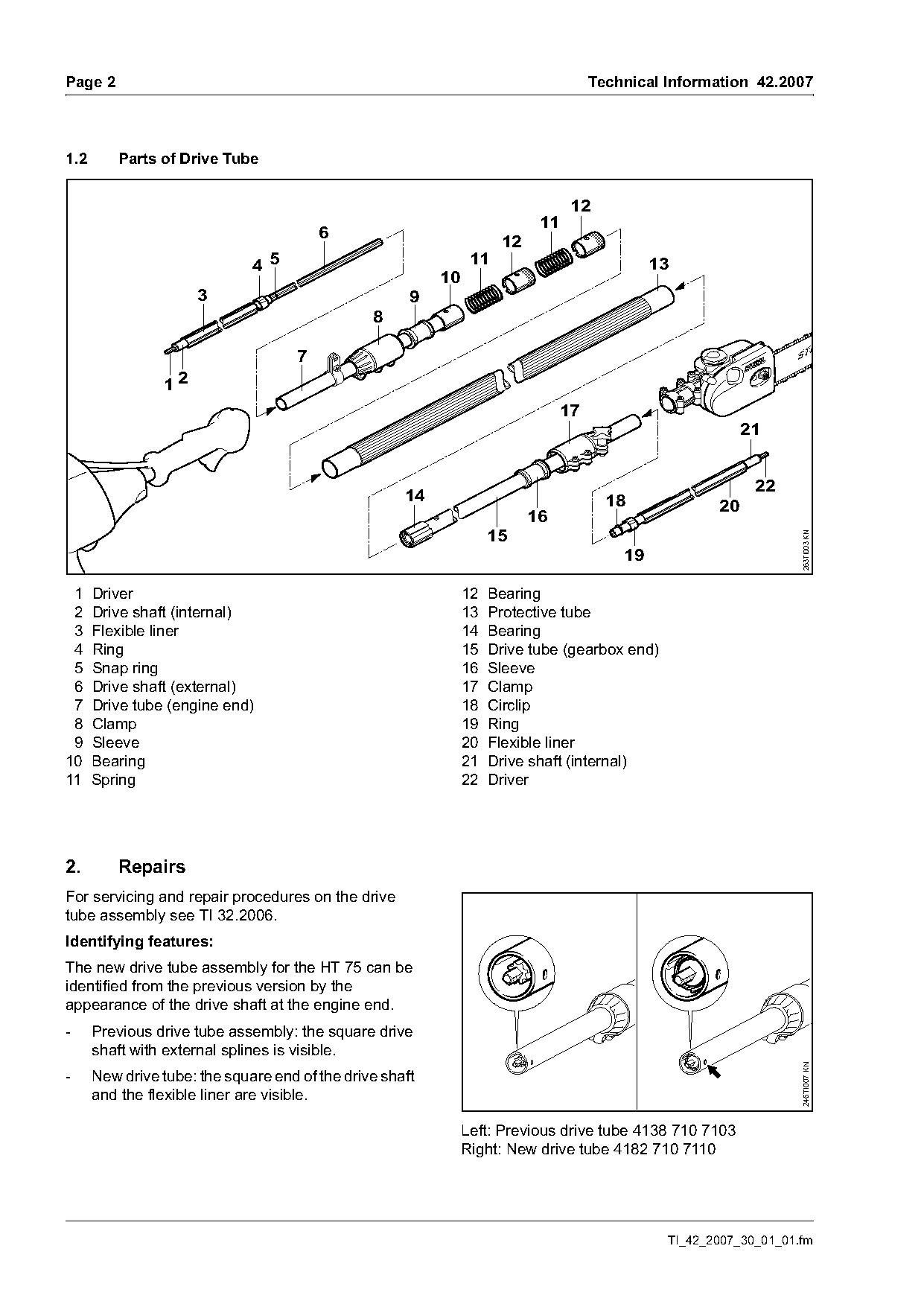
1.2      Parts of Drive Tube

                                                                                 12
                                                                           11
                                         6
                                                                     12
                              4 5                               11                            13
                                                          10
                     3                                9
                                                8

                                     7
                12
                                                                                17
                                                                                                           21

                                                                                                            22
                                                     14                                18             20
                                                                          16
                                                                  15

                                                                                                                   263TI003 KN
                                                                                         19

 1 Driver                                                      12 Bearing
 2 Drive shaft (internal)                                      13 Protective tube
 3 Flexible liner                                              14 Bearing
 4 Ring                                                        15 Drive tube (gearbox end)
 5 Snap ring                                                   16 Sleeve
 6 Drive shaft (external)                                      17 Clamp
 7 Drive tube (engine end)                                     18 Circlip
 8 Clamp                                                       19 Ring
 9 Sleeve                                                      20 Flexible liner
10 Bearing                                                     21 Drive shaft (internal)
11 Spring                                                      22 Driver

2.       Repairs
For servicing and repair procedures on the drive
tube assembly see TI 32.2006.
Identifying features:
The new drive tube assembly for the HT 75 can be
identified from the previous version by the
appearance of the drive shaft at the engine end.
-     Previous drive tube assembly: the square drive
      shaft with external splines is visible.
                                                                                                                   246TI007 KN

-     New drive tube: the square end of the drive shaft
      and the flexible liner are visible.

                                                               Left: Previous drive tube 4138 710 7103
                                                               Right: New drive tube 4182 710 7110

                                                                                               TI_42_2007_30_01_01.fm
Page 3 of 3
Text of page 3 — search, copy, screen readers
Technical Information 42.2007                                                                Page 3

The previous drive tube assembly for the HT 75
requires an alignment hole for installation into the
engine. For this reason the new drive tube assembly
for the HT 131 will also incorporate an installation
hole (see arrow in illustration).

3.     Summary
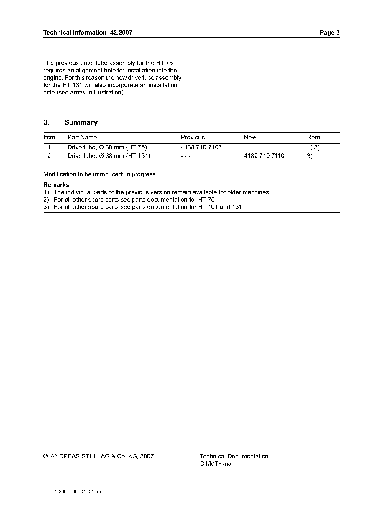
Item     Part Name                                 Previous              New             Rem.
 1       Drive tube, Ø 38 mm (HT 75)               4138 710 7103         ---             1) 2)
 2       Drive tube, Ø 38 mm (HT 131)              ---                   4182 710 7110   3)

Modification to be introduced: in progress
Remarks
1) The individual parts of the previous version remain available for older machines
2) For all other spare parts see parts documentation for HT 75
3) For all other spare parts see parts documentation for HT 101 and 131

© ANDREAS STIHL AG & Co. KG, 2007                        Technical Documentation
                                                         D1/MTK-na

TI_42_2007_30_01_01.fm
Most of these PDFs embed fonts with a shifted character map, so the text above was recovered rather than copied — read it as a faithful but imperfect transcription, and treat the page image above each block as the authority where the two disagree — the figures exist only there, because they are vector drawings that text extraction cannot keep.