Technical Information · issue 43 of 2007
Introduction; Support with guard; Starter cover; Cylinder with piston; Carburetor; Tank housing, crankcase, fan side; Permissible combinations
IssueTI 43/2007
Part changes (12)
| Was | Becomes | What the bulletin says |
|---|---|---|
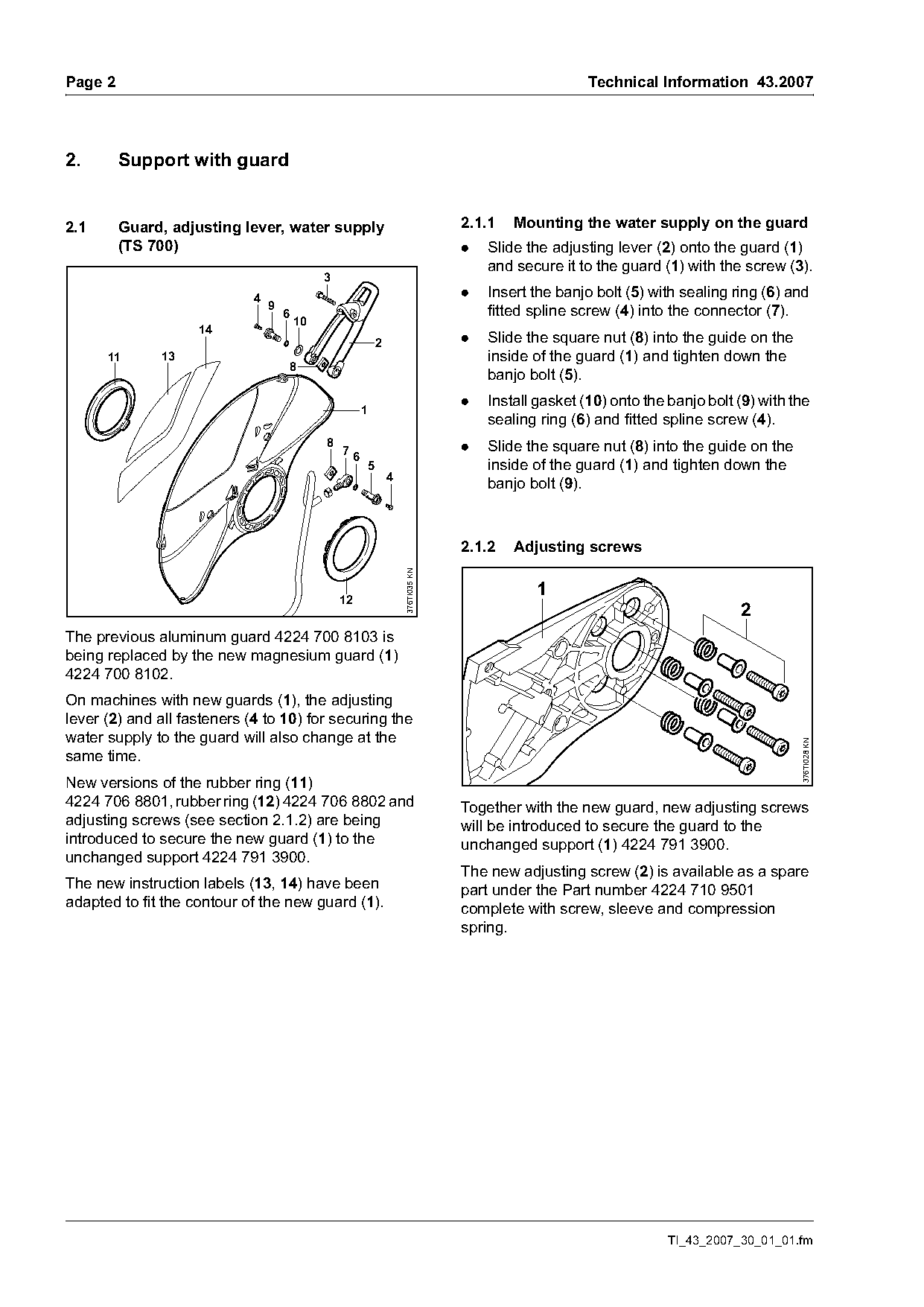
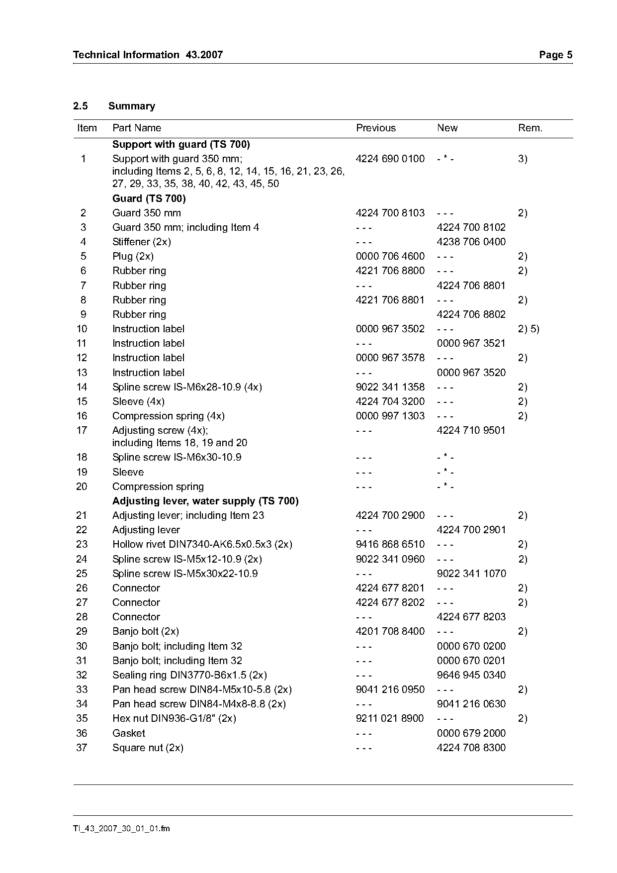
| 4224 700 8103 | 4224 700 8102 | 12 1 2 The previous aluminum guard 4224 700 8103 is being replaced by the new magnesium guard (1) 4224 700 8102. |
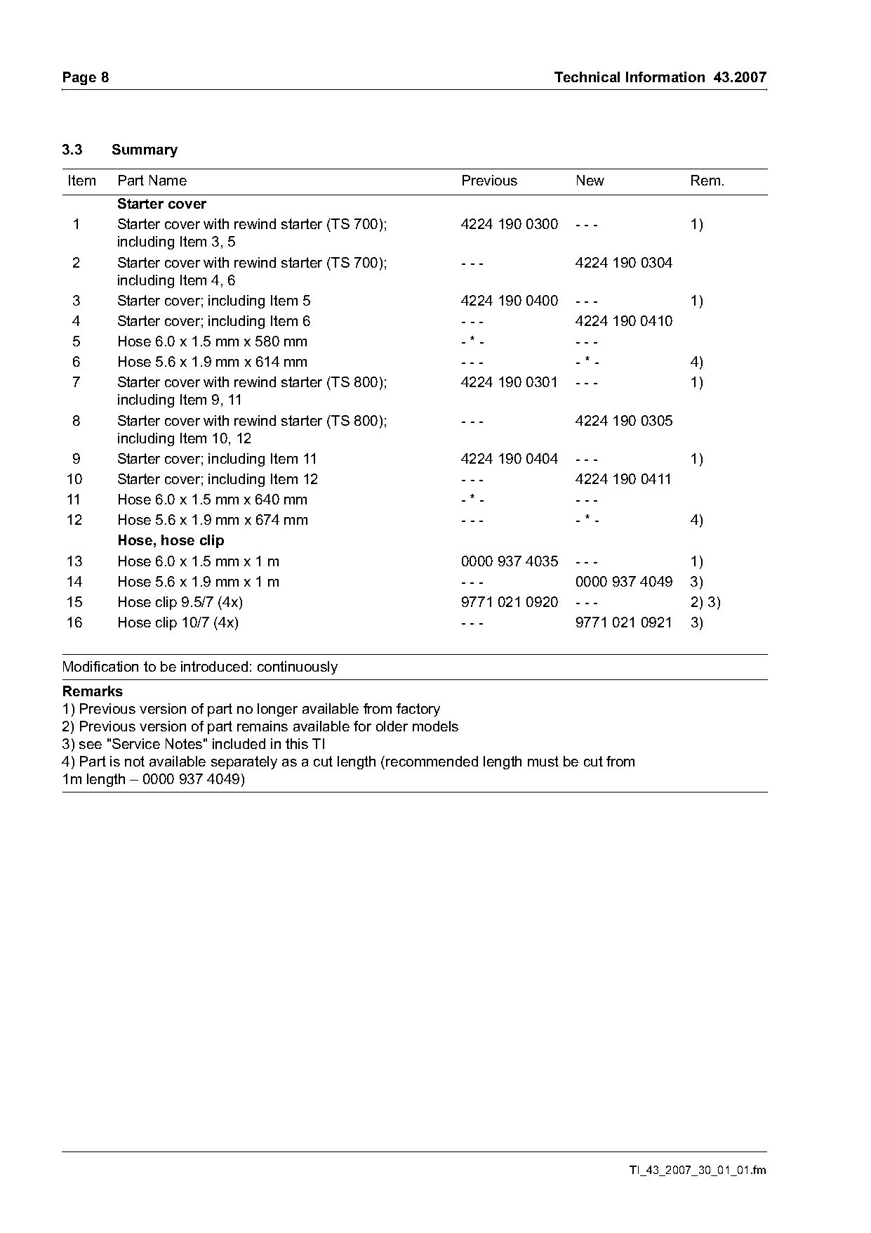
| 9771 021 0920 | 9771 021 0921 | Due to the larger outside diameter of the new hose, the previous version of the hose clip 9771 021 0920 will be replaced by a larger version 9771 021 0921. |
| 4224 020 1202 | 4224 020 1205 | 1 Introduction To further enhance the running behavior, the A new "cylinder with piston" will be introduced in two previous "cylinder with piston" 4224 020 1202 will stages to improve the running behavior: be replaced by the new version 4224 020 1205. |
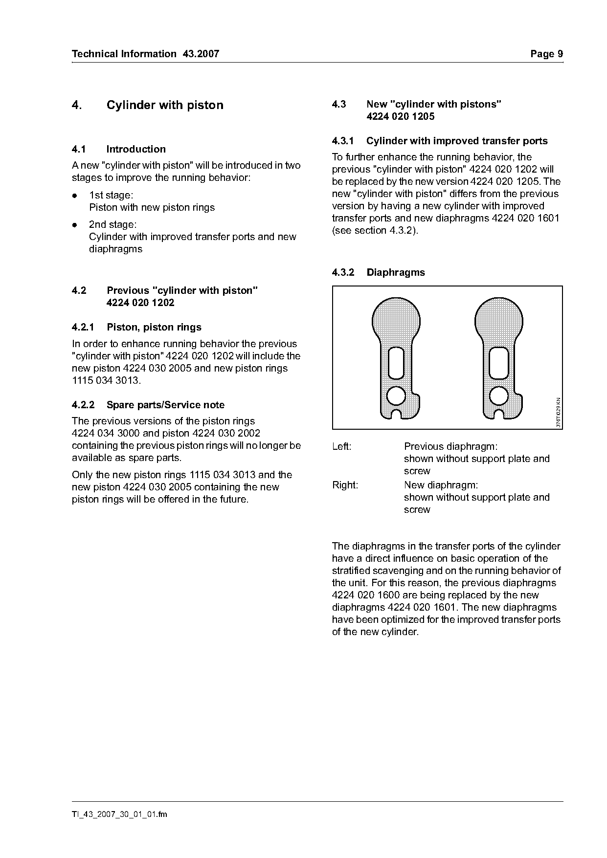
| 4224 020 1600 | 4224 020 1601 | For this reason, the previous diaphragms 4224 020 1600 are being replaced by the new diaphragms 4224 020 1601. |
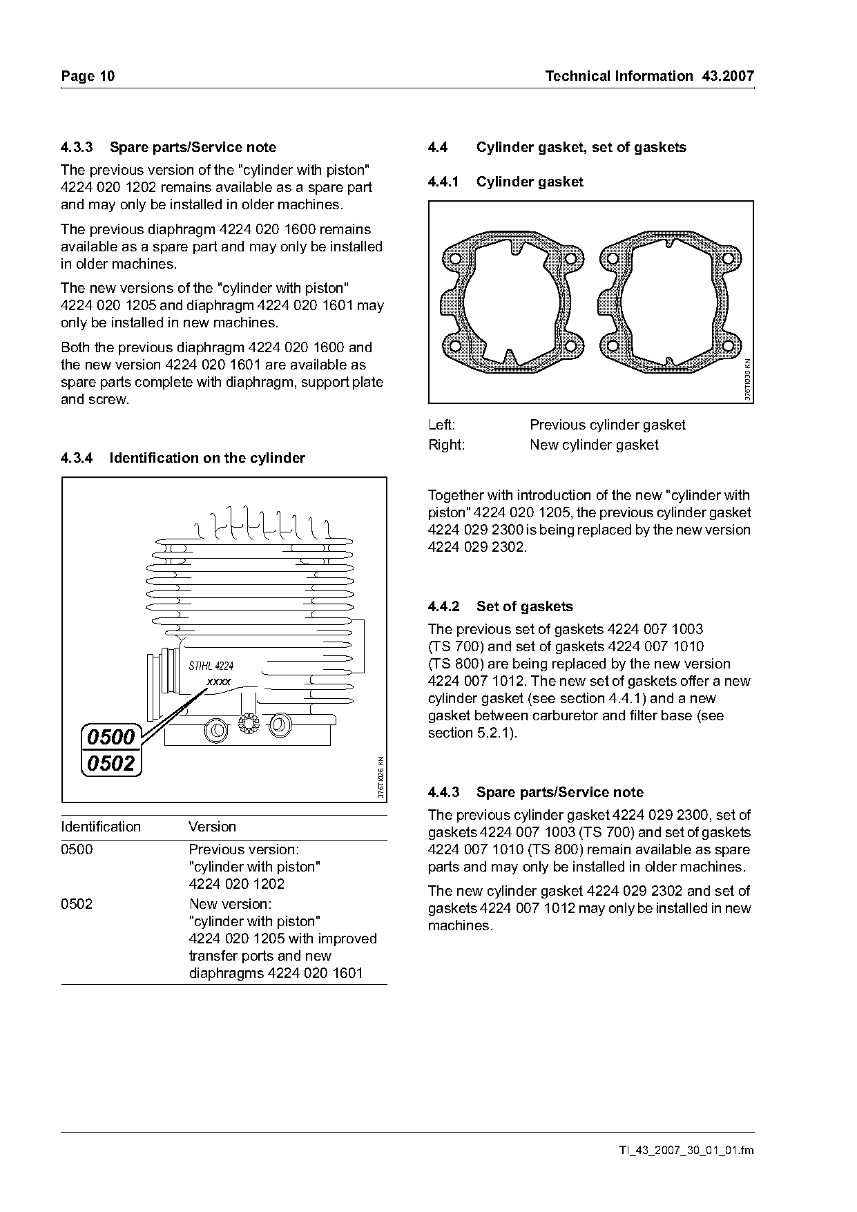
| 4224 029 2300 | 4224 029 2302 | Together with introduction of the new "cylinder with piston" 4224 020 1205, the previous cylinder gasket 4224 029 2300 is being replaced by the new version 4224 029 2302. |
| 4224 007 1010 | 4224 007 1012 | 2 Set of gaskets The previous set of gaskets 4224 007 1003 (TS 700) and set of gaskets 4224 007 1010 STIHL 4224 (TS 800) are being replaced by the new version XXXX 4224 007 1012. |
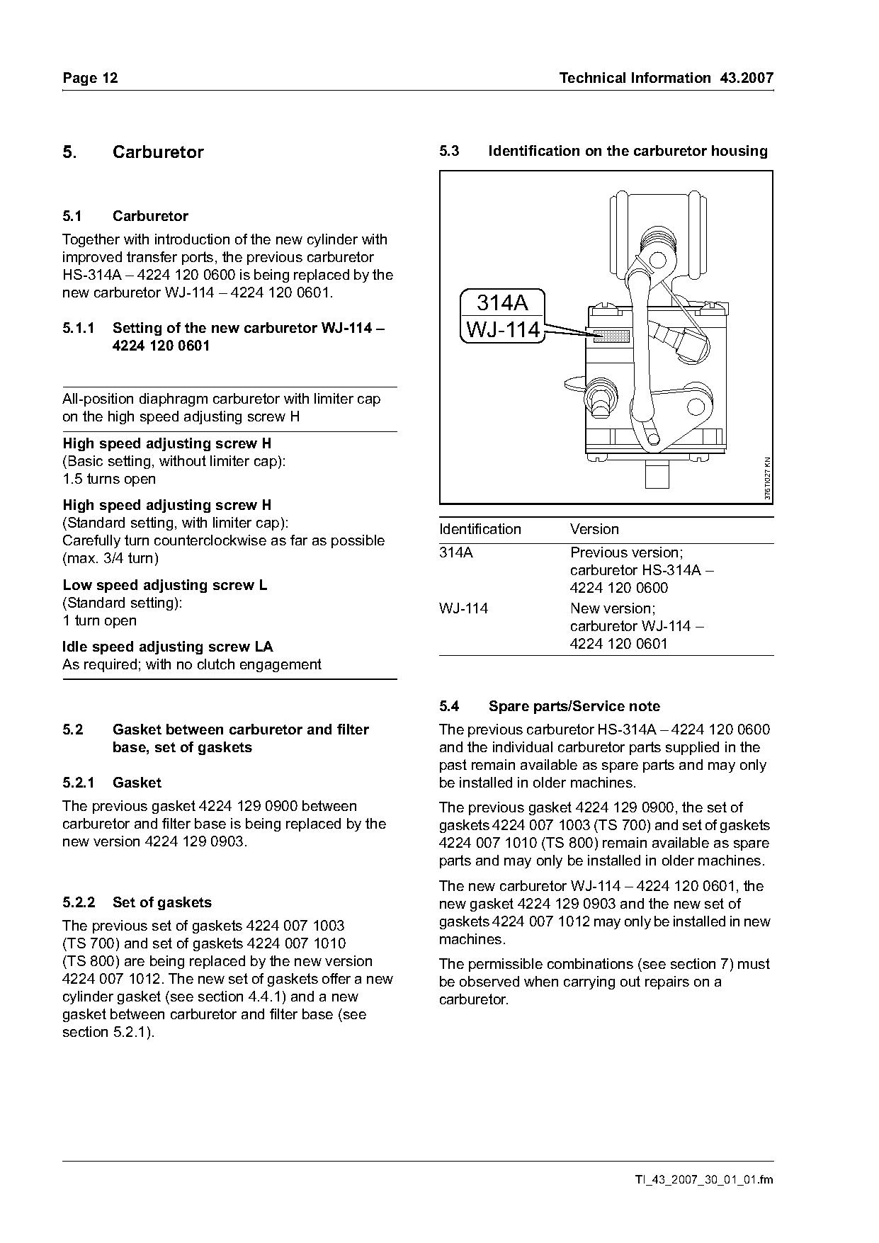
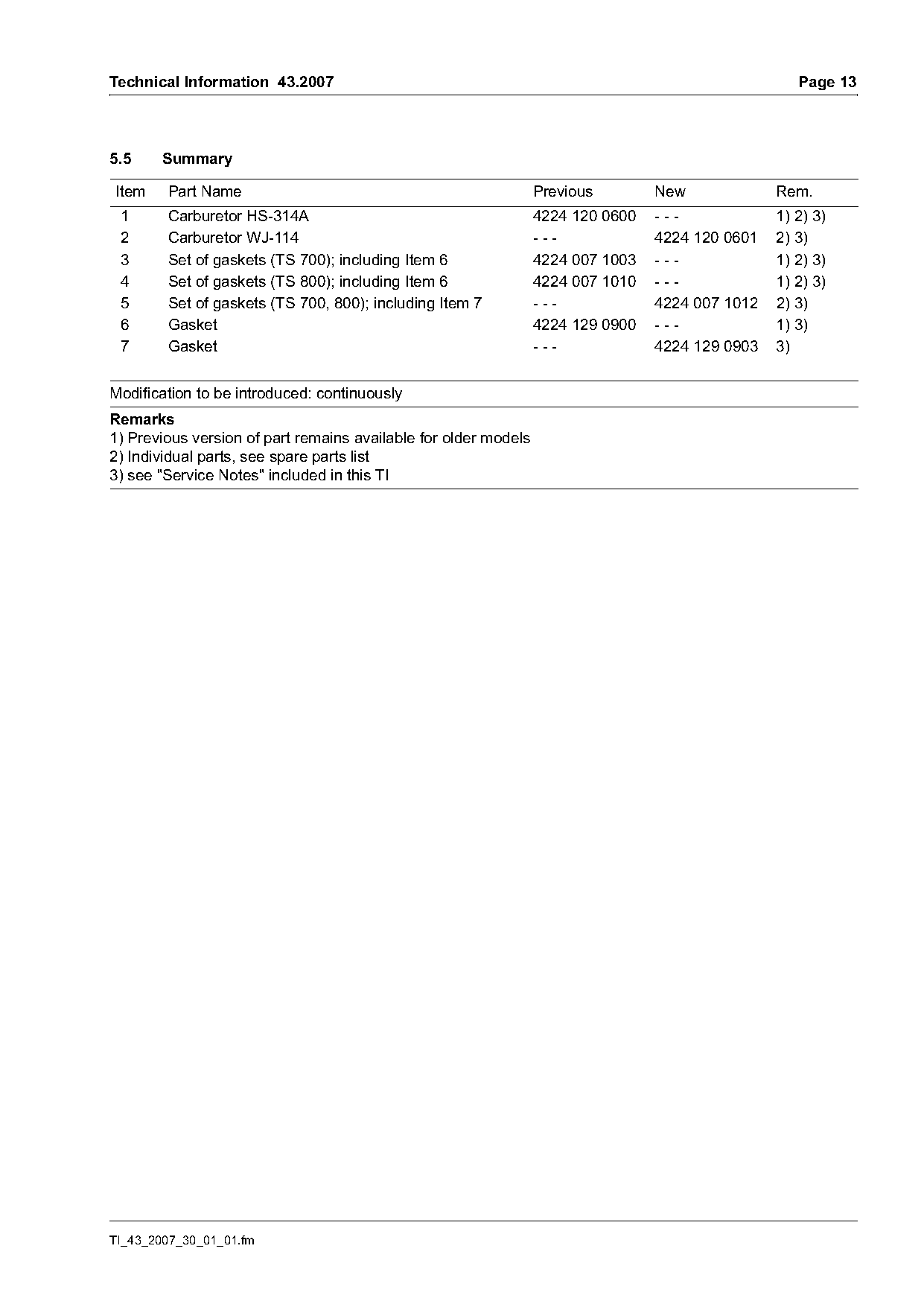
| 4224 120 0600 | 4224 120 0601 | 1 Carburetor Together with introduction of the new cylinder with improved transfer ports, the previous carburetor HS-314A – 4224 120 0600 is being replaced by the new carburetor WJ-114 – 4224 120 0601. |
| 4224 129 0900 | 4224 007 1003 | The previous gasket 4224 129 0900 between The previous gasket 4224 129 0900, the set of carburetor and filter base is being replaced by the gaskets 4224 007 1003 (TS 700) and set of gaskets new version 4224 129 0903. |
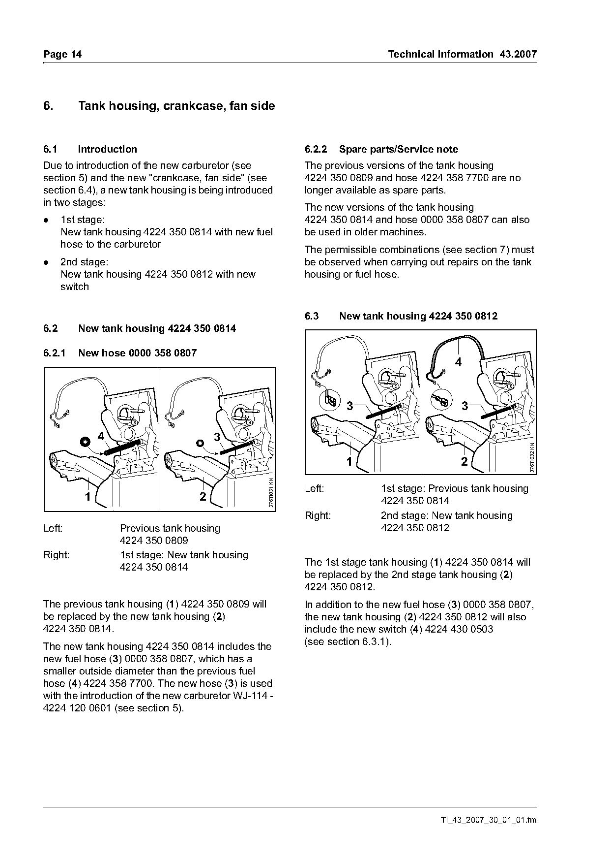
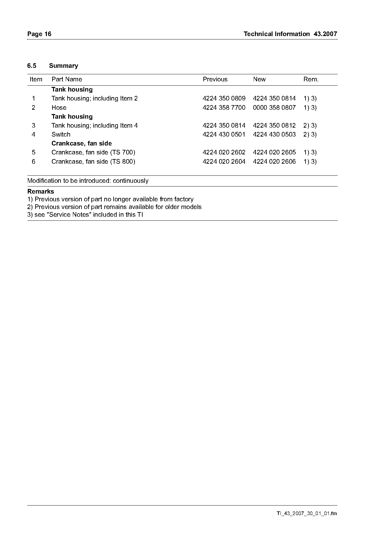
| 4224 350 0814 | 4224 350 0812 | Left: 1st stage: Previous tank housing 1 2 4224 350 0814 Right: 2nd stage: New tank housing Left: Previous tank housing 4224 350 0812 4224 350 0809 Right: 1st stage: New tank housing 4224 350 0814 The 1st stage tank housing (1) 4224 350 0814 will be replaced by the 2nd stage tank housing (2) 4224 35 |
| 4224 350 0809 | 4224 350 0812 | The previous tank housing (1) 4224 350 0809 will In addition to the new fuel hose (3) 0000 358 0807, be replaced by the new tank housing (2) the new tank housing (2) 4224 350 0812 will also 4224 350 0814. |
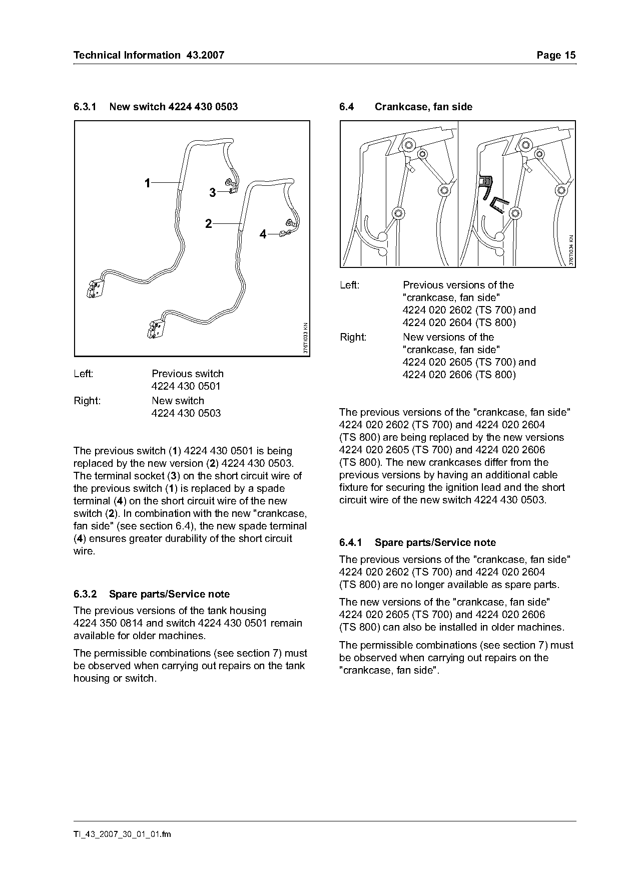
| 4224 020 2602 | 4224 430 0501 | Right: New versions of the "crankcase, fan side" 4224 020 2605 (TS 700) and Left: Previous switch 4224 020 2606 (TS 800) 4224 430 0501 Right: New switch 4224 430 0503 The previous versions of the "crankcase, fan side" 4224 020 2602 (TS 700) and 4224 020 2604 (TS 800) are being replaced by the new ve |
| 4224 020 2605 | 4224 430 0503 | Right: New versions of the "crankcase, fan side" 4224 020 2605 (TS 700) and Left: Previous switch 4224 020 2606 (TS 800) 4224 430 0501 Right: New switch 4224 430 0503 The previous versions of the "crankcase, fan side" 4224 020 2602 (TS 700) and 4224 020 2604 (TS 800) are being replaced by the new ve |
Full text
Page 1 of 18
Text of page 1 — search, copy, screen readers
STIH)

Technical Information                                                                43.2007

  Cut-off machines STIHL TS 700, 800 – Series 4224

  Contents
  1.   Introduction
  2.   Support with guard
  3.   Starter cover
  4.   Cylinder with piston
  5.   Carburetor
  6.   Tank housing, crankcase, fan side
  7.   Permissible combinations

  1.      Introduction
  In order to reduce the machine weight, the             To improve the durability of the short circuit wire,
  aluminum guard used in the past has been replaced      a new switch with a terminal socket is to be
  by the new magnesium guard.                            introduced, as well as a new "crankcase, fan side"
  To simplify servicing procedures, the poly V-belt      with an additional fixture for routing the short circuit
  pulley and shaft, the handlebar with corresponding     wire.
  fasteners and the water attachment have been           With the introduction of the new carburetor and
  changed.                                               switch a new tank housing will also be used.
  New hoses for the water supply and a new starter
  cover have been introduced to further improve
  operation when cutting with water.
  To enhance running behavior, a cylinder with
  improved transfer ports and diaphragms will be
  installed in the future, as well as a new carburetor
  which has been optimized for the new conditions.
  Both the cylinder gasket and the gasket between
  cylinder and filter base will also be changed.

  TI_43_2007_30_01_01.fm                                                                englisch / English USA
Page 2 of 18
Text of page 2 — search, copy, screen readers
Page 2                                                                                               Technical Information 43.2007

2.       Support with guard

2.1      Guard, adjusting lever, water supply                                    2.1.1   Mounting the water supply on the guard
         (TS 700)                                                                .   Slide the adjusting lever (2) onto the guard (1)
                                                                                     and secure it to the guard (1) with the screw (3).
                                              3
                             4                                                   .   Insert the banjo bolt (5) with sealing ring (6) and
                                 9
                                     6                                               fitted spline screw (4) into the connector (7).
                                         10
                    14
                                                           2                     .   Slide the square nut (8) into the guide on the
      11      13                                                                     inside of the guard (1) and tighten down the
                                         8
                                                                                     banjo bolt (5).
                                                                                 .   Install gasket (10) onto the banjo bolt (9) with the
                                                       1
                                                                                     sealing ring (6) and fitted spline screw (4).
                                              8                                  .   Slide the square nut (8) into the guide on the
                                                  76
                                                       5                             inside of the guard (1) and tighten down the
                                                               4
                                                                                     banjo bolt (9).

                                                                                 2.1.2   Adjusting screws
                                                                   376TI035 KN

                                                  12
                                                                                            1
                                                                                                                             2
The previous aluminum guard 4224 700 8103 is
being replaced by the new magnesium guard (1)
4224 700 8102.
On machines with new guards (1), the adjusting
lever (2) and all fasteners (4 to 10) for securing the
water supply to the guard will also change at the

                                                                                                                                       376TI028 KN
same time.
New versions of the rubber ring (11)
4224 706 8801, rubber ring (12) 4224 706 8802 and                                Together with the new guard, new adjusting screws
adjusting screws (see section 2.1.2) are being                                   will be introduced to secure the guard to the
introduced to secure the new guard (1) to the                                    unchanged support (1) 4224 791 3900.
unchanged support 4224 791 3900.
                                                                                 The new adjusting screw (2) is available as a spare
The new instruction labels (13, 14) have been                                    part under the Part number 4224 710 9501
adapted to fit the contour of the new guard (1).                                 complete with screw, sleeve and compression
                                                                                 spring.

                                                                                                                  TI_43_2007_30_01_01.fm
Page 3 of 18
Text of page 3 — search, copy, screen readers
Technical Information 43.2007                                                                                    Page 3

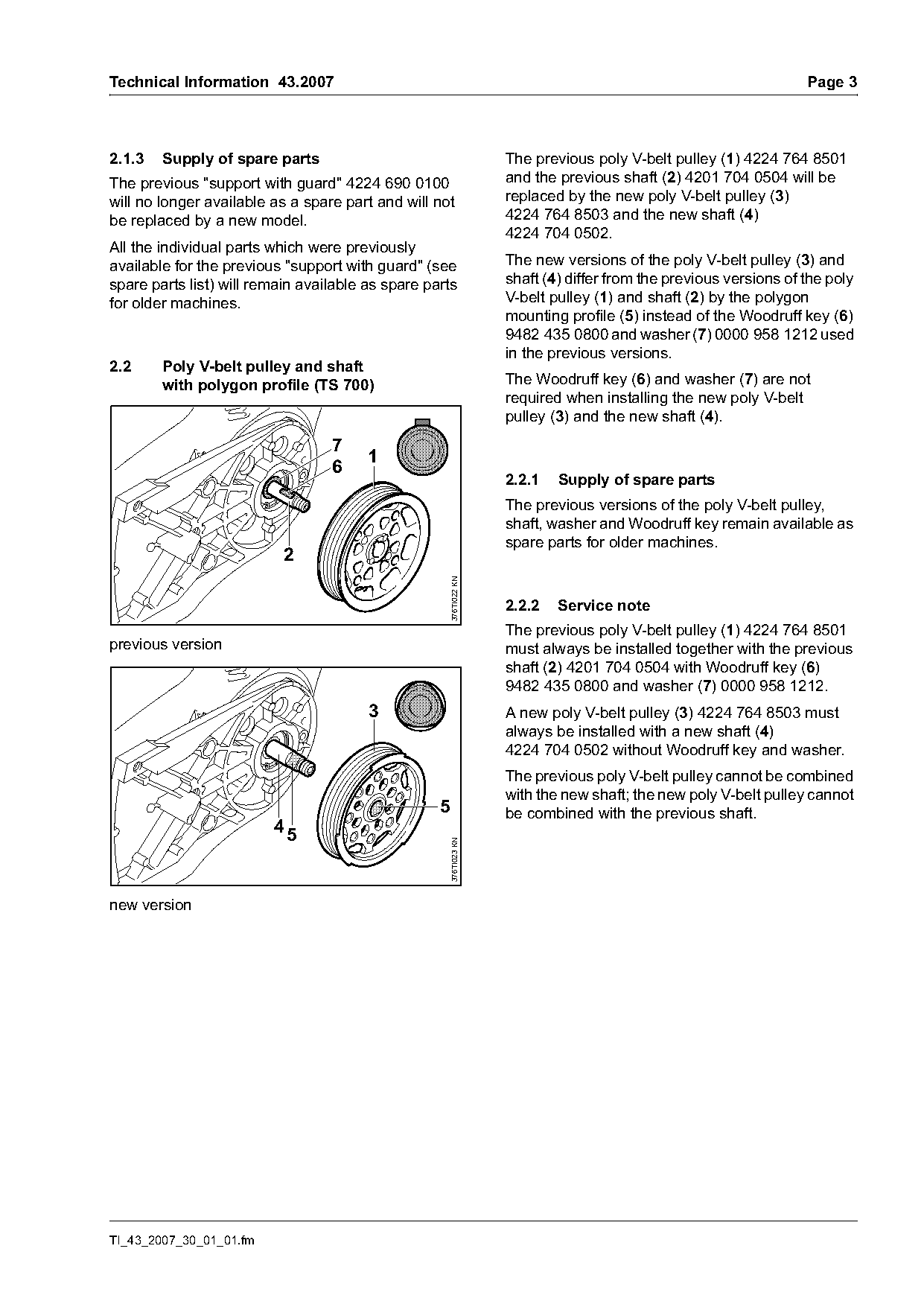
2.1.3   Supply of spare parts                                     The previous poly V-belt pulley (1) 4224 764 8501
The previous "support with guard" 4224 690 0100                   and the previous shaft (2) 4201 704 0504 will be
will no longer available as a spare part and will not             replaced by the new poly V-belt pulley (3)
be replaced by a new model.                                       4224 764 8503 and the new shaft (4)
                                                                  4224 704 0502.
All the individual parts which were previously
available for the previous "support with guard" (see              The new versions of the poly V-belt pulley (3) and
spare parts list) will remain available as spare parts            shaft (4) differ from the previous versions of the poly
for older machines.                                               V-belt pulley (1) and shaft (2) by the polygon
                                                                  mounting profile (5) instead of the Woodruff key (6)
                                                                  9482 435 0800 and washer (7) 0000 958 1212 used
                                                                  in the previous versions.
2.2     Poly V-belt pulley and shaft
        with polygon profile (TS 700)                             The Woodruff key (6) and washer (7) are not
                                                                  required when installing the new poly V-belt
                                                                  pulley (3) and the new shaft (4).
                                  7
                                        1
                                  6
                                                                  2.2.1   Supply of spare parts
                                                                  The previous versions of the poly V-belt pulley,
                                                                  shaft, washer and Woodruff key remain available as
                                                                  spare parts for older machines.
                           2
                                                    376TI022 KN

                                                                  2.2.2   Service note
                                                                  The previous poly V-belt pulley (1) 4224 764 8501
previous version                                                  must always be installed together with the previous
                                                                  shaft (2) 4201 704 0504 with Woodruff key (6)
                                                                  9482 435 0800 and washer (7) 0000 958 1212.
                                        3                         A new poly V-belt pulley (3) 4224 764 8503 must
                                                                  always be installed with a new shaft (4)
                                                                  4224 704 0502 without Woodruff key and washer.
                                                                  The previous poly V-belt pulley cannot be combined
                                                                  with the new shaft; the new poly V-belt pulley cannot
                                                   5              be combined with the previous shaft.
                         45
                                                    376TI023 KN

new version

TI_43_2007_30_01_01.fm
Page 4 of 18
Text of page 4 — search, copy, screen readers
Page 4                                                                               Technical Information 43.2007

2.3      Handlebar, water attachment (TS 700)                     2.4     Handlebar, water attachment (TS 800)

                     1 5                                                                1 5

                                         3                                                                    3


                                                    376TI024 KN

                                                                                                                      377TI005 KN
                                                                            2
                       4                                                                 4
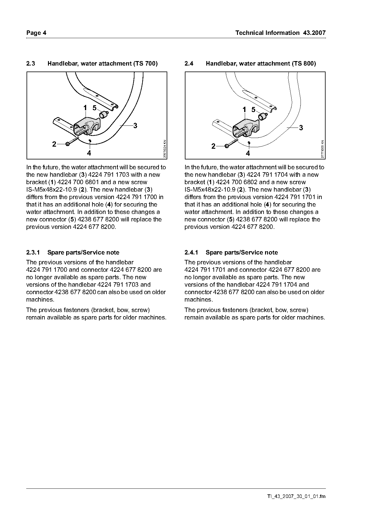
In the future, the water attachment will be secured to            In the future, the water attachment will be secured to
the new handlebar (3) 4224 791 1703 with a new                    the new handlebar (3) 4224 791 1704 with a new
bracket (1) 4224 700 6801 and a new screw                         bracket (1) 4224 700 6802 and a new screw
IS-M5x48x22-10.9 (2). The new handlebar (3)                       IS-M5x48x22-10.9 (2). The new handlebar (3)
differs from the previous version 4224 791 1700 in                differs from the previous version 4224 791 1701 in
that it has an additional hole (4) for securing the               that it has an additional hole (4) for securing the
water attachment. In addition to these changes a                  water attachment. In addition to these changes a
new connector (5) 4238 677 8200 will replace the                  new connector (5) 4238 677 8200 will replace the
previous version 4224 677 8200.                                   previous version 4224 677 8200.

2.3.1    Spare parts/Service note                                 2.4.1   Spare parts/Service note
The previous versions of the handlebar                            The previous versions of the handlebar
4224 791 1700 and connector 4224 677 8200 are                     4224 791 1701 and connector 4224 677 8200 are
no longer available as spare parts. The new                       no longer available as spare parts. The new
versions of the handlebar 4224 791 1703 and                       versions of the handlebar 4224 791 1704 and
connector 4238 677 8200 can also be used on older                 connector 4238 677 8200 can also be used on older
machines.                                                         machines.
The previous fasteners (bracket, bow, screw)                      The previous fasteners (bracket, bow, screw)
remain available as spare parts for older machines.               remain available as spare parts for older machines.

                                                                                                 TI_43_2007_30_01_01.fm
Page 5 of 18
Text of page 5 — search, copy, screen readers
Technical Information 43.2007                                                                          Page 5

2.5     Summary

Item    Part Name                                                 Previous        New             Rem.
        Support with guard (TS 700)
 1      Support with guard 350 mm;                                4224 690 0100   -*-             3)
        including Items 2, 5, 6, 8, 12, 14, 15, 16, 21, 23, 26,
        27, 29, 33, 35, 38, 40, 42, 43, 45, 50
        Guard (TS 700)
 2      Guard 350 mm                                              4224 700 8103   ---             2)
 3      Guard 350 mm; including Item 4                            ---             4224 700 8102
 4      Stiffener (2x)                                            ---             4238 706 0400
 5      Plug (2x)                                                 0000 706 4600   ---             2)
 6      Rubber ring                                               4221 706 8800   ---             2)
 7      Rubber ring                                               ---             4224 706 8801
 8      Rubber ring                                               4221 706 8801   ---             2)
 9      Rubber ring                                                               4224 706 8802
10      Instruction label                                         0000 967 3502   ---             2) 5)
11      Instruction label                                         ---             0000 967 3521
12      Instruction label                                         0000 967 3578   ---             2)
13      Instruction label                                         ---             0000 967 3520
14      Spline screw IS-M6x28-10.9 (4x)                           9022 341 1358   ---             2)
15      Sleeve (4x)                                               4224 704 3200   ---             2)
16      Compression spring (4x)                                   0000 997 1303   ---             2)
17      Adjusting screw (4x);                                     ---             4224 710 9501
        including Items 18, 19 and 20
18      Spline screw IS-M6x30-10.9                                ---             -*-
19      Sleeve                                                    ---             -*-
20      Compression spring                                        ---             -*-
        Adjusting lever, water supply (TS 700)
21      Adjusting lever; including Item 23                        4224 700 2900   ---             2)
22      Adjusting lever                                           ---             4224 700 2901
23      Hollow rivet DIN7340-AK6.5x0.5x3 (2x)                     9416 868 6510   ---             2)
24      Spline screw IS-M5x12-10.9 (2x)                           9022 341 0960   ---             2)
25      Spline screw IS-M5x30x22-10.9                             ---             9022 341 1070
26      Connector                                                 4224 677 8201   ---             2)
27      Connector                                                 4224 677 8202   ---             2)
28      Connector                                                 ---             4224 677 8203
29      Banjo bolt (2x)                                           4201 708 8400   ---             2)
30      Banjo bolt; including Item 32                             ---             0000 670 0200
31      Banjo bolt; including Item 32                             ---             0000 670 0201
32      Sealing ring DIN3770-B6x1.5 (2x)                          ---             9646 945 0340
33      Pan head screw DIN84-M5x10-5.8 (2x)                       9041 216 0950   ---             2)
34      Pan head screw DIN84-M4x8-8.8 (2x)                        ---             9041 216 0630
35      Hex nut DIN936-G1/8" (2x)                                 9211 021 8900   ---             2)
36      Gasket                                                    ---             0000 679 2000
37      Square nut (2x)                                           ---             4224 708 8300

TI_43_2007_30_01_01.fm
Page 6 of 18
Text of page 6 — search, copy, screen readers
Page 6                                                                         Technical Information 43.2007

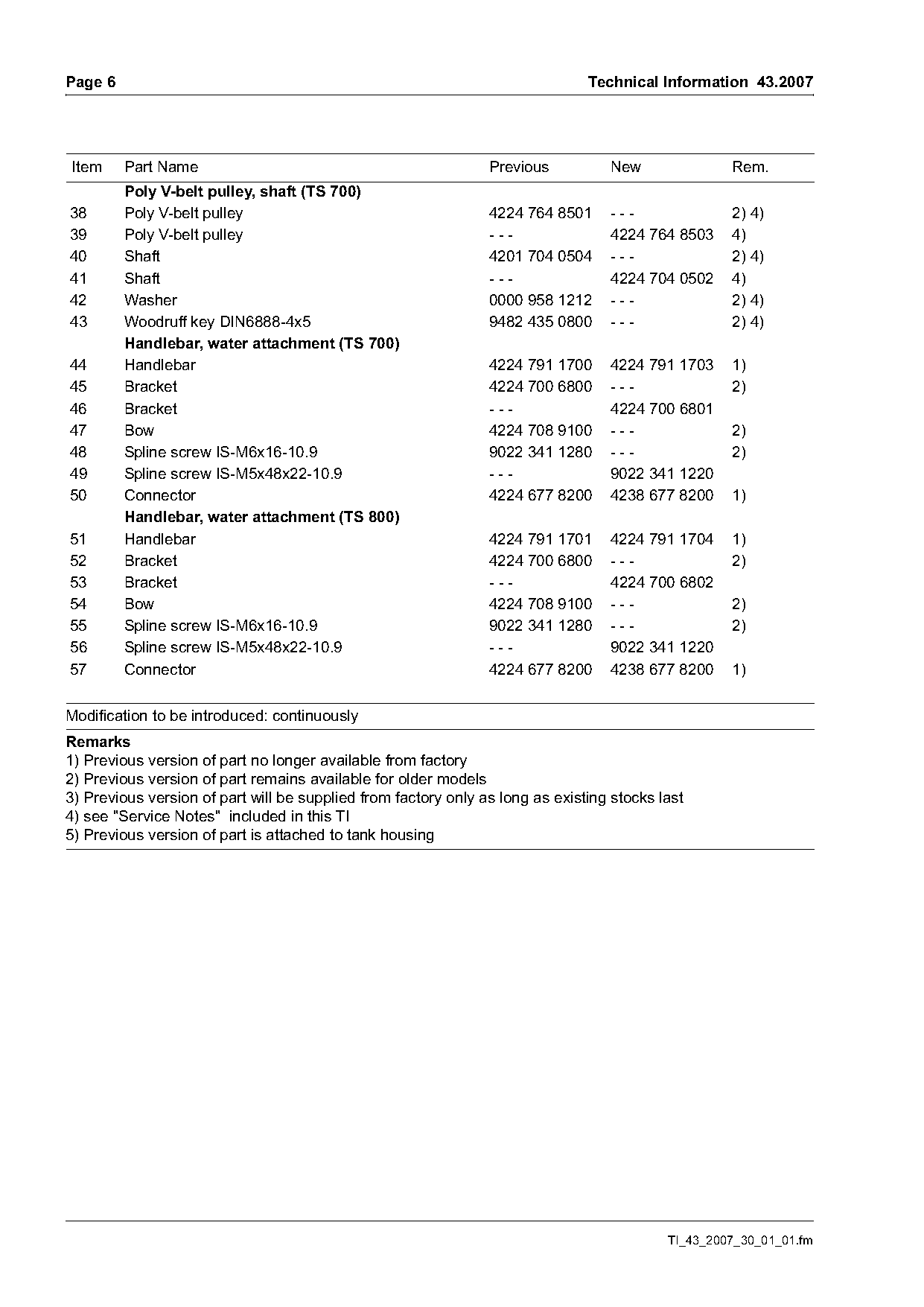
Item     Part Name                                              Previous          New               Rem.
         Poly V-belt pulley, shaft (TS 700)
38       Poly V-belt pulley                                     4224 764 8501     ---               2) 4)
39       Poly V-belt pulley                                     ---               4224 764 8503     4)
40       Shaft                                                  4201 704 0504     ---               2) 4)
41       Shaft                                                  ---               4224 704 0502     4)
42       Washer                                                 0000 958 1212     ---               2) 4)
43       Woodruff key DIN6888-4x5                               9482 435 0800     ---               2) 4)
         Handlebar, water attachment (TS 700)
44       Handlebar                                              4224 791 1700     4224 791 1703     1)
45       Bracket                                                4224 700 6800     ---               2)
46       Bracket                                                ---               4224 700 6801
47       Bow                                                    4224 708 9100     ---               2)
48       Spline screw IS-M6x16-10.9                             9022 341 1280     ---               2)
49       Spline screw IS-M5x48x22-10.9                          ---               9022 341 1220
50       Connector                                              4224 677 8200     4238 677 8200     1)
         Handlebar, water attachment (TS 800)
51       Handlebar                                              4224 791 1701     4224 791 1704     1)
52       Bracket                                                4224 700 6800     ---               2)
53       Bracket                                                ---               4224 700 6802
54       Bow                                                    4224 708 9100     ---               2)
55       Spline screw IS-M6x16-10.9                             9022 341 1280     ---               2)
56       Spline screw IS-M5x48x22-10.9                          ---               9022 341 1220
57       Connector                                              4224 677 8200     4238 677 8200     1)

Modification to be introduced: continuously
Remarks
1) Previous version of part no longer available from factory
2) Previous version of part remains available for older models
3) Previous version of part will be supplied from factory only as long as existing stocks last
4) see "Service Notes" included in this TI
5) Previous version of part is attached to tank housing

                                                                                           TI_43_2007_30_01_01.fm
Page 7 of 18
Text of page 7 — search, copy, screen readers
Technical Information 43.2007                                                                                 Page 7

3.      Starter cover                                             3.2     Water supply hoses, hose clip
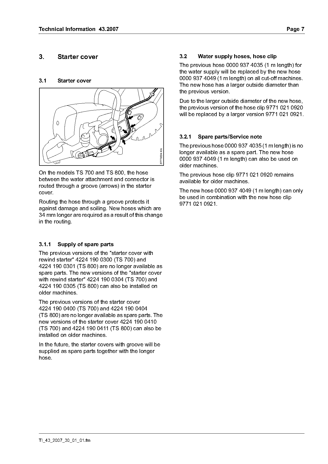
                                                                  The previous hose 0000 937 4035 (1 m length) for
                                                                  the water supply will be replaced by the new hose
3.1     Starter cover                                             0000 937 4049 (1 m length) on all cut-off machines.
                                                                  The new hose has a larger outside diameter than
                                                                  the previous version.
                                                                  Due to the larger outside diameter of the new hose,
                                                                  the previous version of the hose clip 9771 021 0920
                                                                  will be replaced by a larger version 9771 021 0921.

                                                                  3.2.1   Spare parts/Service note
                                                                  The previous hose 0000 937 4035 (1 m length) is no

                                                    377TI004 KN
                                                                  longer available as a spare part. The new hose
                                                                  0000 937 4049 (1 m length) can also be used on
                                                                  older machines.
On the models TS 700 and TS 800, the hose                         The previous hose clip 9771 021 0920 remains
between the water attachment and connector is                     available for older machines.
routed through a groove (arrows) in the starter
cover.                                                            The new hose 0000 937 4049 (1 m length) can only
                                                                  be used in combination with the new hose clip
Routing the hose through a groove protects it                     9771 021 0921.
against damage and soiling. New hoses which are
34 mm longer are required as a result of this change
in the routing.

3.1.1   Supply of spare parts
The previous versions of the "starter cover with
rewind starter" 4224 190 0300 (TS 700) and
4224 190 0301 (TS 800) are no longer available as
spare parts. The new versions of the "starter cover
with rewind starter" 4224 190 0304 (TS 700) and
4224 190 0305 (TS 800) can also be installed on
older machines.
The previous versions of the starter cover
4224 190 0400 (TS 700) and 4224 190 0404
(TS 800) are no longer available as spare parts. The
new versions of the starter cover 4224 190 0410
(TS 700) and 4224 190 0411 (TS 800) can also be
installed on older machines.
In the future, the starter covers with groove will be
supplied as spare parts together with the longer
hose.

TI_43_2007_30_01_01.fm
Page 8 of 18
Text of page 8 — search, copy, screen readers
Page 8                                                                     Technical Information 43.2007

3.3      Summary

Item     Part Name                                           Previous         New               Rem.
         Starter cover
 1       Starter cover with rewind starter (TS 700);         4224 190 0300    ---               1)
         including Item 3, 5
 2       Starter cover with rewind starter (TS 700);         ---              4224 190 0304
         including Item 4, 6
 3       Starter cover; including Item 5                     4224 190 0400    ---               1)
 4       Starter cover; including Item 6                     ---              4224 190 0410
 5       Hose 6.0 x 1.5 mm x 580 mm                          -*-              ---
 6       Hose 5.6 x 1.9 mm x 614 mm                          ---              -*-               4)
 7       Starter cover with rewind starter (TS 800);         4224 190 0301    ---               1)
         including Item 9, 11
 8       Starter cover with rewind starter (TS 800);         ---              4224 190 0305
         including Item 10, 12
 9       Starter cover; including Item 11                    4224 190 0404    ---               1)
10       Starter cover; including Item 12                    ---              4224 190 0411
11       Hose 6.0 x 1.5 mm x 640 mm                          -*-              ---
12       Hose 5.6 x 1.9 mm x 674 mm                          ---              -*-               4)
         Hose, hose clip
13       Hose 6.0 x 1.5 mm x 1 m                             0000 937 4035    ---               1)
14       Hose 5.6 x 1.9 mm x 1 m                             ---              0000 937 4049     3)
15       Hose clip 9.5/7 (4x)                                9771 021 0920    ---               2) 3)
16       Hose clip 10/7 (4x)                                 ---              9771 021 0921     3)

Modification to be introduced: continuously
Remarks
1) Previous version of part no longer available from factory
2) Previous version of part remains available for older models
3) see "Service Notes" included in this TI
4) Part is not available separately as a cut length (recommended length must be cut from
1m length – 0000 937 4049)

                                                                                       TI_43_2007_30_01_01.fm
Page 9 of 18
Text of page 9 — search, copy, screen readers
Technical Information 43.2007                                                                         Page 9

4.       Cylinder with piston                            4.3      New "cylinder with pistons"
                                                                  4224 020 1205

                                                         4.3.1    Cylinder with improved transfer ports
4.1      Introduction
                                                         To further enhance the running behavior, the
A new "cylinder with piston" will be introduced in two   previous "cylinder with piston" 4224 020 1202 will
stages to improve the running behavior:                  be replaced by the new version 4224 020 1205. The
.     1st stage:                                         new "cylinder with piston" differs from the previous
      Piston with new piston rings                       version by having a new cylinder with improved
                                                         transfer ports and new diaphragms 4224 020 1601
.     2nd stage:
                                                         (see section 4.3.2).
      Cylinder with improved transfer ports and new
      diaphragms

                                                         4.3.2    Diaphragms
4.2      Previous "cylinder with piston"
         4224 020 1202

4.2.1    Piston, piston rings
In order to enhance running behavior the previous
"cylinder with piston" 4224 020 1202 will include the
new piston 4224 030 2005 and new piston rings
1115 034 3013.

                                                                                                           376TI029 KN
4.2.2    Spare parts/Service note
The previous versions of the piston rings
4224 034 3000 and piston 4224 030 2002
containing the previous piston rings will no longer be   Left:           Previous diaphragm:
available as spare parts.                                                shown without support plate and
Only the new piston rings 1115 034 3013 and the                          screw
new piston 4224 030 2005 containing the new              Right:          New diaphragm:
piston rings will be offered in the future.                              shown without support plate and
                                                                         screw

                                                         The diaphragms in the transfer ports of the cylinder
                                                         have a direct influence on basic operation of the
                                                         stratified scavenging and on the running behavior of
                                                         the unit. For this reason, the previous diaphragms
                                                         4224 020 1600 are being replaced by the new
                                                         diaphragms 4224 020 1601. The new diaphragms
                                                         have been optimized for the improved transfer ports
                                                         of the new cylinder.

TI_43_2007_30_01_01.fm
Page 10 of 18
Text of page 10 — search, copy, screen readers
Page 10                                                                               Technical Information 43.2007

4.3.3   Spare parts/Service note                                   4.4      Cylinder gasket, set of gaskets
The previous version of the "cylinder with piston"
4224 020 1202 remains available as a spare part                    4.4.1    Cylinder gasket
and may only be installed in older machines.
The previous diaphragm 4224 020 1600 remains
available as a spare part and may only be installed
in older machines.
The new versions of the "cylinder with piston"
4224 020 1205 and diaphragm 4224 020 1601 may
only be installed in new machines.
Both the previous diaphragm 4224 020 1600 and
the new version 4224 020 1601 are available as

                                                                                                                     376TI030 KN
spare parts complete with diaphragm, support plate
and screw.
                                                                   Left:           Previous cylinder gasket
                                                                   Right:          New cylinder gasket
4.3.4   Identification on the cylinder

                                                                   Together with introduction of the new "cylinder with
                                                                   piston" 4224 020 1205, the previous cylinder gasket
                                                                   4224 029 2300 is being replaced by the new version
                                                                   4224 029 2302.

                                                                   4.4.2    Set of gaskets
                                                                   The previous set of gaskets 4224 007 1003
                                                                   (TS 700) and set of gaskets 4224 007 1010
                    STIHL 4224                                     (TS 800) are being replaced by the new version
                        XXXX                                       4224 007 1012. The new set of gaskets offer a new
                                                                   cylinder gasket (see section 4.4.1) and a new
                                                                   gasket between carburetor and filter base (see
    0500                                                           section 5.2.1).

    0502
                                                     376TI026 KN

                                                                   4.4.3    Spare parts/Service note
                                                                   The previous cylinder gasket 4224 029 2300, set of
Identification      Version                                        gaskets 4224 007 1003 (TS 700) and set of gaskets
0500                Previous version:                              4224 007 1010 (TS 800) remain available as spare
                    "cylinder with piston"                         parts and may only be installed in older machines.
                    4224 020 1202                                  The new cylinder gasket 4224 029 2302 and set of
0502                New version:                                   gaskets 4224 007 1012 may only be installed in new
                    "cylinder with piston"                         machines.
                    4224 020 1205 with improved
                    transfer ports and new
                    diaphragms 4224 020 1601

                                                                                                 TI_43_2007_30_01_01.fm
Page 11 of 18
Text of page 11 — search, copy, screen readers
Technical Information 43.2007                                                                       Page 11

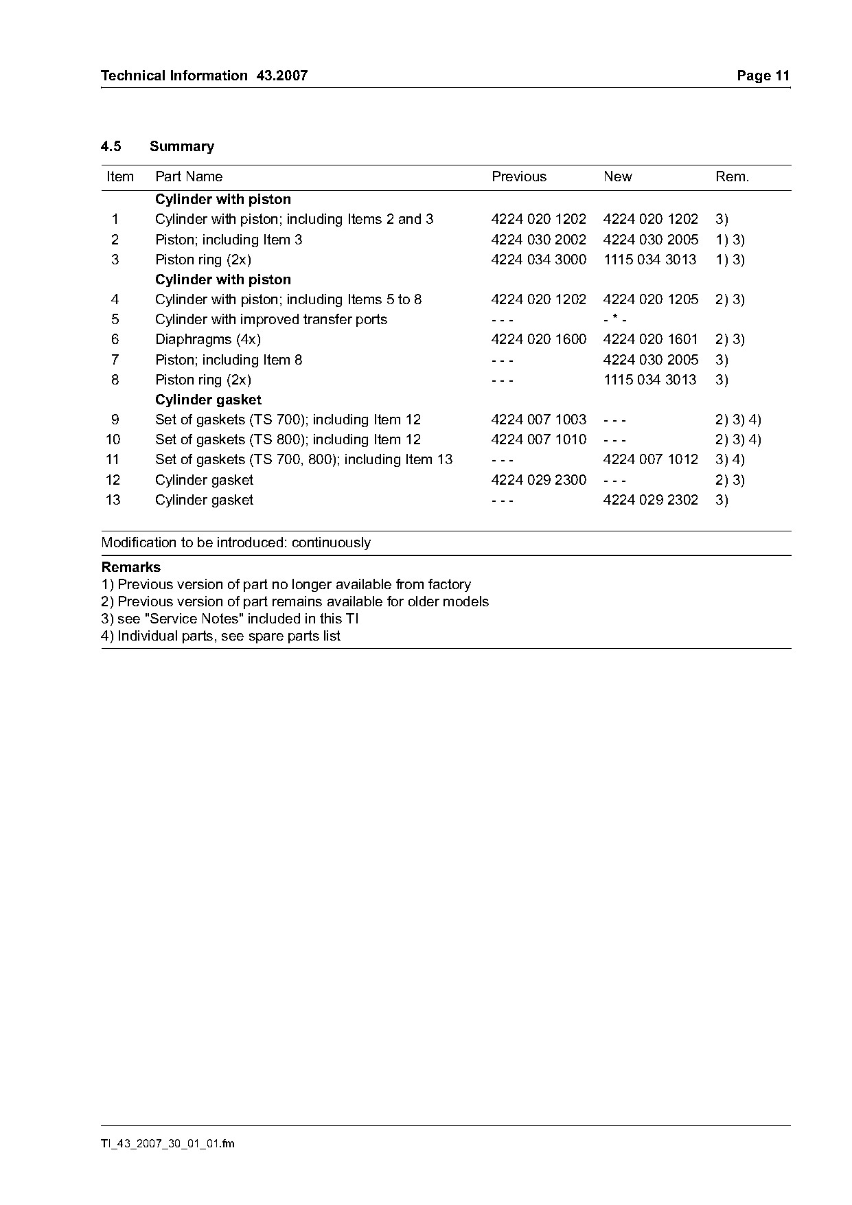
4.5     Summary

Item    Part Name                                                Previous        New             Rem.
        Cylinder with piston
 1      Cylinder with piston; including Items 2 and 3            4224 020 1202   4224 020 1202   3)
 2      Piston; including Item 3                                 4224 030 2002   4224 030 2005   1) 3)
 3      Piston ring (2x)                                         4224 034 3000   1115 034 3013   1) 3)
        Cylinder with piston
 4      Cylinder with piston; including Items 5 to 8             4224 020 1202   4224 020 1205   2) 3)
 5      Cylinder with improved transfer ports                    ---             -*-
 6      Diaphragms (4x)                                          4224 020 1600   4224 020 1601   2) 3)
 7      Piston; including Item 8                                 ---             4224 030 2005   3)
 8      Piston ring (2x)                                         ---             1115 034 3013   3)
        Cylinder gasket
 9      Set of gaskets (TS 700); including Item 12               4224 007 1003   ---             2) 3) 4)
10      Set of gaskets (TS 800); including Item 12               4224 007 1010   ---             2) 3) 4)
11      Set of gaskets (TS 700, 800); including Item 13          ---             4224 007 1012   3) 4)
12      Cylinder gasket                                          4224 029 2300   ---             2) 3)
13      Cylinder gasket                                          ---             4224 029 2302   3)

Modification to be introduced: continuously
Remarks
1) Previous version of part no longer available from factory
2) Previous version of part remains available for older models
3) see "Service Notes" included in this TI
4) Individual parts, see spare parts list

TI_43_2007_30_01_01.fm
Page 12 of 18
Text of page 12 — search, copy, screen readers
Page 12                                                                  Technical Information 43.2007

5.      Carburetor                                    5.3      Identification on the carburetor housing

5.1     Carburetor
Together with introduction of the new cylinder with
improved transfer ports, the previous carburetor
HS-314A – 4224 120 0600 is being replaced by the
new carburetor WJ-114 – 4224 120 0601.
                                                             314A
5.1.1   Setting of the new carburetor WJ-114 –              WJ-114
        4224 120 0601

All-position diaphragm carburetor with limiter cap
on the high speed adjusting screw H
High speed adjusting screw H
(Basic setting, without limiter cap):

                                                                                                        376TI027 KN
1.5 turns open
High speed adjusting screw H
(Standard setting, with limiter cap):                 Identification      Version
Carefully turn counterclockwise as far as possible
(max. 3/4 turn)                                       314A                Previous version;
                                                                          carburetor HS-314A –
Low speed adjusting screw L                                               4224 120 0600
(Standard setting):                                   WJ-114              New version;
1 turn open                                                               carburetor WJ-114 –
Idle speed adjusting screw LA                                             4224 120 0601
As required; with no clutch engagement

                                                      5.4      Spare parts/Service note
5.2     Gasket between carburetor and filter          The previous carburetor HS-314A – 4224 120 0600
        base, set of gaskets                          and the individual carburetor parts supplied in the
                                                      past remain available as spare parts and may only
5.2.1   Gasket                                        be installed in older machines.
The previous gasket 4224 129 0900 between             The previous gasket 4224 129 0900, the set of
carburetor and filter base is being replaced by the   gaskets 4224 007 1003 (TS 700) and set of gaskets
new version 4224 129 0903.                            4224 007 1010 (TS 800) remain available as spare
                                                      parts and may only be installed in older machines.
                                                      The new carburetor WJ-114 – 4224 120 0601, the
5.2.2   Set of gaskets                                new gasket 4224 129 0903 and the new set of
The previous set of gaskets 4224 007 1003             gaskets 4224 007 1012 may only be installed in new
(TS 700) and set of gaskets 4224 007 1010             machines.
(TS 800) are being replaced by the new version        The permissible combinations (see section 7) must
4224 007 1012. The new set of gaskets offer a new     be observed when carrying out repairs on a
cylinder gasket (see section 4.4.1) and a new         carburetor.
gasket between carburetor and filter base (see
section 5.2.1).

                                                                                    TI_43_2007_30_01_01.fm
Page 13 of 18
Text of page 13 — search, copy, screen readers
Technical Information 43.2007                                                                       Page 13

5.5     Summary

Item    Part Name                                                Previous        New             Rem.
 1      Carburetor HS-314A                                       4224 120 0600   ---             1) 2) 3)
 2      Carburetor WJ-114                                        ---             4224 120 0601   2) 3)
 3      Set of gaskets (TS 700); including Item 6                4224 007 1003   ---             1) 2) 3)
 4      Set of gaskets (TS 800); including Item 6                4224 007 1010   ---             1) 2) 3)
 5      Set of gaskets (TS 700, 800); including Item 7           ---             4224 007 1012   2) 3)
 6      Gasket                                                   4224 129 0900   ---             1) 3)
 7      Gasket                                                   ---             4224 129 0903   3)

Modification to be introduced: continuously
Remarks
1) Previous version of part remains available for older models
2) Individual parts, see spare parts list
3) see "Service Notes" included in this TI

TI_43_2007_30_01_01.fm
Page 14 of 18
Text of page 14 — search, copy, screen readers
Page 14                                                                            Technical Information 43.2007

6.       Tank housing, crankcase, fan side

6.1      Introduction                                            6.2.2    Spare parts/Service note
Due to introduction of the new carburetor (see                   The previous versions of the tank housing
section 5) and the new "crankcase, fan side" (see                4224 350 0809 and hose 4224 358 7700 are no
section 6.4), a new tank housing is being introduced             longer available as spare parts.
in two stages:                                                   The new versions of the tank housing
.     1st stage:                                                 4224 350 0814 and hose 0000 358 0807 can also
      New tank housing 4224 350 0814 with new fuel               be used in older machines.
      hose to the carburetor
                                                                 The permissible combinations (see section 7) must
.     2nd stage:                                                 be observed when carrying out repairs on the tank
      New tank housing 4224 350 0812 with new                    housing or fuel hose.
      switch

                                                                 6.3      New tank housing 4224 350 0812
6.2      New tank housing 4224 350 0814

6.2.1    New hose 0000 358 0807
                                                                                                  4

                                                                           3                         3

              4                        3

                                                                                                                     376TI032 KN
                                                                           1                         2
                                                   376TI031 KN

                                                                 Left:            1st stage: Previous tank housing
          1                        2                                              4224 350 0814
                                                                 Right:           2nd stage: New tank housing
Left:             Previous tank housing                                           4224 350 0812
                  4224 350 0809
Right:            1st stage: New tank housing
                  4224 350 0814                                  The 1st stage tank housing (1) 4224 350 0814 will
                                                                 be replaced by the 2nd stage tank housing (2)
                                                                 4224 350 0812.
The previous tank housing (1) 4224 350 0809 will                 In addition to the new fuel hose (3) 0000 358 0807,
be replaced by the new tank housing (2)                          the new tank housing (2) 4224 350 0812 will also
4224 350 0814.                                                   include the new switch (4) 4224 430 0503
The new tank housing 4224 350 0814 includes the                  (see section 6.3.1).
new fuel hose (3) 0000 358 0807, which has a
smaller outside diameter than the previous fuel
hose (4) 4224 358 7700. The new hose (3) is used
with the introduction of the new carburetor WJ-114 -
4224 120 0601 (see section 5).

                                                                                               TI_43_2007_30_01_01.fm
Page 15 of 18
Text of page 15 — search, copy, screen readers
Technical Information 43.2007                                                                               Page 15

6.3.1    New switch 4224 430 0503                               6.4      Crankcase, fan side

               1
                              3

                              2
                                         4

                                                                                                                    376TI034 KN
                                                                Left:         Previous versions of the
                                                                              "crankcase, fan side"
                                                                              4224 020 2602 (TS 700) and
                                                                              4224 020 2604 (TS 800)
                                                  376TI033 KN

                                                                Right:        New versions of the
                                                                              "crankcase, fan side"
                                                                              4224 020 2605 (TS 700) and
Left:              Previous switch                                            4224 020 2606 (TS 800)
                   4224 430 0501
Right:             New switch
                   4224 430 0503                                The previous versions of the "crankcase, fan side"
                                                                4224 020 2602 (TS 700) and 4224 020 2604
                                                                (TS 800) are being replaced by the new versions
The previous switch (1) 4224 430 0501 is being                  4224 020 2605 (TS 700) and 4224 020 2606
replaced by the new version (2) 4224 430 0503.                  (TS 800). The new crankcases differ from the
The terminal socket (3) on the short circuit wire of            previous versions by having an additional cable
the previous switch (1) is replaced by a spade                  fixture for securing the ignition lead and the short
terminal (4) on the short circuit wire of the new               circuit wire of the new switch 4224 430 0503.
switch (2). In combination with the new "crankcase,
fan side" (see section 6.4), the new spade terminal
(4) ensures greater durability of the short circuit             6.4.1    Spare parts/Service note
wire.
                                                                The previous versions of the "crankcase, fan side"
                                                                4224 020 2602 (TS 700) and 4224 020 2604
                                                                (TS 800) are no longer available as spare parts.
6.3.2    Spare parts/Service note
                                                                The new versions of the "crankcase, fan side"
The previous versions of the tank housing                       4224 020 2605 (TS 700) and 4224 020 2606
4224 350 0814 and switch 4224 430 0501 remain                   (TS 800) can also be installed in older machines.
available for older machines.
                                                                The permissible combinations (see section 7) must
The permissible combinations (see section 7) must               be observed when carrying out repairs on the
be observed when carrying out repairs on the tank               "crankcase, fan side".
housing or switch.

TI_43_2007_30_01_01.fm
Page 16 of 18
Text of page 16 — search, copy, screen readers
Page 16                                                                      Technical Information 43.2007

6.5    Summary

Item    Part Name                                                Previous        New             Rem.
        Tank housing
 1      Tank housing; including Item 2                           4224 350 0809   4224 350 0814   1) 3)
 2      Hose                                                     4224 358 7700   0000 358 0807   1) 3)
        Tank housing
 3      Tank housing; including Item 4                           4224 350 0814   4224 350 0812   2) 3)
 4      Switch                                                   4224 430 0501   4224 430 0503   2) 3)
        Crankcase, fan side
 5      Crankcase, fan side (TS 700)                             4224 020 2602   4224 020 2605   1) 3)
 6      Crankcase, fan side (TS 800)                             4224 020 2604   4224 020 2606   1) 3)

Modification to be introduced: continuously
Remarks
1) Previous version of part no longer available from factory
2) Previous version of part remains available for older models
3) see "Service Notes" included in this TI

                                                                                        TI_43_2007_30_01_01.fm
Page 17 of 18
Text of page 17 — search, copy, screen readers
Technical Information 43.2007                                                                        Page 17

7.      Permissible combinations
Only the following combinations may be used when
carrying out repairs on tank housings, fuel hoses,
switches, "crankcases, fan side" or carburetors.
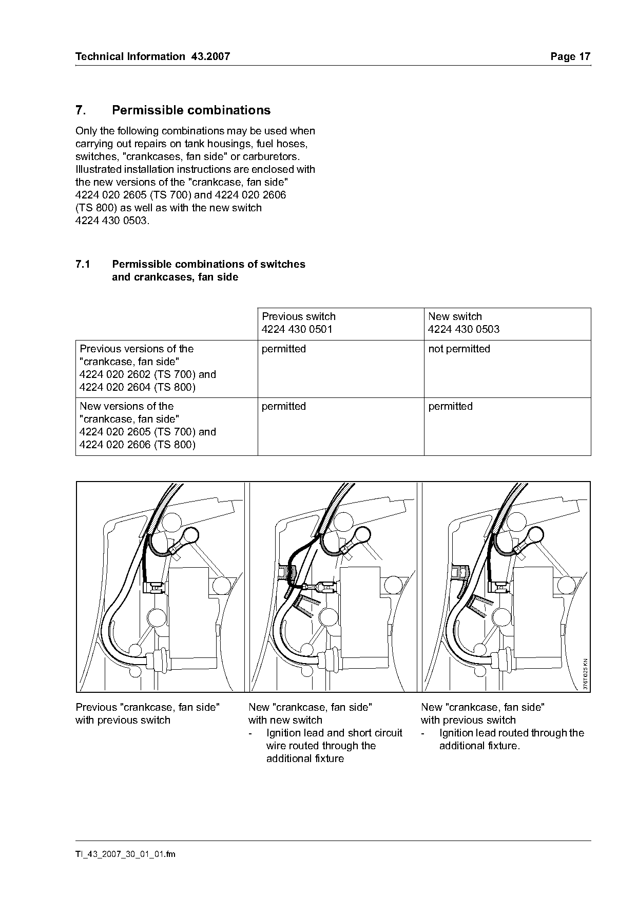
Illustrated installation instructions are enclosed with
the new versions of the "crankcase, fan side"
4224 020 2605 (TS 700) and 4224 020 2606
(TS 800) as well as with the new switch
4224 430 0503.

7.1     Permissible combinations of switches
        and crankcases, fan side

                                          Previous switch                   New switch
                                          4224 430 0501                     4224 430 0503
Previous versions of the                  permitted                         not permitted
"crankcase, fan side"
4224 020 2602 (TS 700) and
4224 020 2604 (TS 800)
New versions of the                       permitted                         permitted
"crankcase, fan side"
4224 020 2605 (TS 700) and
4224 020 2606 (TS 800)

                                                                                                            376TI025 KN

Previous "crankcase, fan side"         New "crankcase, fan side"           New "crankcase, fan side"
with previous switch                   with new switch                     with previous switch
                                       - Ignition lead and short circuit   - Ignition lead routed through the
                                           wire routed through the             additional fixture.
                                           additional fixture

TI_43_2007_30_01_01.fm
Page 18 of 18
Text of page 18 — search, copy, screen readers
Page 18                                                                      Technical Information 43.2007

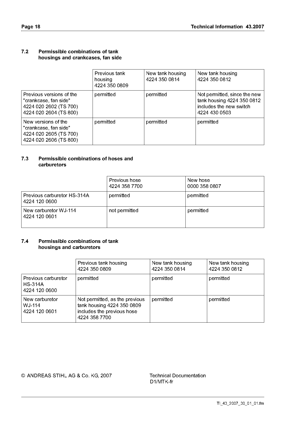
7.2   Permissible combinations of tank
      housings and crankcases, fan side

                               Previous tank             New tank housing       New tank housing
                               housing                   4224 350 0814          4224 350 0812
                               4224 350 0809
Previous versions of the       permitted                 permitted              Not permitted, since the new
"crankcase, fan side"                                                           tank housing 4224 350 0812
4224 020 2602 (TS 700)                                                          includes the new switch
4224 020 2604 (TS 800)                                                          4224 430 0503
New versions of the            permitted                 permitted              permitted
"crankcase, fan side"
4224 020 2605 (TS 700)
4224 020 2606 (TS 800)

7.3   Permissible combinations of hoses and
      carburetors

                                      Previous hose                         New hose
                                      4224 358 7700                         0000 358 0807
Previous carburetor HS-314A           permitted                             permitted
4224 120 0600
New carburetor WJ-114                 not permitted                         permitted
4224 120 0601

7.4   Permissible combinations of tank
      housings and carburetors

                        Previous tank housing              New tank housing             New tank housing
                        4224 350 0809                      4224 350 0814                4224 350 0812
Previous carburetor     permitted                          permitted                    permitted
HS-314A
4224 120 0600
New carburetor          Not permitted, as the previous     permitted                    permitted
WJ-114                  tank housing 4224 350 0809
4224 120 0601           includes the previous hose
                        4224 358 7700

© ANDREAS STIHL AG & Co. KG, 2007                         Technical Documentation
                                                          D1/MTK-fr

                                                                                           TI_43_2007_30_01_01.fm
Most of these PDFs embed fonts with a shifted character map, so the text above was recovered rather than copied — read it as a faithful but imperfect transcription, and treat the page image above each block as the authority where the two disagree — the figures exist only there, because they are vector drawings that text extraction cannot keep.