Technical Information · issue 52 of 2007
New STIHL FSB-KM Trimmer KombiTool
IssueTI 52/2007
Full text
Page 1 of 6
Text of page 1 — search, copy, screen readers
STIH)

Technical Information                                              52.2007

  New STIHL FSB-KM Trimmer KombiTool – Series 4137

  Contents
  1.   Technical Description
  2.   Approved KombiEngines
  3.   Approved Cutting Tools
  4.   Assembling the KombiTool
  5.   Specifications
  6.   Accessories
  7.   Spare Parts
  8.   Repairs

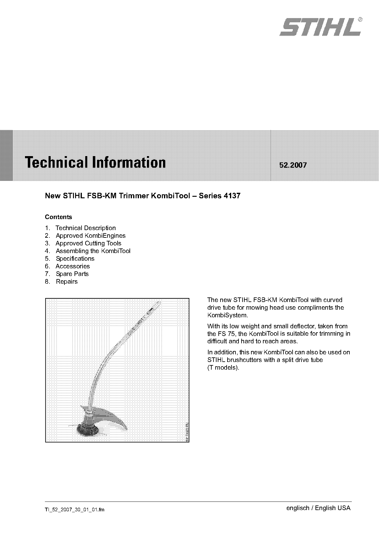
                                         The new STIHL FSB-KM KombiTool with curved
                                         drive tube for mowing head use compliments the
                                         KombiSystem.
                                         With its low weight and small deflector, taken from
                                         the FS 75, the KombiTool is suitable for trimming in
                                         difficult and hard to reach areas.
                                         In addition, this new KombiTool can also be used on
                                         STIHL brushcutters with a split drive tube
                                         (T models).

  TI_52_2007_30_01_01.fm                                             englisch / English USA
Page 2 of 6
Text of page 2 — search, copy, screen readers
Page 2                                                                   Technical Information 52.2007

1.       Technical Description                      3.       Approved Cutting Tools
                                                    The following cutting tools are approved:
               A

                              392TI053 KN

                                                               1                         2

                                                                                                         002TI034 BL
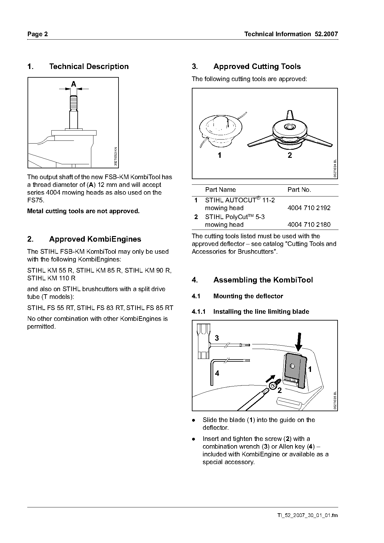
The output shaft of the new FSB-KM KombiTool has
a thread diameter of (A) 12 mm and will accept
series 4004 mowing heads as also used on the              Part Name                      Part No.
                                                                             ®
FS75.                                               1     STIHL AUTOCUT 11-2
Metal cutting tools are not approved.                     mowing head                    4004 710 2192
                                                    2     STIHL PolyCutTM 5-3
                                                          mowing head                    4004 710 2180
                                                    The cutting tools listed must be used with the
2.       Approved KombiEngines
                                                    approved deflector – see catalog "Cutting Tools and
The STIHL FSB-KM KombiTool may only be used         Accessories for Brushcutters".
with the following KombiEngines:
STIHL KM 55 R, STIHL KM 85 R, STIHL KM 90 R,
STIHL KM 110 R                                      4.       Assembling the KombiTool
and also on STIHL brushcutters with a split drive
tube (T models):                                    4.1      Mounting the deflector
STIHL FS 55 RT, STIHL FS 83 RT, STIHL FS 85 RT
                                                    4.1.1    Installing the line limiting blade
No other combination with other KombiEngines is
permitted.
                                                              3

                                                                                                1
                                                              4

                                                                                     2
                                                                                                         002TI035 BL

                                                    .     Slide the blade (1) into the guide on the
                                                          deflector.
                                                    .     Insert and tighten the screw (2) with a
                                                          combination wrench (3) or Allen key (4) –
                                                          included with KombiEngine or available as a
                                                          special accessory.

                                                                                     TI_52_2007_30_01_01.fm
Page 3 of 6
Text of page 3 — search, copy, screen readers
Technical Information 52.2007                                                                                           Page 3

4.1.2     Mounting the deflector


                                                        002TI036 BL
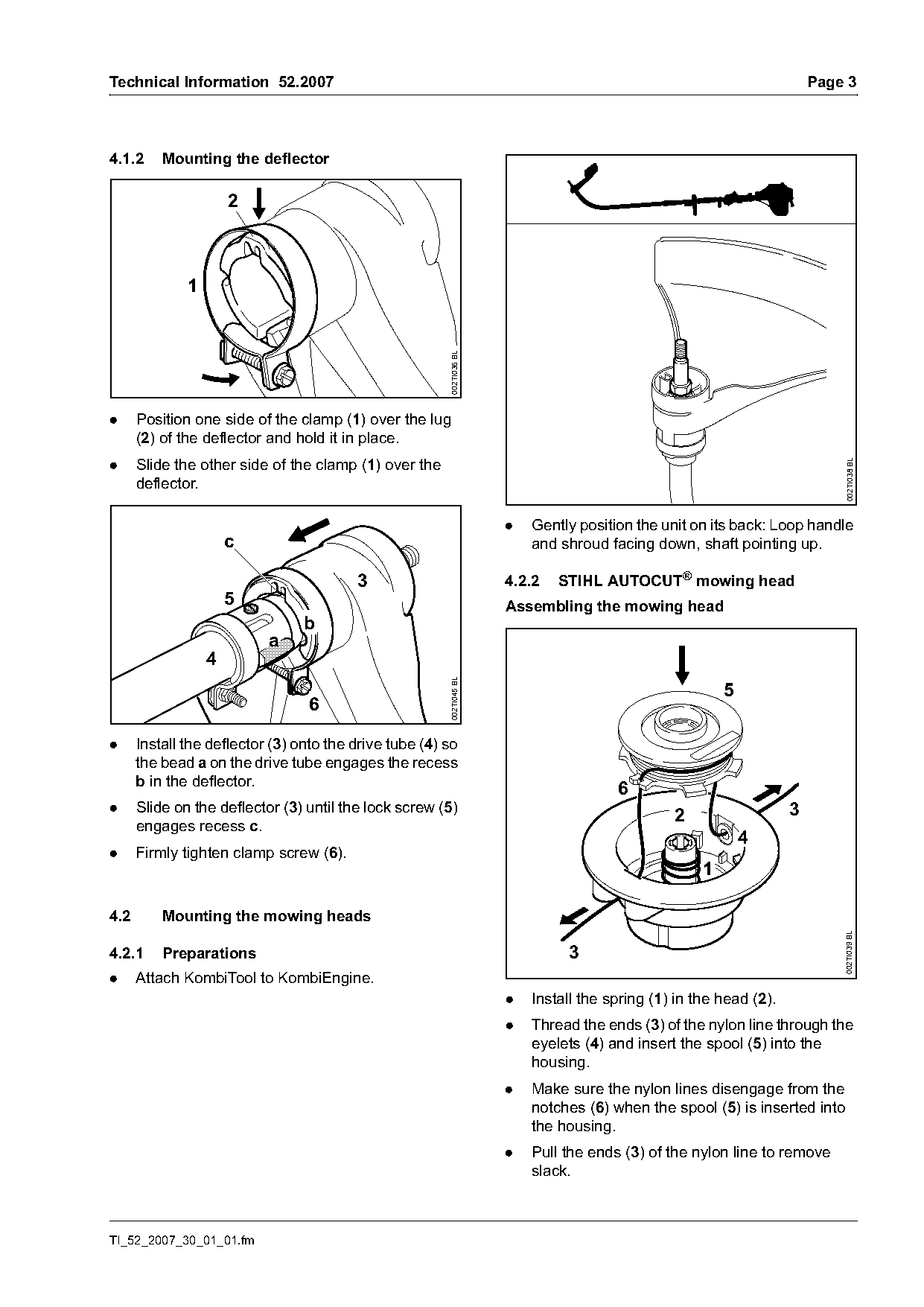
.     Position one side of the clamp (1) over the lug
      (2) of the deflector and hold it in place.
.     Slide the other side of the clamp (1) over the

                                                                                                                             002TI038 BL
      deflector.

                                                                      .   Gently position the unit on its back: Loop handle
                      c                                                   and shroud facing down, shaft pointing up.

                                         3                            4.2.2   STIHL AUTOCUT® mowing head
                      5                                               Assembling the mowing head
                                 b
                           a
                  4
                                                        002TI045 BL

                                                                                                         5
                                 6

.     Install the deflector (3) onto the drive tube (4) so
      the bead a on the drive tube engages the recess
      b in the deflector.
                                                                                       6
.     Slide on the deflector (3) until the lock screw (5)                                                           3
                                                                                                2
      engages recess c.
                                                                                                             4
.     Firmly tighten clamp screw (6).
                                                                                                     1

4.2       Mounting the mowing heads
                                                                                                                            002TI039 BL

4.2.1     Preparations                                                         3
.     Attach KombiTool to KombiEngine.
                                                                      .   Install the spring (1) in the head (2).
                                                                      .   Thread the ends (3) of the nylon line through the
                                                                          eyelets (4) and insert the spool (5) into the
                                                                          housing.
                                                                      .   Make sure the nylon lines disengage from the
                                                                          notches (6) when the spool (5) is inserted into
                                                                          the housing.
                                                                      .   Pull the ends (3) of the nylon line to remove
                                                                          slack.

TI_52_2007_30_01_01.fm
Page 4 of 6
Text of page 4 — search, copy, screen readers
Page 4                                                                               Technical Information 52.2007

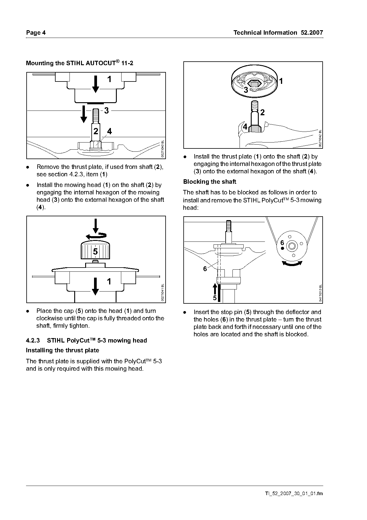
Mounting the STIHL AUTOCUT® 11-2

                               1                                                                         1
                                                                                         3

                              3                                                                 2
                                                                                         4
                          2 4

                                                                                                                        002TI042 BL
                                                    002TI040 BL
                                                                  .   Install the thrust plate (1) onto the shaft (2) by
.   Remove the thrust plate, if used from shaft (2),                  engaging the internal hexagon of the thrust plate
    see section 4.2.3, item (1)                                       (3) onto the external hexagon of the shaft (4).
                                                                  Blocking the shaft
.   Install the mowing head (1) on the shaft (2) by
    engaging the internal hexagon of the mowing                   The shaft has to be blocked as follows in order to
    head (3) onto the external hexagon of the shaft               install and remove the STIHL PolyCutTM 5-3 mowing
    (4).                                                          head:

                                                                                                         6
                          5
                                                                         6

                               1
                                                    002TI041 BL

                                                                                                                        541TI013 BL
                                                                             5
.   Place the cap (5) onto the head (1) and turn                  .   Insert the stop pin (5) through the deflector and
    clockwise until the cap is fully threaded onto the                the holes (6) in the thrust plate – turn the thrust
    shaft, firmly tighten.                                            plate back and forth if necessary until one of the
                                                                      holes are located and the shaft is blocked.
4.2.3    STIHL PolyCutTM 5-3 mowing head
Installing the thrust plate
The thrust plate is supplied with the PolyCutTM 5-3
and is only required with this mowing head.

                                                                                                    TI_52_2007_30_01_01.fm
Page 5 of 6
Text of page 5 — search, copy, screen readers
Technical Information 52.2007                                                                                       Page 5

                                                                    STIHL AUTOCUT® 11-2 mowing head

                                                                     Part Name                   Part No.
                                 7
                                                                     Mowing line,
                                                                     .080 in dia, green,
                                                                     different lengths           See catalog "Cutting
                                                                                                 Tools & Accessories for
                                                                     Mowing line,
                             8                                                                   Brushcutters and
                                                                     .095 in dia, orange,
                                                                                                 Trimmers"
                                                                     different lengths
                                                                     Prewound spool

                             2
                                                                    STIHL PolyCutTM 5-3 mowing head

                                                                     Part Name                   Part No.
                                                                     Blades (plastic;
                                                      002TI044 BL

                                                                     pack of 12)                 4111 007 1001
                                                                     Thrust plate                4130 713 1501
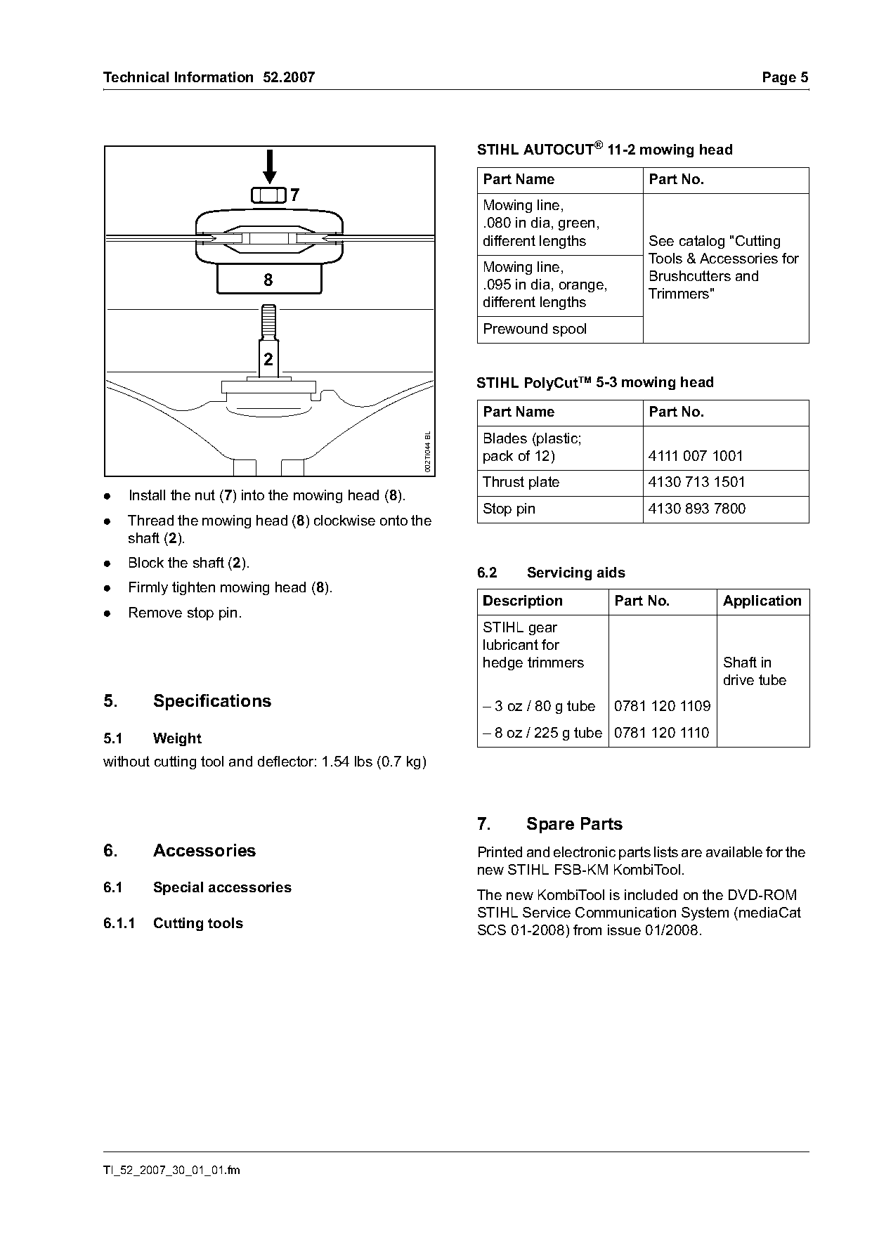
.     Install the nut (7) into the mowing head (8).
                                                                     Stop pin                    4130 893 7800
.     Thread the mowing head (8) clockwise onto the
      shaft (2).
.     Block the shaft (2).
                                                                    6.2     Servicing aids
.     Firmly tighten mowing head (8).
                                                                     Description            Part No.         Application
.     Remove stop pin.
                                                                     STIHL gear
                                                                     lubricant for
                                                                     hedge trimmers                          Shaft in
                                                                                                             drive tube
5.        Specifications                                             – 3 oz / 80 g tube     0781 120 1109

5.1       Weight                                                     – 8 oz / 225 g tube 0781 120 1110

without cutting tool and deflector: 1.54 lbs (0.7 kg)

                                                                    7.      Spare Parts
6.        Accessories                                               Printed and electronic parts lists are available for the
                                                                    new STIHL FSB-KM KombiTool.
6.1       Special accessories                                       The new KombiTool is included on the DVD-ROM
                                                                    STIHL Service Communication System (         6.1.1     Cutting tools                                             SCS 01-2008) from issue 01/2008.

TI_52_2007_30_01_01.fm
Page 6 of 6
Text of page 6 — search, copy, screen readers
Page 6                                                                Technical Information 52.2007

8.       Repairs
If the complete machine is started up in the course
of repairs, it is essential to observe all safety
regulations and safety precautions outlined in the
FSB-KM KombiTool instruction manual and the
instruction manual of the KombiEngine that is being
used.

8.1      Service Manuals
The KombiTools service manual is available for
servicing and repair procedures on the FSB-KM
KombiTool.

8.2      Repair times
The repair times specified for the FS 75 drive tube
may be used for the new STIHL FSB-KM
KombiTool.
The specified repair times assume that the work is
performed by trained personnel in a properly
equipped service workshop.

© ANDREAS STIHL AG & Co. KG, 2007                     Technical Documentation
                                                      D1/MTK-na

                                                                                TI_52_2007_30_01_01.fm
Most of these PDFs embed fonts with a shifted character map, so the text above was recovered rather than copied — read it as a faithful but imperfect transcription, and treat the page image above each block as the authority where the two disagree — the figures exist only there, because they are vector drawings that text extraction cannot keep.