Technical Information · issue 62 of 2007
New STIHL BG-KM CombiTool
IssueTI 62/2007
Full text
Page 1 of 3
Text of page 1 — search, copy, screen readers
STIH)

Technical Information                                 62.2007

  New STIHL BG-KM KombiTool – Series 4606

  Contents
  1.   BG-KM Blower KombiTool
  2.   Technical Description
  3.   Approved KombiEngines
  4.   Assembling the KombiTool
  5.   Specifications
  6.   Special Accessory for Users
  7.   Service Accessories
  8.   Spare Parts
  9.   Repairs

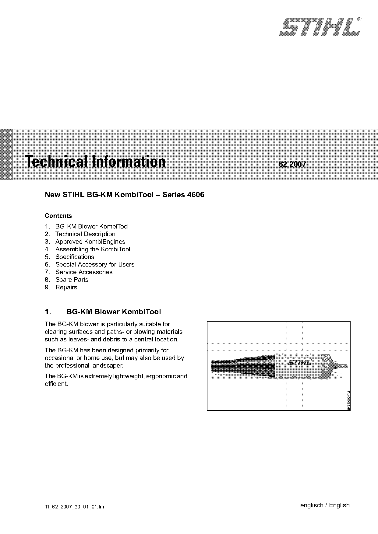
  1.      BG-KM Blower KombiTool
  The BG-KM blower is particularly suitable for
  clearing surfaces and paths- or blowing materials
  such as leaves- and debris to a central location.
  The BG-KM has been designed primarily for
  occasional or home use, but may also be used by
  the professional landscaper.
  The BG-KM is extremely lightweight, ergonomic and
  efficient.

  TI_62_2007_30_01_01.fm                                   englisch / English
Page 2 of 3
Text of page 2 — search, copy, screen readers
Page 2                                                                    Technical Information 62.2007

2.       Technical Description                          Only operate blower with a properly installed blower
                                                        tube.
The BG-KM is a multi-stage axial blower.
Depending on the KombiEngine used, the blower’s
performance may vary.
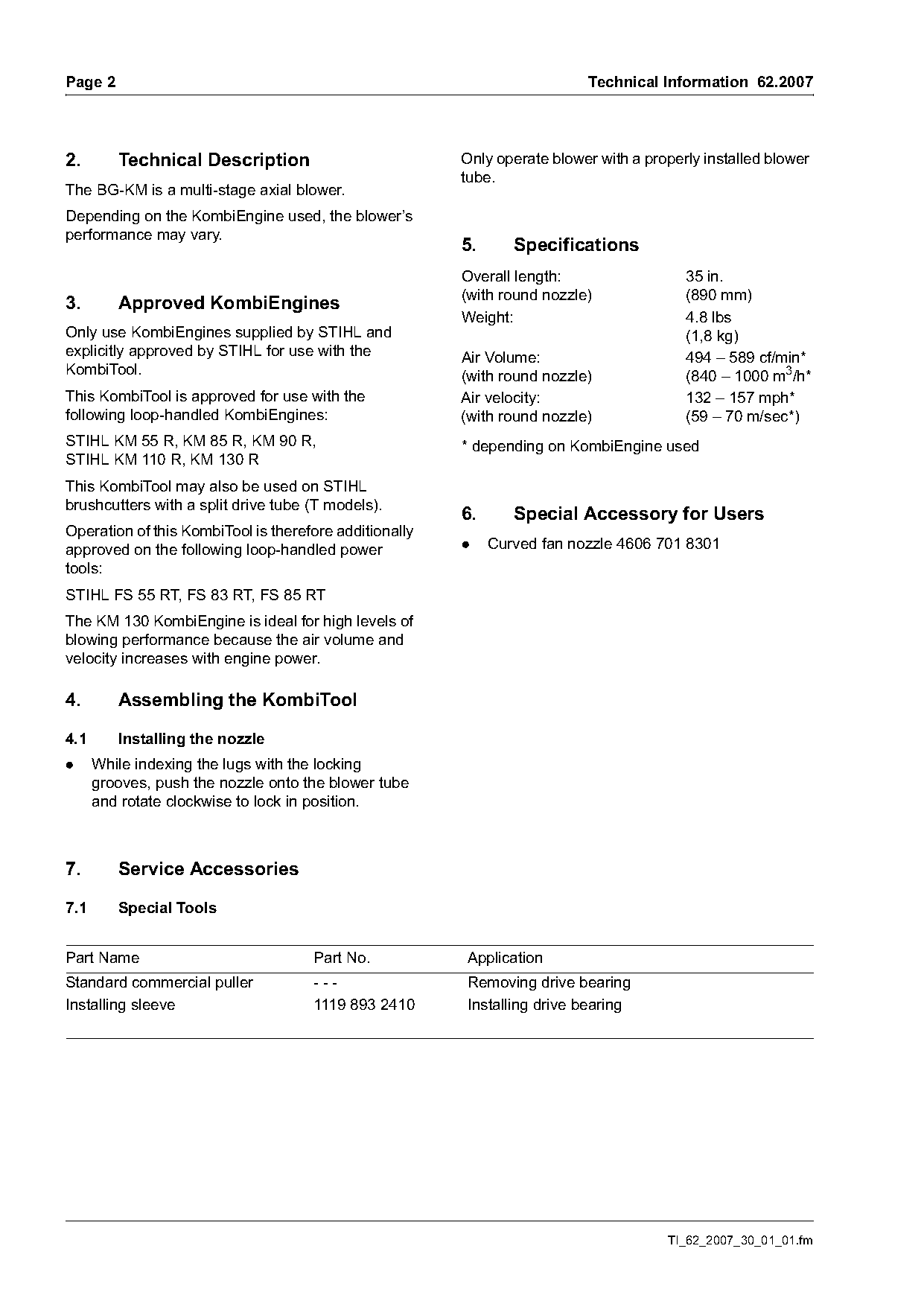
                                                        5.      Specifications
                                                        Overall length:                  35 in.
                                                        (with round nozzle)              (890 mm)
3.       Approved KombiEngines
                                                        Weight:                          4.8 lbs
Only use KombiEngines supplied by STIHL and                                              (1,8 kg)
explicitly approved by STIHL for use with the           Air Volume:                      494 – 589 cf/min*
KombiTool.                                              (with round nozzle)              (840 – 1000 m3/h*
This KombiTool is approved for use with the             Air velocity:                    132 – 157 mph*
following loop-handled KombiEngines:                    (with round nozzle)              (59 – 70 m/sec*)
STIHL KM 55 R, KM 85 R, KM 90 R,                        * depending on KombiEngine used
STIHL KM 110 R, KM 130 R
This KombiTool may also be used on STIHL
brushcutters with a split drive tube (T models).
                                                        6.      Special Accessory for Users
Operation of this KombiTool is therefore additionally
approved on the following loop-handled power            .    Curved fan nozzle 4606 701 8301
tools:
STIHL FS 55 RT, FS 83 RT, FS 85 RT
The KM 130 KombiEngine is ideal for high levels of
blowing performance because the air volume and
velocity increases with engine power.

4.       Assembling the KombiTool

4.1      Installing the nozzle
.     While indexing the lugs with the locking
      grooves, push the nozzle onto the blower tube
      and rotate clockwise to lock in position.

7.       Service Accessories

7.1      Special Tools

Part Name                            Part No.           Application
Standard commercial puller           ---                Removing drive bearing
Installing sleeve                    1119 893 2410      Installing drive bearing

                                                                                      TI_62_2007_30_01_01.fm
Page 3 of 3
Text of page 3 — search, copy, screen readers
Technical Information 62.2007                                                                               Page 3

8.      Spare Parts                                         9.2       Drive bearing

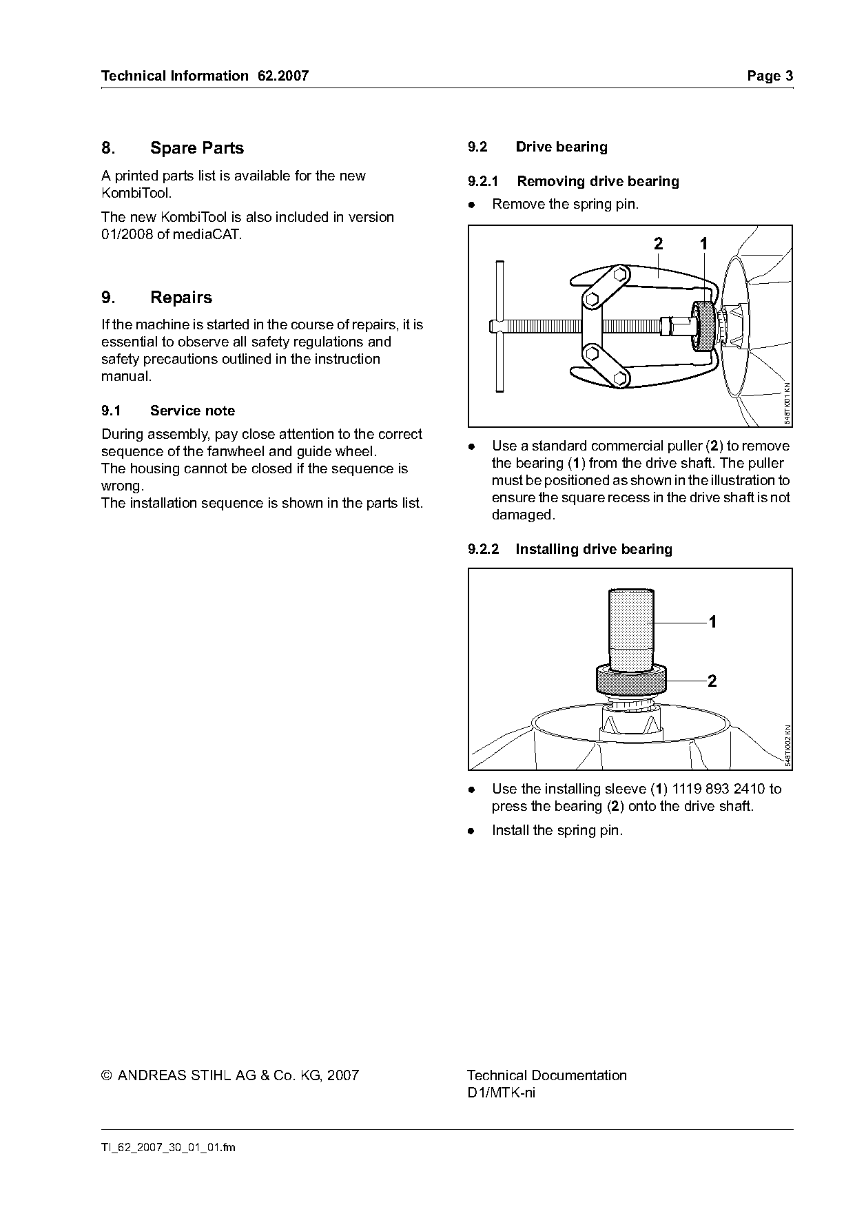
A printed parts list is available for the new               9.2.1     Removing drive bearing
KombiTool.
                                                            .     Remove the spring pin.
The new KombiTool is also included in version
01/2008 of         .
                                                                                             2      1

9.      Repairs
If the machine is started in the course of repairs, it is
essential to observe all safety regulations and
safety precautions outlined in the instruction
manual.

                                                                                                                   548TI001 KN
9.1     Service note
During assembly, pay close attention to the correct
sequence of the fanwheel and guide wheel.                   .     Use a standard commercial puller (2) to remove
The housing cannot be closed if the sequence is                   the bearing (1) from the drive shaft. The puller
wrong.                                                            must be positioned as shown in the illustration to
The installation sequence is shown in the parts list.             ensure the square recess in the drive shaft is not
                                                                  damaged.

                                                            9.2.2     Installing drive bearing


                                                            .     Use the installing sleeve (1) 1119 893 2410 to    548TI002 KN

                                                                  press the bearing (2) onto the drive shaft.
                                                            .     Install the spring pin.

© ANDREAS STIHL AG & Co. KG, 2007                           Technical Documentation
                                                            D1/MTK-ni

TI_62_2007_30_01_01.fm
Most of these PDFs embed fonts with a shifted character map, so the text above was recovered rather than copied — read it as a faithful but imperfect transcription, and treat the page image above each block as the authority where the two disagree — the figures exist only there, because they are vector drawings that text extraction cannot keep.