Technical Information · issue 64 of 2007
Carburetor; Fuel tank; Filter cover; Easy2Start™; Pleated filter system; Flywheel; Catcher blade; Blade clearance adjuster kit; Summary
IssueTI 64/2007
Part changes (5)
| Was | Becomes | What the bulletin says |
|---|---|---|
| 4237 120 0601 | 4237 120 0604 | Carburetor The previous carburetor 4237 120 0601 with smooth connector will be replaced by the new carburetor 4237 120 0604 with barbed connector. |
| 4237 120 2200 | 4237 120 2202 | The previous flange 4237 120 2200 with smooth connector will be replaced by the new flange 4237 120 2202 with barbed connector. |
| 4229 122 6801 | 4237 122 6800 | The previous low speed adjustment screw 4229 122 6801 will be replaced by the new low speed adjustment screw 4237 122 6800. |
| 4282 350 1400 | 4237 350 1400 | 1 Connector The previous connector 4282 350 1400 will be replaced by the new connector 4237 350 1400. |
| 4237 140 1000 | 4237 140 1003 | Flywheel The previous filter cover 4237 140 1000 (for The new flywheel 4237 400 1202 can be used with standard filters) will be replaced by new filter cover the standard rewind starter or the new Easy2Start™ 4237 140 1003. |
Full text
Page 1 of 7
Text of page 1 — search, copy, screen readers
STIH)

Technical Information                                                              64.2007

  Hedge trimmers STIHL HS 81 R, HS 81 T                           – Series 4237
  Hedge trimmers STIHL HS 86 R, HS 86 T                           – Series 4237

  Contents
  1.   Carburetor
  2.   Fuel tank
  3.   Filter cover
  4.   Easy2Start™
  5.   Pleated filter system
  6.   Flywheel
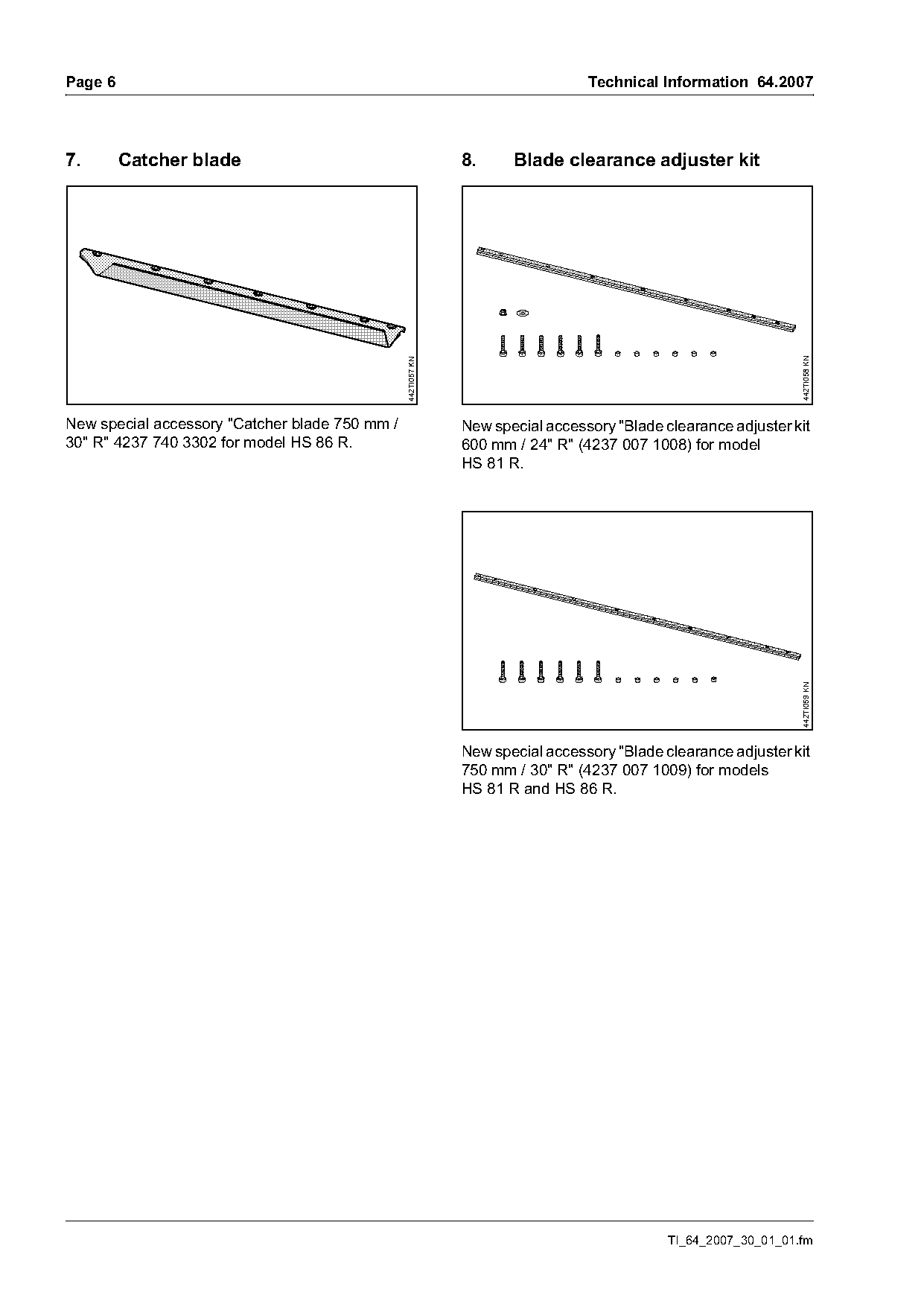
  7.   Catcher blade
  8.   Blade clearance adjuster kit
  9.   Summary

  1.      Carburetor
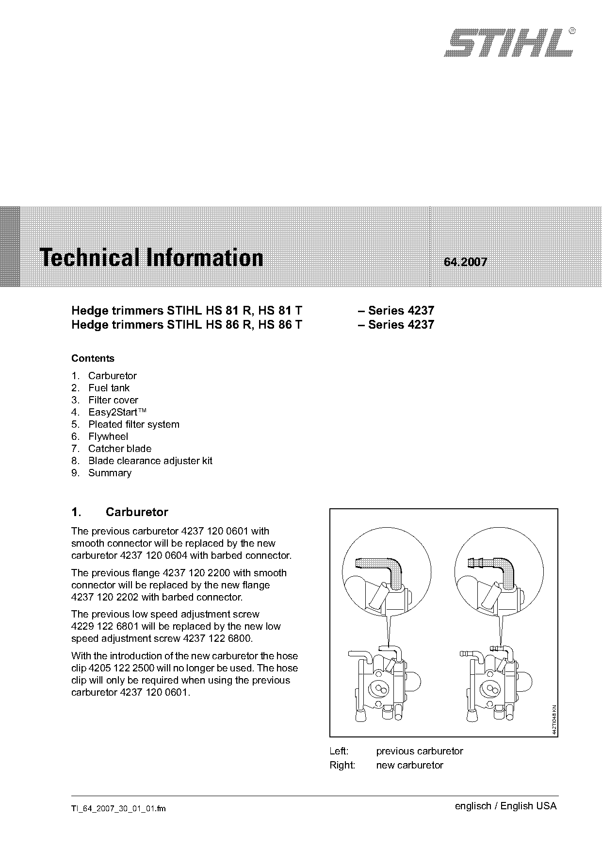
  The previous carburetor 4237 120 0601 with
  smooth connector will be replaced by the new
  carburetor 4237 120 0604 with barbed connector.
  The previous flange 4237 120 2200 with smooth
  connector will be replaced by the new flange
  4237 120 2202 with barbed connector.
  The previous low speed adjustment screw
  4229 122 6801 will be replaced by the new low
  speed adjustment screw 4237 122 6800.
  With the introduction of the new carburetor the hose
  clip 4205 122 2500 will no longer be used. The hose
  clip will only be required when using the previous
  carburetor 4237 120 0601.
                                                                                                          442TI048 KN

                                                         Left:       previous carburetor
                                                         Right:      new carburetor

  TI_64_2007_30_01_01.fm                                                              englisch / English USA
Page 2 of 7
Text of page 2 — search, copy, screen readers
Page 2                                                                                 Technical Information 64.2007

1.1      Supply of spare parts                                     1.3      Service note
Only the new carburetor will be available as a spare               To ensure that there are no leaks in the fuel system:
part.
                                                                   .     Fuel hoses should only be disconnected and
When the previous carburetor or previous flange is                       installed by hand in order to avoid damaging the
replaced by a new carburetor or new flange, the fuel                     barbed connector. Sharp-edged pliers,
return hose must be shortened to 6.70 in (170 mm).                       screwdrivers, etc. must not be used – nor should
An illustrated supplement with installation                              fuel hoses be cut open with a knife or similar
instructions will be enclosed with the new carburetor                    implement.
and flange.
                                                                   .     Fuel hoses must not be reused after being
                                                                         disconnected. They must always be replaced by
1.2      Installation of the fuel return hose
                                                                         new hoses. Fuel hoses may be over-extended
                                                                         when disconnected.
                                                                   .     New fuel hoses must be installed in a dry
                                                                         condition or with the aid of Press Fluid OH 723
                                                                         – 0781 957 9000.
                                                                   .     When using Press Fluid OH 723, coat the ends
                                                                         of hoses and connectors with Press Fluid
                                                                         OH 723 prior to installing the new hoses onto
                                                                         the barbed connectors.
                                                     442TI049 KN

                                                                   Note concerning Press Fluid OH 723
                                                                   Press Fluid OH 723 creates a lubricant film to aid in
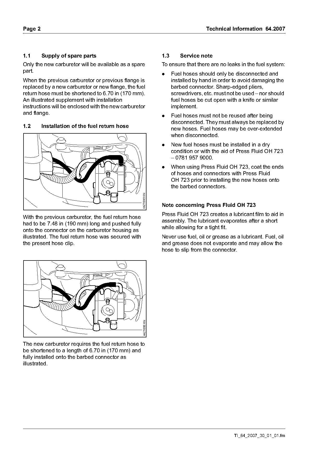
With the previous carburetor, the fuel return hose
                                                                   assembly. The lubricant evaporates after a short
had to be 7.48 in (190 mm) long and pushed fully
                                                                   while allowing for a tight fit.
onto the connector on the carburetor housing as
illustrated. The fuel return hose was secured with                 Never use fuel, oil or grease as a lubricant. Fuel, oil
the present hose clip.                                             and grease does not evaporate and may allow the
                                                                   hose to slip from the connector.
                                                     442TI050 KN

The new carburetor requires the fuel return hose to
be shortened to a length of 6.70 in (170 mm) and
fully installed onto the barbed connector as
illustrated.

                                                                                                   TI_64_2007_30_01_01.fm
Page 3 of 7
Text of page 3 — search, copy, screen readers
Technical Information 64.2007                                                                                     Page 3

2.      Fuel tank                                                   2.1.1   Removing the previous connector

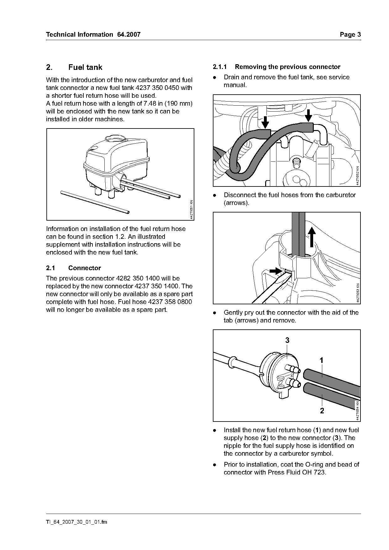
With the introduction of the new carburetor and fuel                .   Drain and remove the fuel tank, see service
tank connector a new fuel tank 4237 350 0450 with                       manual.
a shorter fuel return hose will be used.
A fuel return hose with a length of 7.48 in (190 mm)
will be enclosed with the new tank so it can be
installed in older machines.

                                                                                                                        442TI052 KN
                                                                    .   Disconnect the fuel hoses from the carburetor
                                                                        (arrows).
                                                      442TI051 KN

Information on installation of the fuel return hose
can be found in section 1.2. An illustrated
supplement with installation instructions will be
enclosed with the new fuel tank.

2.1     Connector
The previous connector 4282 350 1400 will be
replaced by the new connector 4237 350 1400. The

                                                                                                                        442TI053 KN
new connector will only be available as a spare part
complete with fuel hose. Fuel hose 4237 358 0800
will no longer be available as a spare part.                        .   Gently pry out the connector with the aid of the
                                                                        tab (arrows) and remove.


                                                                                                           1
                                                                                                                        442TI054 KN


                                                                    .   Install the new fuel return hose (1) and new fuel
                                                                        supply hose (2) to the new connector (3). The
                                                                        nipple for the fuel supply hose is identified on
                                                                        the connector by a carburetor symbol.
                                                                    .   Prior to installation, coat the O-ring and bead of
                                                                        connector with Press Fluid OH 723.

TI_64_2007_30_01_01.fm
Page 4 of 7
Text of page 4 — search, copy, screen readers
Page 4                                                                               Technical Information 64.2007

2.1.2    Installing the new connector                             2.1.3   Testing the fuel tank for leaks


                                                                                                                       442TI046 KN
                                                                                        1             2

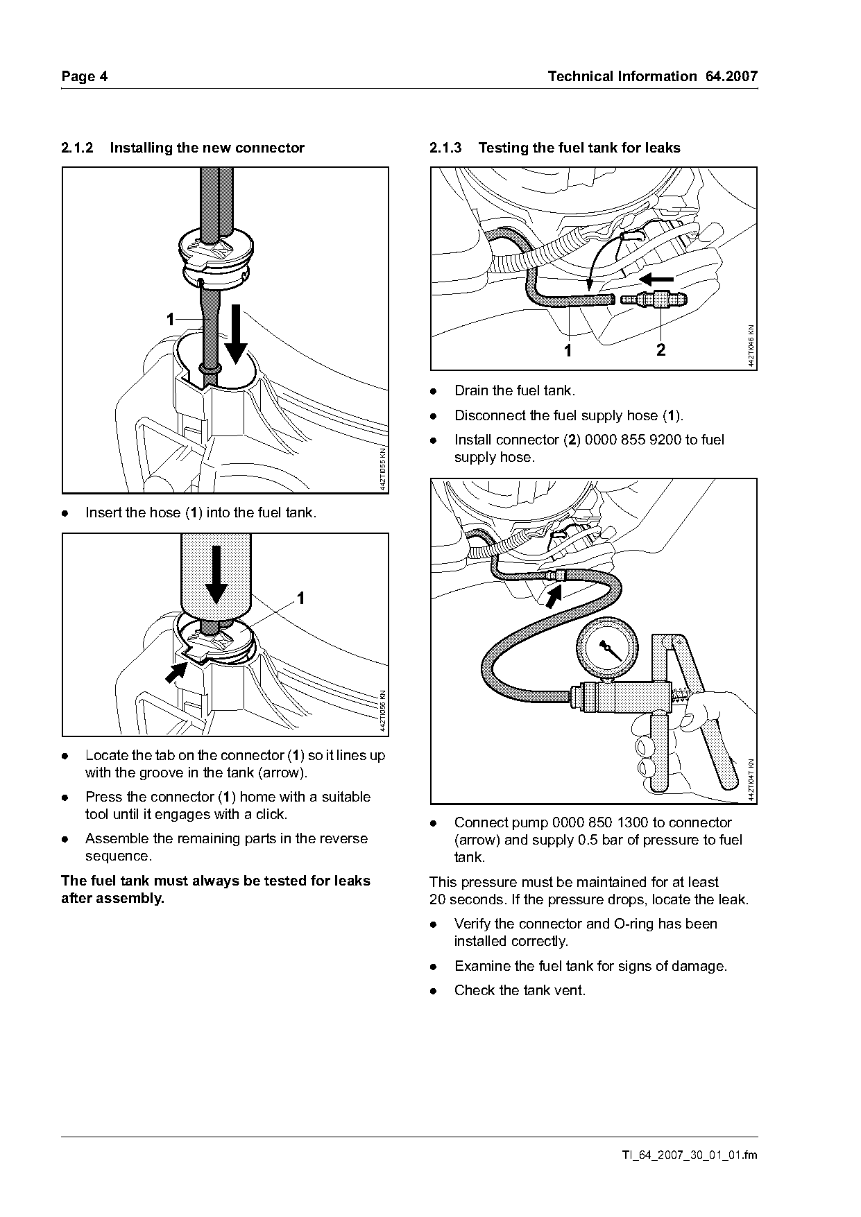
                                                                  .   Drain the fuel tank.
                                                                  .   Disconnect the fuel supply hose (1).
                                                                  .   Install connector (2) 0000 855 9200 to fuel
                                                    442TI055 KN

                                                                      supply hose.

.   Insert the hose (1) into the fuel tank.

                                       1
                                                    442TI056 KN

.   Locate the tab on the connector (1) so it lines up                                                                 442TI047 KN

    with the groove in the tank (arrow).
.   Press the connector (1) home with a suitable
    tool until it engages with a click.
                                                                  .   Connect pump 0000 850 1300 to connector
.   Assemble the remaining parts in the reverse                       (arrow) and supply 0.5 bar of pressure to fuel
    sequence.                                                         tank.
The fuel tank must always be tested for leaks                     This pressure must be maintained for at least
after assembly.                                                   20 seconds. If the pressure drops, locate the leak.
                                                                  .   Verify the connector and O-ring has been
                                                                      installed correctly.
                                                                  .   Examine the fuel tank for signs of damage.
                                                                  .   Check the tank vent.

                                                                                                TI_64_2007_30_01_01.fm
Page 5 of 7

Text of page 5 — search, copy, screen readers
Technical Information 64.2007                                                                       Page 5

3.      Filter cover                                     6.     Flywheel
The previous filter cover 4237 140 1000 (for             The new flywheel 4237 400 1202 can be used with
standard filters) will be replaced by new filter cover   the standard rewind starter or the new Easy2Start™
4237 140 1003.                                           system.

4.      Easy2Start™

4.1     New model STIHL HS 81 TCE
The new model STIHL HS 81 TCE (Easy2Start™)
will use a new fan housing with rewind starter
4234 080 2104 and new flywheel 4237 400 1202.
The new fan housing with rewind starter may only
be installed in machines with the new flywheel
4237 400 1202.

See spare parts list for further details.                The flywheel has two threaded domes so it can be
                                                         removed with puller 1135 890 4500.
4.2     Service note
When servicing the starter assembly, coat the post
of the rope rotor, pawl spring and peg of the pawls
with grease 0781 120 1111.
PLEASE NOTE:
The rewind spring for the starter rope may pop out
of position during disassembly.

5.      Pleated filter system

5.1     New model STIHL HS 81 TCE
The new model STIHL HS 81 TCE (Easy2Start™)
will also use a new pleated filter system which will
include a new filter housing 4237 140 2802,
grommet 4134 123 7500, filter cover
4237 140 1002, air filter 4237 141 0300 and a new
carburetor with compensator 4237 120 0606 and
barbed flange 4237 120 2201.

TI_64_2007_30_01_01.fm
Page 6 of 7
Text of page 6 — search, copy, screen readers
Page 6                                                                          Technical Information 64.2007

7.       Catcher blade                                        8.     Blade clearance adjuster kit

                                                                                                                442TI058 KN
                                                442TI057 KN
New special accessory "Catcher blade 750 mm /                 New special accessory "Blade clearance adjuster kit
30" R" 4237 740 3302 for model HS 86 R.                       600 mm / 24" R" (4237 007 1008) for model
                                                              HS 81 R.

                                                                                                                442TI059 KN
                                                              New special accessory "Blade clearance adjuster kit
                                                              750 mm / 30" R" (4237 007 1009) for models
                                                              HS 81 R and HS 86 R.

                                                                                            TI_64_2007_30_01_01.fm
Page 7 of 7
Text of page 7 — search, copy, screen readers
Technical Information 64.2007                                                                      Page 7

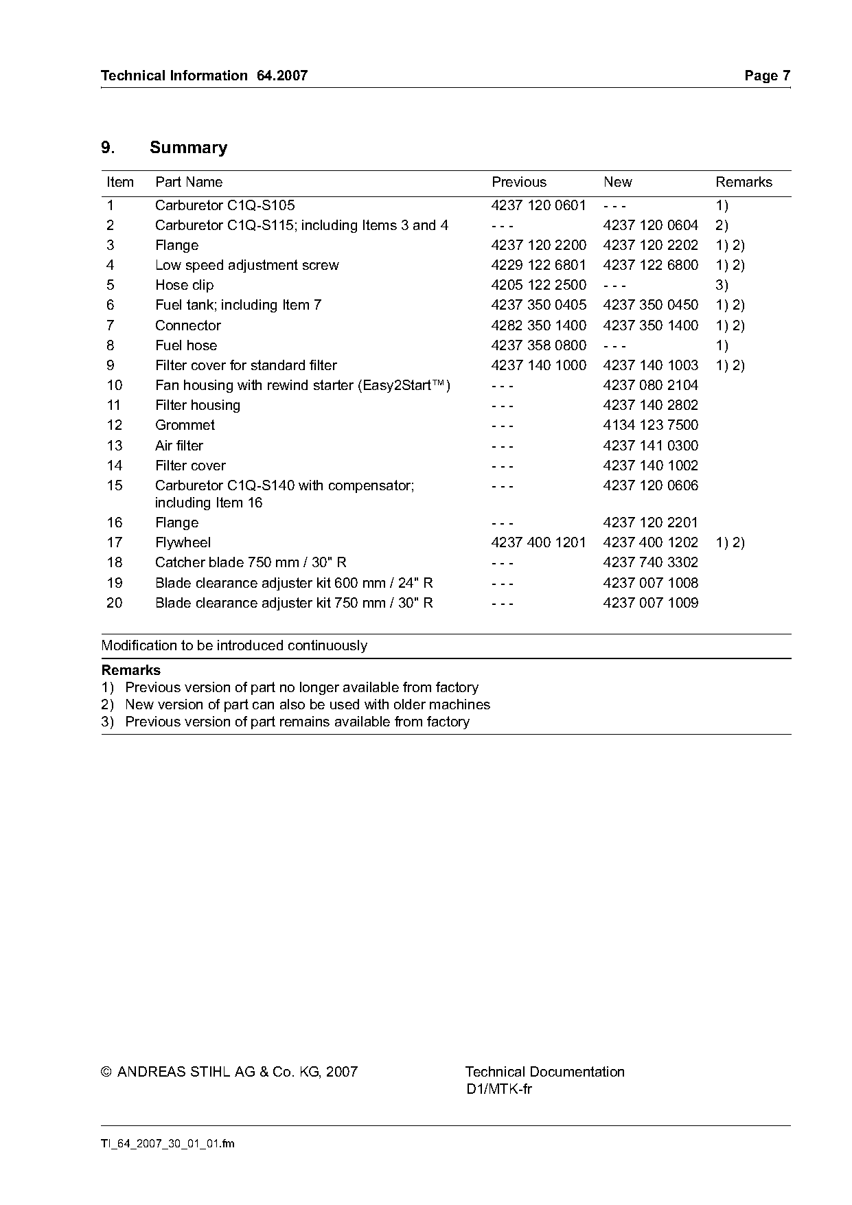
9.     Summary
Item    Part Name                                              Previous        New             Remarks
1       Carburetor C1Q-S105                                    4237 120 0601   ---             1)
2       Carburetor C1Q-S115; including Items 3 and 4           ---             4237 120 0604   2)
3       Flange                                                 4237 120 2200   4237 120 2202   1) 2)
4       Low speed adjustment screw                             4229 122 6801   4237 122 6800   1) 2)
5       Hose clip                                              4205 122 2500   ---             3)
6       Fuel tank; including Item 7                            4237 350 0405   4237 350 0450   1) 2)
7       Connector                                              4282 350 1400   4237 350 1400   1) 2)
8       Fuel hose                                              4237 358 0800   ---             1)
9       Filter cover for standard filter                       4237 140 1000   4237 140 1003   1) 2)
10      Fan housing with rewind starter (Easy2Start™)          ---             4237 080 2104
11      Filter housing                                         ---             4237 140 2802
12      Grommet                                                ---             4134 123 7500
13      Air filter                                             ---             4237 141 0300
14      Filter cover                                           ---             4237 140 1002
15      Carburetor C1Q-S140 with compensator;                  ---             4237 120 0606
        including Item 16
16      Flange                                                 ---             4237 120 2201
17      Flywheel                                               4237 400 1201   4237 400 1202   1) 2)
18      Catcher blade 750 mm / 30" R                           ---             4237 740 3302
19      Blade clearance adjuster kit 600 mm / 24" R            ---             4237 007 1008
20      Blade clearance adjuster kit 750 mm / 30" R            ---             4237 007 1009

Modification to be introduced continuously
Remarks
1) Previous version of part no longer available from factory
2) New version of part can also be used with older machines
3) Previous version of part remains available from factory

© ANDREAS STIHL AG & Co. KG, 2007                       Technical Documentation
                                                        D1/MTK-fr

TI_64_2007_30_01_01.fm
Most of these PDFs embed fonts with a shifted character map, so the text above was recovered rather than copied — read it as a faithful but imperfect transcription, and treat the page image above each block as the authority where the two disagree — the figures exist only there, because they are vector drawings that text extraction cannot keep.