Technical Information · issue 1 of 2008
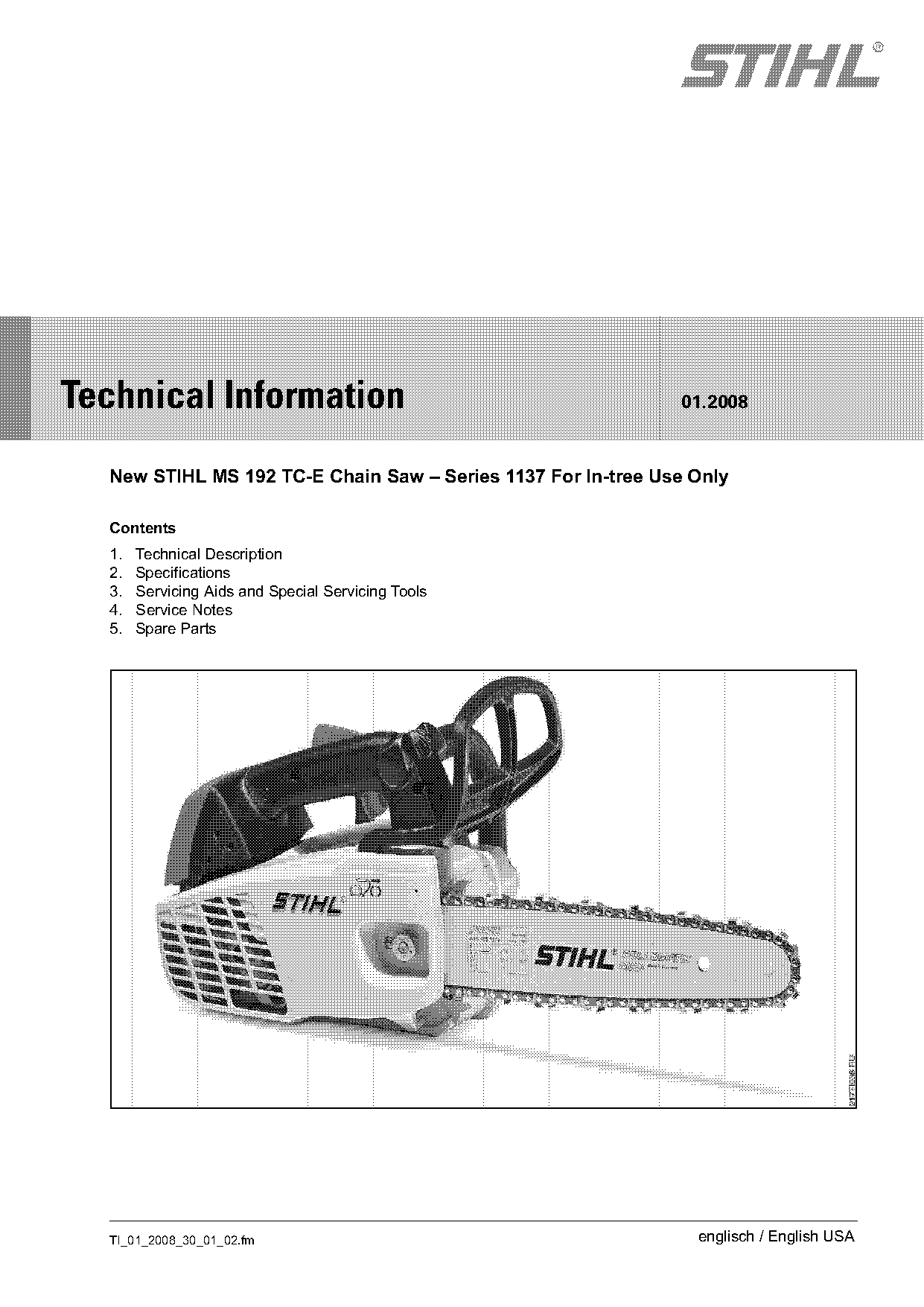
New STIHL MS 192 TC-E Chain Saw
IssueTI 1/2008
Engine family 1137
Full text
Page 1 of 13
Text of page 1 — search, copy, screen readers
STIH)

Technical Information                                         01.2008

  New STIHL MS 192 TC-E Chain Saw – Series 1137 For In-tree Use Only

  Contents
  1.   Technical Description
  2.   Specifications
  3.   Servicing Aids and Special Servicing Tools
  4.   Service Notes
  5.   Spare Parts

  TI_01_2008_30_01_02.fm                                        englisch / English USA
Page 2 of 13
Text of page 2 — search, copy, screen readers
Page 2                                                                      Technical Information 01.2008

The new version of the STIHL MS 192 TC-E chain        1.        Technical Description
saw with Easy2StartTM is tailored for professional
tree care.                                            1.1       Engine
The STIHL MS 192 TC-E features:                       STIHL single cylinder two-stroke engine
.   Easy2StartTM                                      Cylinder
.   Toolless filler caps                              .     Four-port system for optimum performance.
.   Transparent tanks
.   Manual purge primer                               Piston
.   Side chain tensioner                              .     Two piston rings for optimum performance over
                                                            a long service life
.   Microprocessor controlled ignition system for
    smooth starts
Even with its light weight, the STIHL MS 192 TC-E     Crankshaft
offers powerful torque. The accelerator pump in the   .     Lightweight, durable five-piece crankshaft
carburetor and the microprocessor-controlled
ignition system are designed to provide fast
acceleration and generate a clean cut.                Carburetor
Along with the compact design, the MS 192 TC-E is     .     Diaphragm carburetor with full throttle semi-
easy to service. All service-related components are         fixed jet, idle fixed jet and premixture control.
accessible in a few easy steps.
                                                      .     The adjustment range of the high speed screw
                                                            is limited by a limiter cap (approx. 3/4 turn). This
                                                            limitation ensures safe operation and
                                                            maintenance of future exhaust emission levels.
                                                      .     Accelerator pump for fast and spontaneous
                                                            acceleration.

                                                      Ignition System
                                                      .     Microprocessor-controlled ignition system with
                                                            ignition timing adjustment for stable idling,
                                                            smooth starting, and optimum performance and
                                                            torque.

                                                                                         TI_01_2008_30_01_02.fm
Page 3 of 13
Text of page 3 — search, copy, screen readers
Technical Information 01.2008                                                                              Page 3

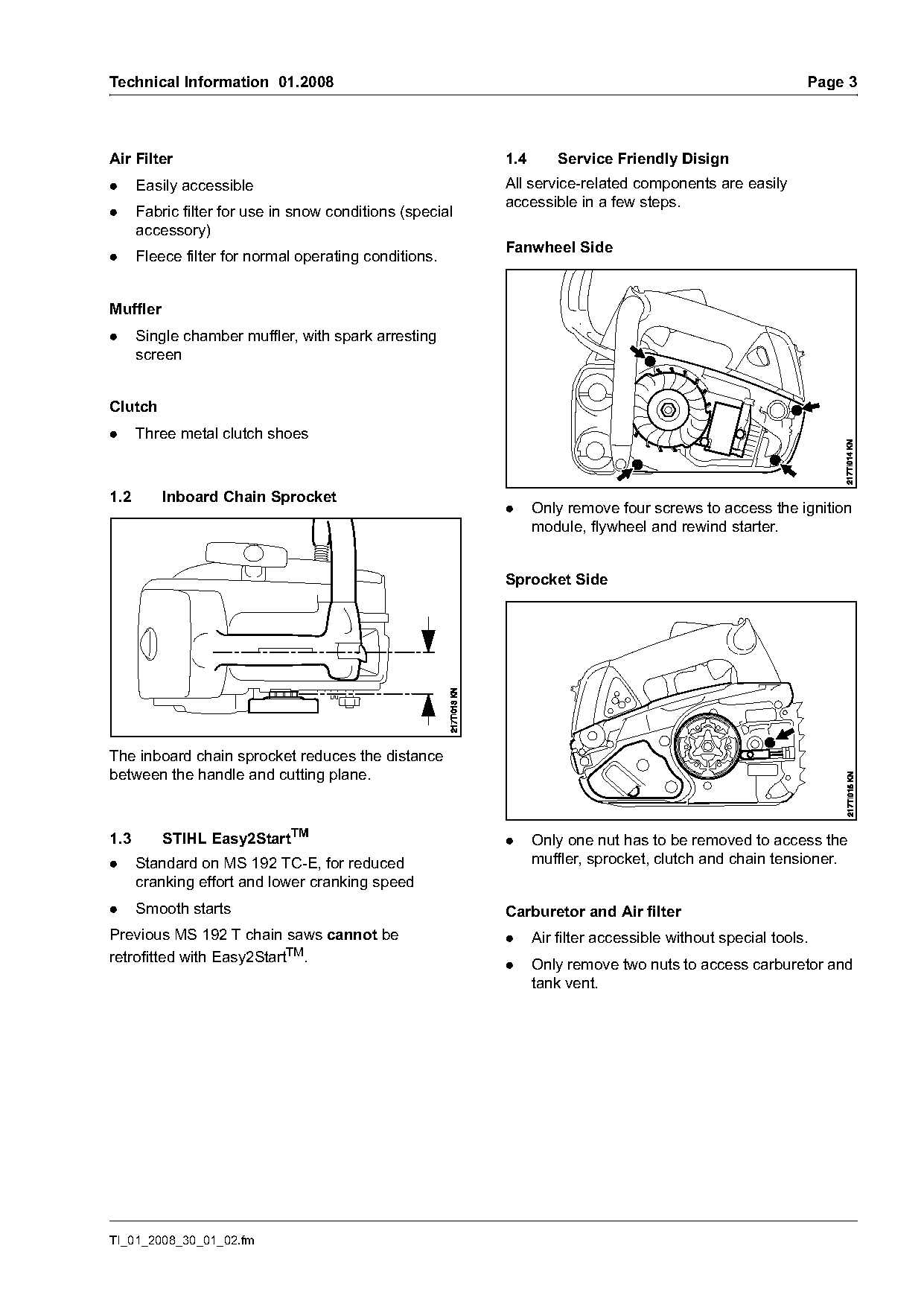
Air Filter                                                1.4       Service Friendly Disign
.     Easily accessible                                   All service-related components are easily
                                                          accessible in a few steps.
.     Fabric filter for use in snow conditions (special
      accessory)
                                                          Fanwheel Side
.     Fleece filter for normal operating conditions.

Muffler
.     Single chamber muffler, with spark arresting
      screen

Clutch
.     Three metal clutch shoes

1.2       Inboard Chain Sprocket
                                                          .     Only remove four screws to access the ignition
                                                                module, flywheel and rewind starter.

                                                          Sprocket Side

The inboard chain sprocket reduces the distance
between the handle and cutting plane.

1.3       STIHL Easy2StartTM                              .     Only one nut has to be removed to access the
.     Standard on MS 192 TC-E, for reduced                      muffler, sprocket, clutch and chain tensioner.
      cranking effort and lower cranking speed
.     Smooth starts                                       Carburetor and Air filter
Previous MS 192 T chain saws cannot be                    .     Air filter accessible without special tools.
retrofitted with Easy2StartTM.                            .     Only remove two nuts to access carburetor and
                                                                tank vent.

TI_01_2008_30_01_02.fm
Page 4 of 13
Text of page 4 — search, copy, screen readers
Page 4                                                                     Technical Information 01.2008

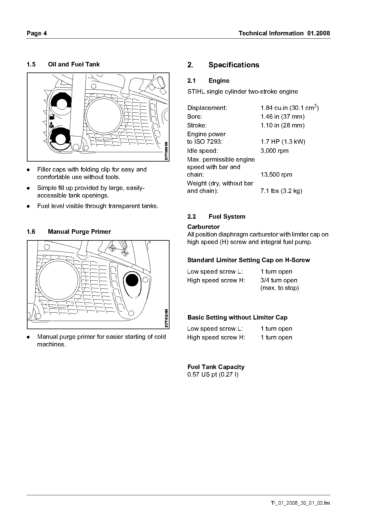
1.5       Oil and Fuel Tank                             2.      Specifications

                                                        2.1     Engine
                                                        STIHL single cylinder two-stroke engine

                                                        Displacement:              1.84 cu.in (30.1 cm3)
                                                        Bore:                      1.46 in (37 mm)
                                                        Stroke:                    1.10 in (28 mm)
                                                        Engine power
                                                        to ISO 7293:               1.7 HP (1.3 kW)
                                                        Idle speed:                3,000 rpm
                                                        Max. permissible engine
.     Filler caps with folding clip for easy and        speed with bar and
      comfortable use without tools.                    chain:                     13,500 rpm
                                                        Weight (dry, without bar
.     Simple fill up provided by large, easily-         and chain):                7.1 lbs (3.2 kg)
      accessible tank openings.
.     Fuel level visible through transparent tanks.
                                                        2.2     Fuel System
                                                        Carburetor
1.6       Manual Purge Primer                           All position diaphragm carburetor with limiter cap on
                                                        high speed (H) screw and integral fuel pump.

                                                        Standard Limiter Setting Cap on H-Screw
                                                        Low speed screw L:         1 turn open
                                                        High speed screw H:        3/4 turn open
                                                                                   (max. to stop)

                                                        Basic Setting without Limiter Cap
                                                        Low speed screw L:         1 turn open
.     Manual purge primer for easier starting of cold   High speed screw H:        1 turn open
      machines.

                                                        Fuel Tank Capacity
                                                        0.57 US pt (0.27 l)

                                                                                       TI_01_2008_30_01_02.fm
Page 5 of 13
Text of page 5 — search, copy, screen readers
Technical Information 01.2008                        Page 5

2.3     Ignition System
Ignition module:         microprocessor-
                         controlled with
                         automatic adjustment of
                         the ignition timing.
Spark plug (suppressed): NGK BPMR 7 A
Electrode gap:           .020 in (0.5 mm)

2.4     Chain Lubrication
Oil pump:                 Speed-dependent, fully
                          automatic with rotary
                          piston
Oil tank capacity:        0.46 US pt (0.22 l)

2.5     Recommended Cutting Attachments
Only use low kickback chain.
Guide bars:               ROLLOMATIC® Mini
                          ROLLOMATIC® E Light
Cutting lengths:          12, 14 and 16 in
                          (30, 35 and 40 cm)

OILOMATIC® chain:         PICCOTM MicroTM Mini
                          Comfort 3 (PMMC3)
                          drive link gauge .043 in
                          (1.1 mm)

                          PICCOTM MicroTM
                          Comfort 3 (PMC3)
                          drive link gauge .050 in
                          (1.3 mm)

Chain pitch:              3/8’’ (9.32 mm)

Chain sprocket:           6-tooth for 3/8" P
                          (spur sprocket)

TI_01_2008_30_01_02.fm
Page 6 of 13
Text of page 6 — search, copy, screen readers
Page 6                                                                       Technical Information 01.2008

3.       Servicing Aids and
         Special Servicing Tools

3.1      Servicing Aids

Part Name                       Part No.         Application
Grease (225g tube)              0781 120 1111    Oil seals, oil pump drive, sprocket bearing, chain tensioner,
                                                 Bearing and sliding surfaces for throttle trigger, brake lever
                                                 and trigger interlock

STIHL special lubricating oil   0781 417 1315    Rope rotor bore, rewind spring

Standard commercially                            Cleaning crankshaft stub and flywheel taper
available CFC and HFC-free
solvent based degreasing
agent

Sealant,                        0783 830 2000    Engine pan, oil seals (outside diameter)
Dirko HT red

STIHL Press Fluid OH 723        0781 957 9000    Rubber components

3.2      Special Servicing Tools
All other special servicing tools are listed in the STIHL MS 192 T service manual.

                                                                                         TI_01_2008_30_01_02.fm
Page 7 of 13
Text of page 7 — search, copy, screen readers
Technical Information 01.2008                                                                          Page 7

4.        Service Notes                                  4.1.2   Maintenance / Repair

4.1       Carburetor Adjustment

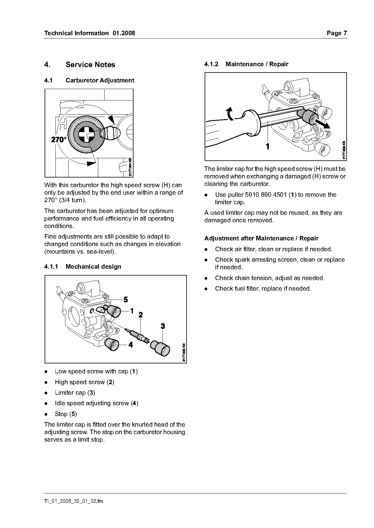
                                                         The limiter cap for the high speed screw (H) must be
                                                         removed when exchanging a damaged (H) screw or
With this carburetor the high speed screw (H) can        cleaning the carburetor.
only be adjusted by the end user within a range of       .   Use puller 5910 890 4501 (1) to remove the
270° (3/4 turn).                                             limiter cap.
The carburetor has been adjusted for optimum             A used limiter cap may not be reused, as they are
performance and fuel efficiency in all operating         damaged once removed.
conditions.
Fine adjustments are still possible to adapt to          Adjustment after Maintenance / Repair
changed conditions such as changes in elevation
(mountains vs. sea-level).                               .   Check air filter, clean or replace if needed.
                                                         .   Check spark arresting screen, clean or replace
4.1.1     Mechanical design                                  if needed.
                                                         .   Check chain tension, adjust as needed.
                                                         .   Check fuel filter, replace if needed.

.     Low speed screw with cap (1)
.     High speed screw (2)
.     Limiter cap (3)
.     Idle speed adjusting screw (4)
.     Stop (5)
The limiter cap is fitted over the knurled head of the
adjusting screw. The stop on the carburetor housing
serves as a limit stop.

TI_01_2008_30_01_02.fm
Page 8 of 13
Text of page 8 — search, copy, screen readers
Page 8                                                                      Technical Information 01.2008

4.1.3    Basic Setting without Limiter Cap               4.1.4   Securing the Limiter Cap

.   Starting from the closed position of the adjusting   A used limiter must not be reused, as they are
    screw:                                               damaged once removed.
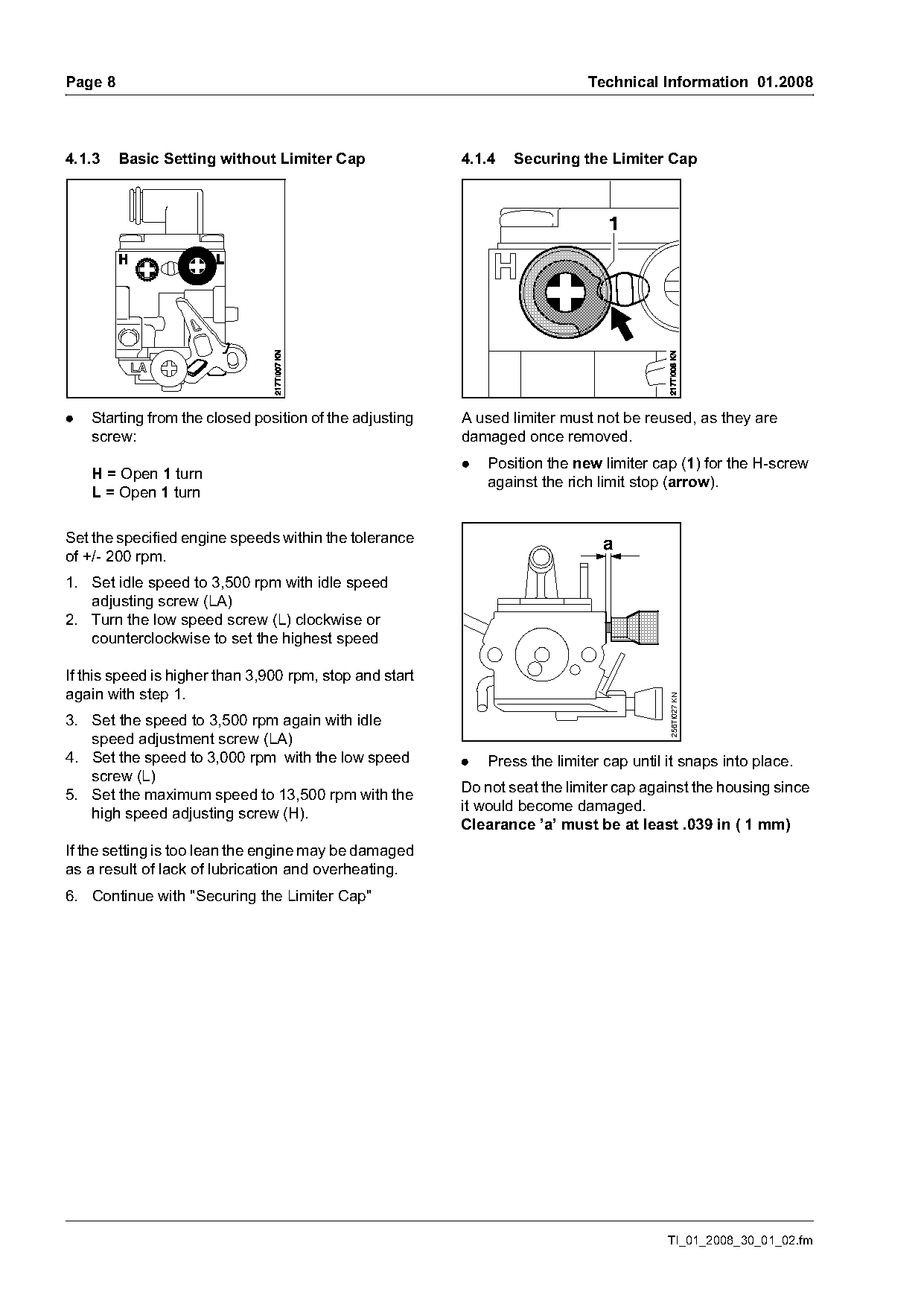
                                                         .   Position the new limiter cap (1) for the H-screw
    H = Open 1 turn
                                                             against the rich limit stop (arrow).
    L = Open 1 turn

Set the specified engine speeds within the tolerance                           a
of +/- 200 rpm.
1. Set idle speed to 3,500 rpm with idle speed
   adjusting screw (LA)
2. Turn the low speed screw (L) clockwise or
   counterclockwise to set the highest speed

If this speed is higher than 3,900 rpm, stop and start
again with step 1.
                                                                                         256TI027 KN

3. Set the speed to 3,500 rpm again with idle
   speed adjustment screw (LA)
4. Set the speed to 3,000 rpm with the low speed         .   Press the limiter cap until it snaps into place.
   screw (L)
5. Set the maximum speed to 13,500 rpm with the          Do not seat the limiter cap against the housing since
   high speed adjusting screw (H).                       it would become damaged.
                                                         Clearance ’a’ must be at least .039 in ( 1 mm)
If the setting is too lean the engine may be damaged
as a result of lack of lubrication and overheating.
6. Continue with "Securing the Limiter Cap"

                                                                                         TI_01_2008_30_01_02.fm
Page 9 of 13
Text of page 9 — search, copy, screen readers
Technical Information 01.2008                                                                                         Page 9

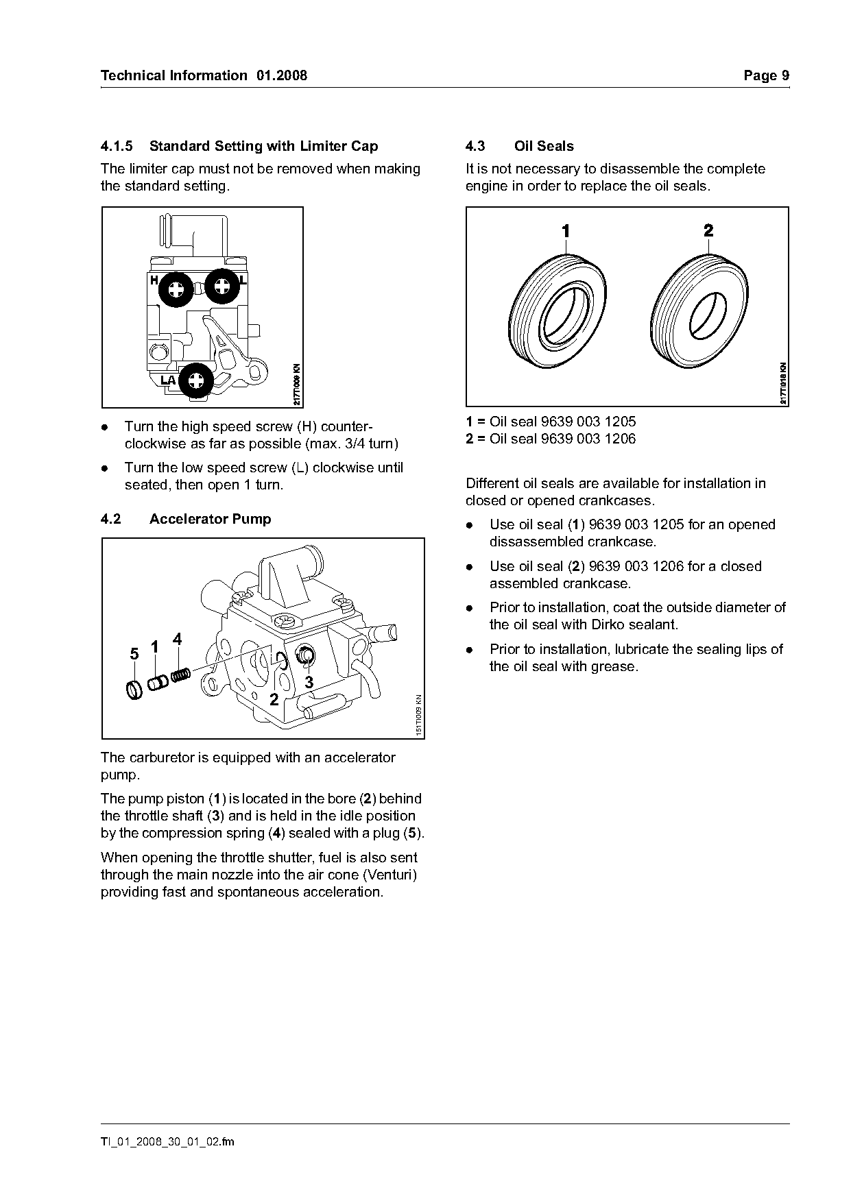
4.1.5    Standard Setting with Limiter Cap                         4.3       Oil Seals
The limiter cap must not be removed when making                    It is not necessary to disassemble the complete
the standard setting.                                              engine in order to replace the oil seals.

.     Turn the high speed screw (H) counter-                       1 = Oil seal 9639 003 1205
      clockwise as far as possible (max. 3/4 turn)                 2 = Oil seal 9639 003 1206

.     Turn the low speed screw (L) clockwise until
      seated, then open 1 turn.                                    Different oil seals are available for installation in
                                                                   closed or opened crankcases.
4.2      Accelerator Pump                                          .     Use oil seal (1) 9639 003 1205 for an opened
                                                                         dissassembled crankcase.
                                                                   .     Use oil seal (2) 9639 003 1206 for a closed
                                                                         assembled crankcase.
                                                                   .     Prior to installation, coat the outside diameter of
                                                                         the oil seal with Dirko sealant.
             4
      5 1                                                          .     Prior to installation, lubricate the sealing lips of
                                                                         the oil seal with grease.
                                  3
                             2
                                                     151TI009 KN

The carburetor is equipped with an accelerator
pump.
The pump piston (1) is located in the bore (2) behind
the throttle shaft (3) and is held in the idle position
by the compression spring (4) sealed with a plug (5).
When opening the throttle shutter, fuel is also sent
through the main nozzle into the air cone (Venturi)
providing fast and spontaneous acceleration.

TI_01_2008_30_01_02.fm
Page 10 of 13
Text of page 10 — search, copy, screen readers
Page 10                                                               Technical Information 01.2008

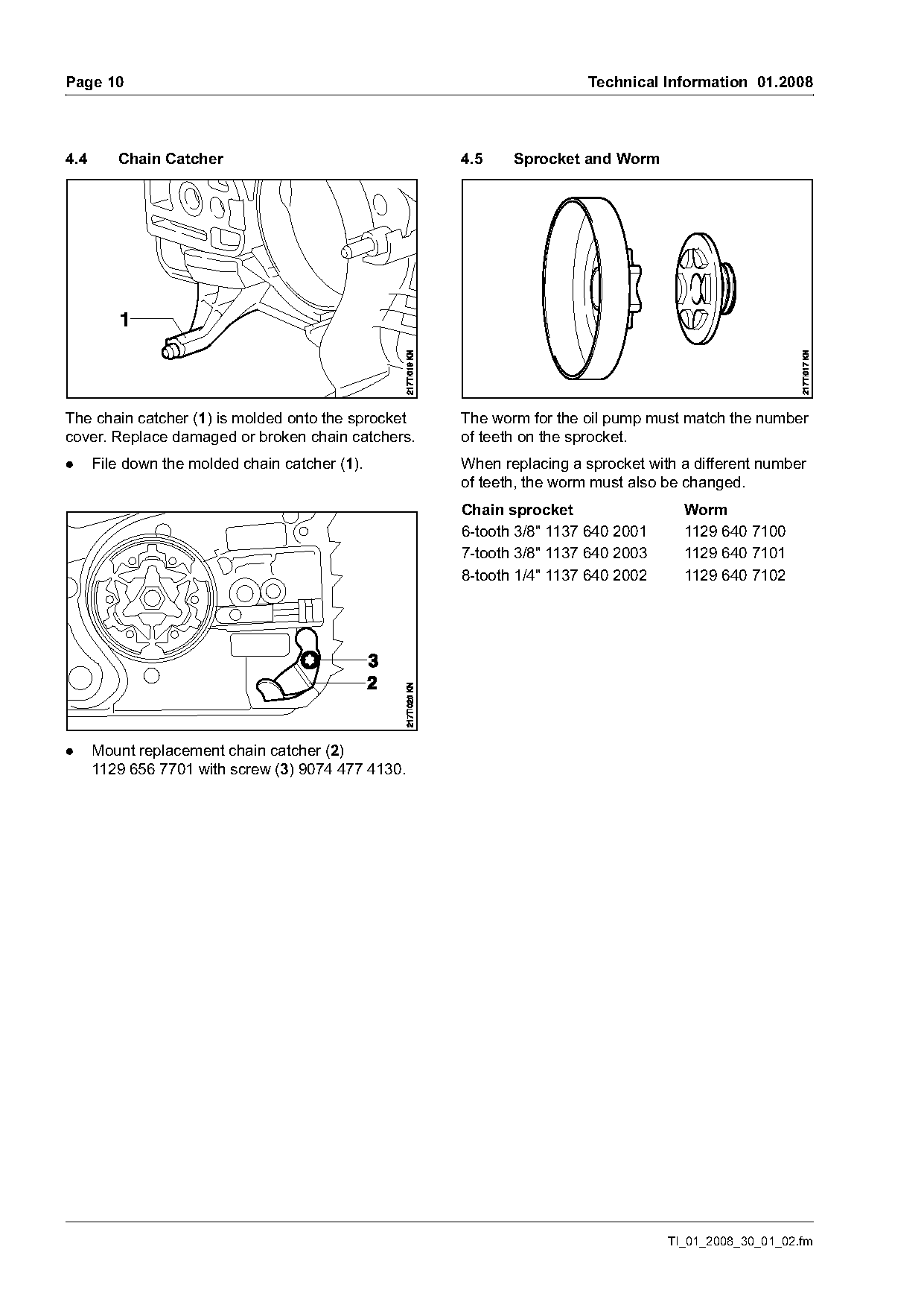
4.4      Chain Catcher                              4.5    Sprocket and Worm

The chain catcher (1) is molded onto the sprocket   The worm for the oil pump must match the number
cover. Replace damaged or broken chain catchers.    of teeth on the sprocket.
.     File down the molded chain catcher (1).       When replacing a sprocket with a different number
                                                    of teeth, the worm must also be changed.
                                                    Chain sprocket                 Worm
                                                    6-tooth 3/8" 1137 640 2001     1129 640 7100
                                                    7-tooth 3/8" 1137 640 2003     1129 640 7101
                                                    8-tooth 1/4" 1137 640 2002     1129 640 7102

.     Mount replacement chain catcher (2)
      1129 656 7701 with screw (3) 9074 477 4130.

                                                                                 TI_01_2008_30_01_02.fm
Page 11 of 13
Text of page 11 — search, copy, screen readers
Technical Information 01.2008                                                                         Page 11

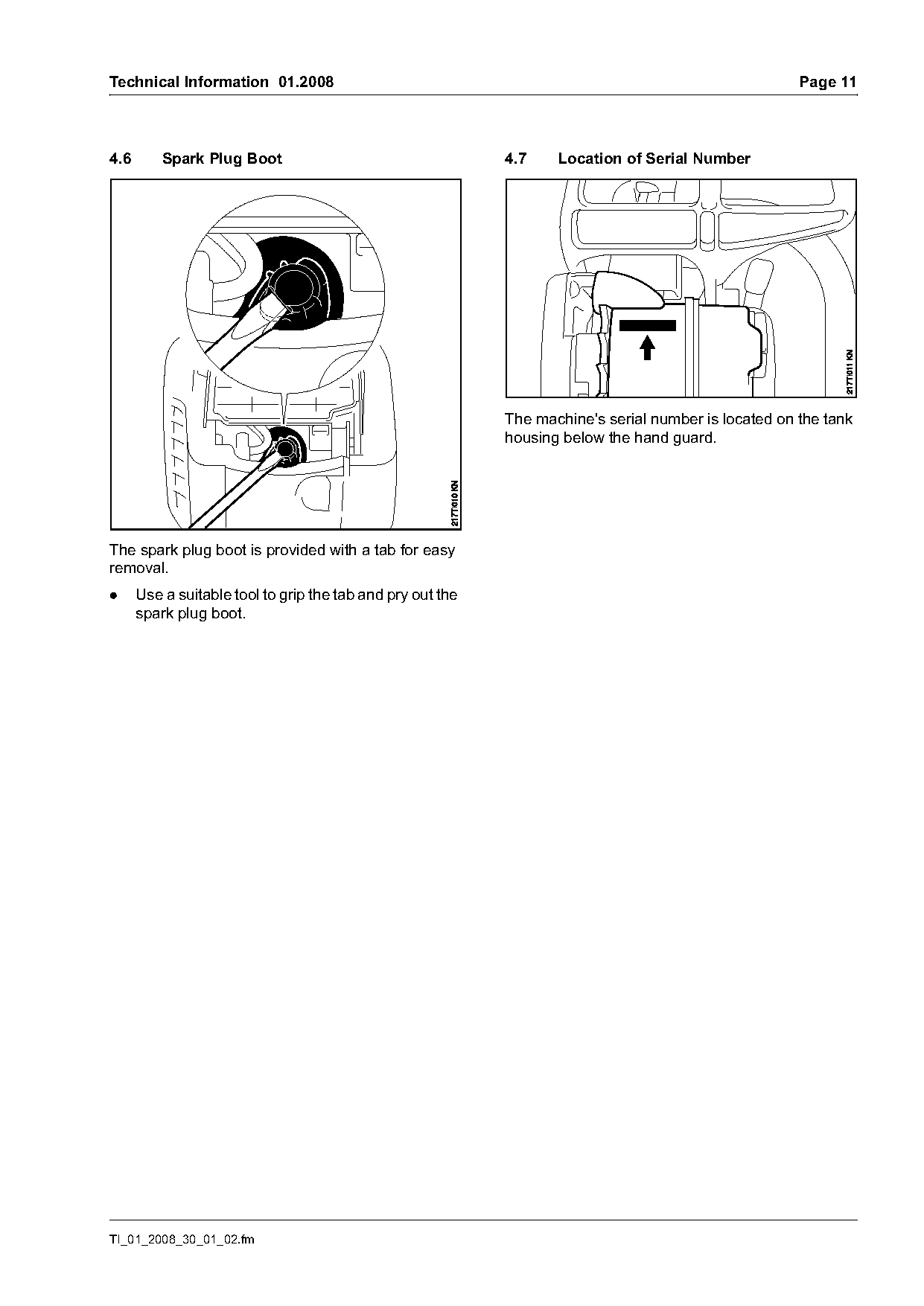
4.6       Spark Plug Boot                                   4.7    Location of Serial Number

                                                            The machine's serial number is located on the tank
                                                            housing below the hand guard.

The spark plug boot is provided with a tab for easy
removal.
.     Use a suitable tool to grip the tab and pry out the
      spark plug boot.

TI_01_2008_30_01_02.fm
Page 12 of 13
Text of page 12 — search, copy, screen readers
Page 12                                                                           Technical Information 01.2008

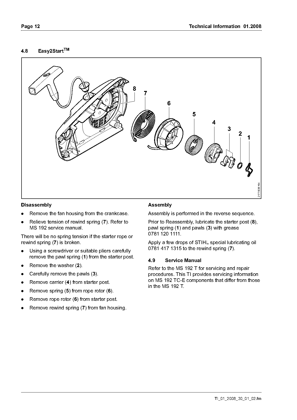
4.8      Easy2StartTM

                                                       8
                                                           7
                                                                        6
                                                                                    5
                                                                                             4
                                                                                                    3
                                                                                                         2
                                                                                                              1

                                                                                                                    217TI039 KN
Disassembly                                                    Assembly
.     Remove the fan housing from the crankcase.               Assembly is performed in the reverse sequence.
.     Relieve tension of rewind spring (7). Refer to           Prior to Reassembly, lubricate the starter post (8),
      MS 192 service manual.                                   pawl spring (1) and pawls (3) with grease
There will be no spring tension if the starter rope or         0781 120 1111.
rewind spring (7) is broken.                                   Apply a few drops of STIHL special lubricating oil
                                                               0781 417 1315 to the rewind spring (7).
.     Using a screwdriver or suitable pliers carefully
      remove the pawl spring (1) from the starter post.
                                                               4.9     Service Manual
.     Remove the washer (2).
                                                               Refer to the MS 192 T for servicing and repair
.     Carefully remove the pawls (3).                          procedures. This TI provides servicing information
.     Remove carrier (4) from starter post.                    on MS 192 TC-E components that differ from those
                                                               in the MS 192 T.
.     Remove spring (5) from rope rotor (6).
.     Remove rope rotor (6) from starter post.
.     Remove rewind spring (7) from fan housing.

                                                                                              TI_01_2008_30_01_02.fm
Page 13 of 13
Text of page 13 — search, copy, screen readers
Technical Information 01.2008                                                    Page 13

4.10    Repair Times
The repair times specified for the MS 192 T can be
used for the MS 192 TC-E.
The specified repair times assume the work is
performed by trained personnel in a properly
equipped workshop.

5.      Spare Parts
A separate spare parts list is available for the new
machine.
The new machine is included in the STIHL Service
Communication System                 from
issue 01/2008.

© ANDREAS STIHL AG & Co. KG, 2008                      Technical Documentation
                                                       D1/MTK-ni

TI_01_2008_30_01_02.fm
Most of these PDFs embed fonts with a shifted character map, so the text above was recovered rather than copied — read it as a faithful but imperfect transcription, and treat the page image above each block as the authority where the two disagree — the figures exist only there, because they are vector drawings that text extraction cannot keep.