Technical Information · issue 13 of 2008
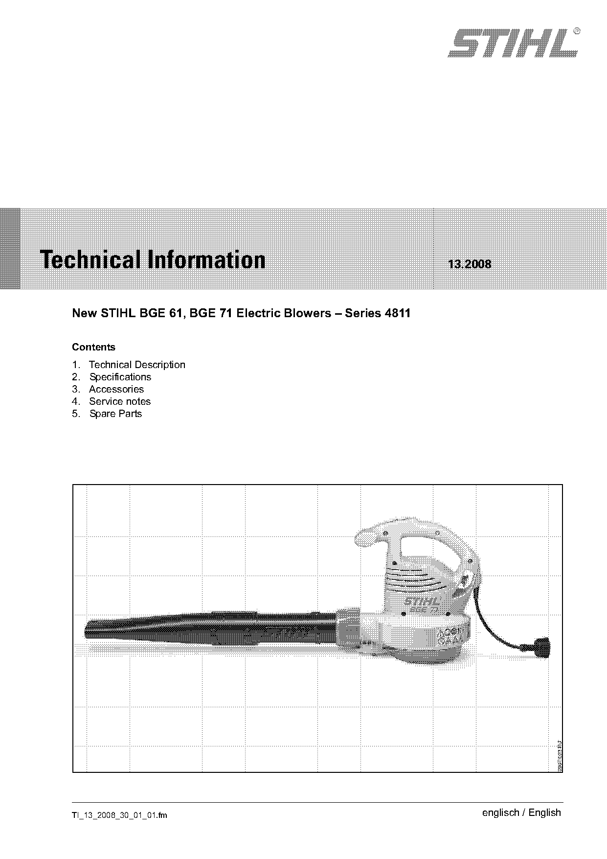
New STIHL BGE 61, BGE 71 Electric Blowers
IssueTI 13/2008
Full text
Page 1 of 8
Text of page 1 — search, copy, screen readers
STIH)

Technical Information                                       13.2008

  New STIHL BGE 61, BGE 71 Electric Blowers – Series 4811

  Contents
  1.   Technical Description
  2.   Specifications
  3.   Accessories
  4.   Service notes
  5.   Spare Parts

  TI_13_2008_30_01_01.fm                                         englisch / English
Page 2 of 8
Text of page 2 — search, copy, screen readers
Page 2                                                                                     Technical Information 13.2008

The new hand-held BGE 61, BGE 71 electric
blowers are suitable for home use applications such
as blowing leaves, light debris, parking areas and
                                                                                     3
driveways.
                                                                                     5
Equipped with (special accessory) vacuum                                             4
attachment 4811 700 2200, the BGE 71 is also
suitable for picking up dry leaves and other
lightweight, loose yard debris.

                                                                                                                                290TI002 KN
1.       Technical Description

1.1      General features
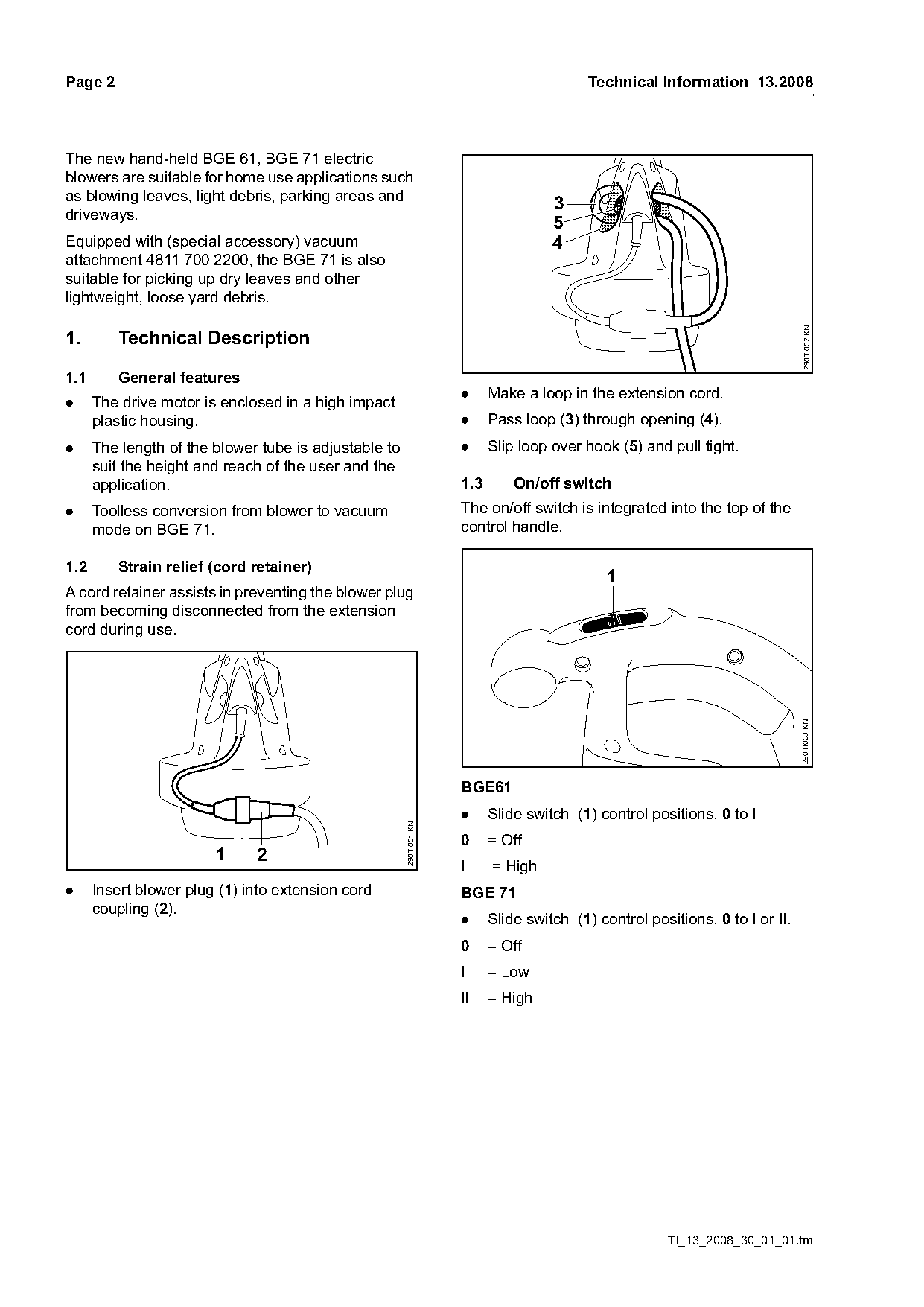
                                                                     .     Make a loop in the extension cord.
.     The drive motor is enclosed in a high impact
      plastic housing.                                               .     Pass loop (3) through opening (4).
.     The length of the blower tube is adjustable to                 .     Slip loop over hook (5) and pull tight.
      suit the height and reach of the user and the
      application.                                                   1.3       On/off switch
.     Toolless conversion from blower to vacuum                      The on/off switch is integrated into the top of the
      mode on BGE 71.                                                control handle.

1.2      Strain relief (cord retainer)
                                                                                              1
A cord retainer assists in preventing the blower plug
from becoming disconnected from the extension
cord during use.

                                                                                                                               290TI003 KN
                                                                     BGE61
                                                                     .     Slide switch (1) control positions, 0 to I
                                                       290TI001 KN

                                                                     0     = Off
                        1     2
                                                                     I     = High
.     Insert blower plug (1) into extension cord                     BGE 71
      coupling (2).
                                                                     .     Slide switch (1) control positions, 0 to I or II.
                                                                     0     = Off
                                                                     I     = Low
                                                                     II    = High

                                                                                                       TI_13_2008_30_01_01.fm
Page 3 of 8
Text of page 3 — search, copy, screen readers
Technical Information 13.2008                                                                                        Page 3

1.4     Interlock switch on BGE 71                                 2.       Specifications

                                                                   2.1      Motor (BGE 61, 71)
                                                                   Power supply      120 V, 60 Hz, 9.2 A
                                                                   Fuse              15 A
                                                                   Rating            1100 W
                                                                   Insulation        Double insulation

                                                                   2.2      Maximum air flow rate
                                                                                     Blower mode        Vacuum mode

                                                     290TI005 KN
                                                                   BGE 61            394 cf/min
                                                                                     (670 m3/h)         ---
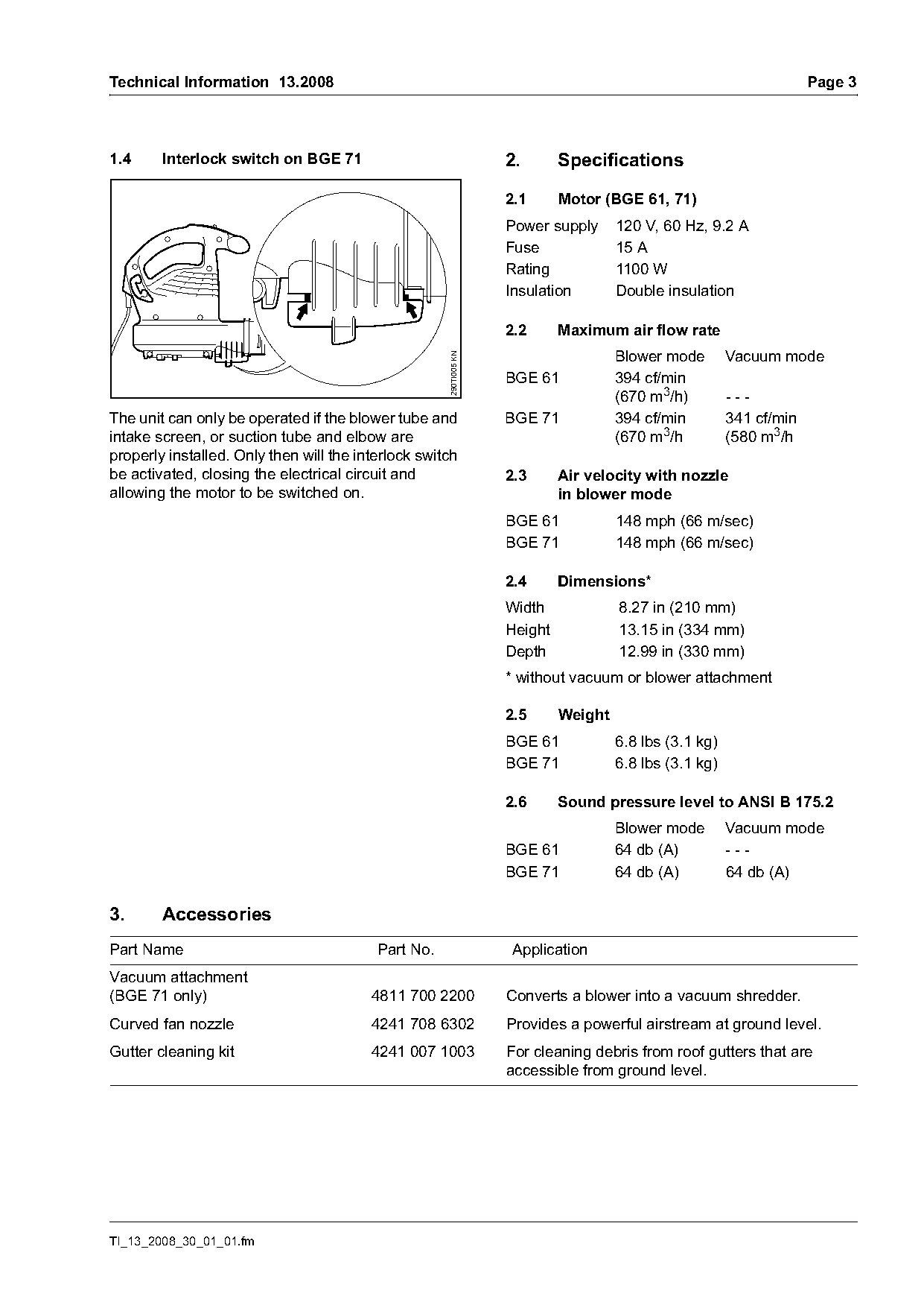
The unit can only be operated if the blower tube and               BGE 71            394 cf/min         341 cf/min
intake screen, or suction tube and elbow are                                         (670 m3/h          (580 m3/h
properly installed. Only then will the interlock switch
be activated, closing the electrical circuit and                   2.3      Air velocity with nozzle
allowing the motor to be switched on.                                       in blower mode
                                                                   BGE 61            148 mph (66 m/sec)
                                                                   BGE 71            148 mph (66 m/sec)

                                                                   2.4      Dimensions*
                                                                   Width             8.27 in (210 mm)
                                                                   Height            13.15 in (334 mm)
                                                                   Depth             12.99 in (330 mm)
                                                                   * without vacuum or blower attachment

                                                                   2.5      Weight
                                                                   BGE 61            6.8 lbs (3.1 kg)
                                                                   BGE 71            6.8 lbs (3.1 kg)

                                                                   2.6      Sound pressure level to ANSI B 175.2
                                                                                     Blower mode        Vacuum mode
                                                                   BGE 61            64 db (A)          ---
                                                                   BGE 71            64 db (A)          64 db (A)

3.      Accessories
Part Name                                 Part No.                  Application
Vacuum attachment
(BGE 71 only)                            4811 700 2200             Converts a blower into a vacuum shredder.
Curved fan nozzle                        4241 708 6302             Provides a powerful airstream at ground level.
Gutter cleaning kit                      4241 007 1003             For cleaning debris from roof gutters that are
                                                                   accessible from ground level.

TI_13_2008_30_01_01.fm
Page 4 of 8
Text of page 4 — search, copy, screen readers
Page 4                                                                                  Technical Information 13.2008

4.        Service notes                                            4.2       BGE 61

Repairs may only be performed by a qualified                                   1
technician observing all safety precautions found in
the product instruction manual.
Always disconnect the power cord from the power
supply before carrying out repairs.
Proper testing procedures for electric products must
be followed after all repairs.

4.1       Removal and installation of blower
          housing                                                              2                                3

                                                                                                                          290TI007 KN
                                                                   4.2.1     On/off switch
                                                     290TI006 KN

                                                                   .     Remove housing (see 4.1.1).
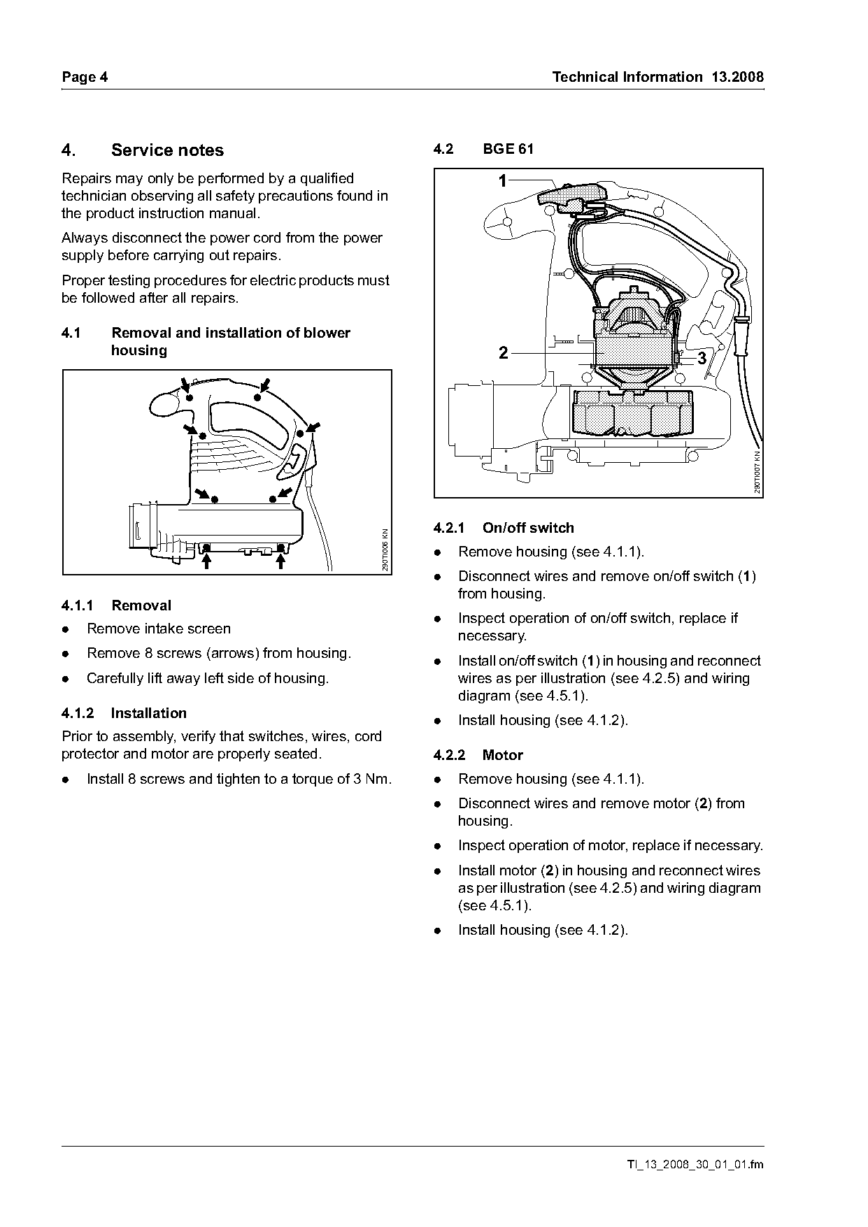
                                                                   .     Disconnect wires and remove on/off switch (1)
                                                                         from housing.
4.1.1     Removal
                                                                   .     Inspect operation of on/off switch, replace if
.     Remove intake screen
                                                                         necessary.
.     Remove 8 screws (arrows) from housing.
                                                                   .     Install on/off switch (1) in housing and reconnect
.     Carefully lift away left side of housing.                          wires as per illustration (see 4.2.5) and wiring
                                                                         diagram (see 4.5.1).
4.1.2     Installation
                                                                   .     Install housing (see 4.1.2).
Prior to assembly, verify that switches, wires, cord
protector and motor are properly seated.                           4.2.2     Motor
.     Install 8 screws and tighten to a torque of 3 Nm.            .     Remove housing (see 4.1.1).
                                                                   .     Disconnect wires and remove motor (2) from
                                                                         housing.
                                                                   .     Inspect operation of motor, replace if necessary.
                                                                   .     Install motor (2) in housing and reconnect wires
                                                                         as per illustration (see 4.2.5) and wiring diagram
                                                                         (see 4.5.1).
                                                                   .     Install housing (see 4.1.2).

                                                                                                    TI_13_2008_30_01_01.fm
Page 5 of 8
Text of page 5 — search, copy, screen readers
Technical Information 13.2008                                                                                    Page 5

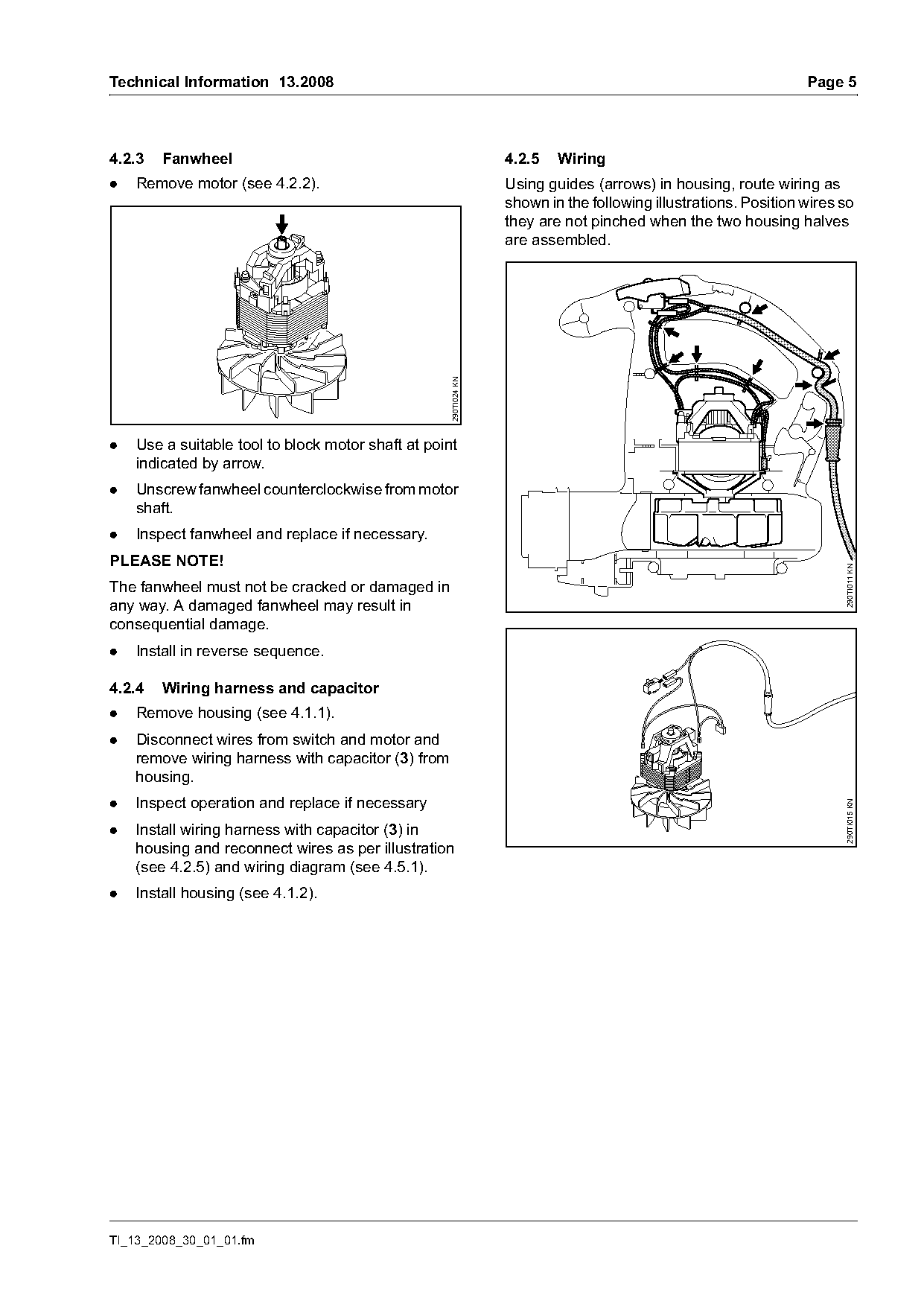
4.2.3   Fanwheel                                                  4.2.5   Wiring
.   Remove motor (see 4.2.2).                                     Using guides (arrows) in housing, route wiring as
                                                                  shown in the following illustrations. Position wires so
                                                                  they are not pinched when the two housing halves
                                                                  are assembled.

                                                    290TI024 KN
.   Use a suitable tool to block motor shaft at point
    indicated by arrow.
.   Unscrew fanwheel counterclockwise from motor
    shaft.
.   Inspect fanwheel and replace if necessary.
PLEASE NOTE!

                                                                                                                       290TI011 KN
The fanwheel must not be cracked or damaged in
any way. A damaged fanwheel may result in
consequential damage.
.   Install in reverse sequence.

4.2.4   Wiring harness and capacitor
.   Remove housing (see 4.1.1).
.   Disconnect wires from switch and motor and
    remove wiring harness with capacitor (3) from
    housing.
.   Inspect operation and replace if necessary

                                                                                                                       290TI015 KN
.   Install wiring harness with capacitor (3) in
    housing and reconnect wires as per illustration
    (see 4.2.5) and wiring diagram (see 4.5.1).
.   Install housing (see 4.1.2).

TI_13_2008_30_01_01.fm
Page 6 of 8
Text of page 6 — search, copy, screen readers
Page 6                                                                                  Technical Information 13.2008

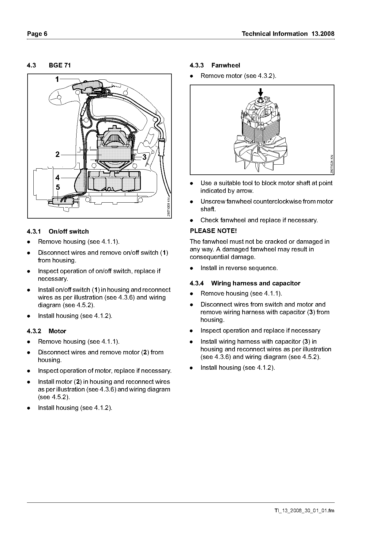
4.3       BGE 71                                                     4.3.3   Fanwheel
                                                                     .   Remove motor (see 4.3.2).
            1

            2                                3

                                                                                                                         290TI024 KN
            4
                                                                     .   Use a suitable tool to block motor shaft at point
            5                                                            indicated by arrow.
                                                       290TI009 KN

                                                                     .   Unscrew fanwheel counterclockwise from motor
                                                                         shaft.
                                                                     .   Check fanwheel and replace if necessary.
4.3.1     On/off switch                                              PLEASE NOTE!
.     Remove housing (see 4.1.1).                                    The fanwheel must not be cracked or damaged in
                                                                     any way. A damaged fanwheel may result in
.     Disconnect wires and remove on/off switch (1)
                                                                     consequential damage.
      from housing.
                                                                     .   Install in reverse sequence.
.     Inspect operation of on/off switch, replace if
      necessary.
                                                                     4.3.4   Wiring harness and capacitor
.     Install on/off switch (1) in housing and reconnect
                                                                     .   Remove housing (see 4.1.1).
      wires as per illustration (see 4.3.6) and wiring
      diagram (see 4.5.2).                                           .   Disconnect wires from switch and motor and
                                                                         remove wiring harness with capacitor (3) from
.     Install housing (see 4.1.2).
                                                                         housing.
4.3.2     Motor                                                      .   Inspect operation and replace if necessary
.     Remove housing (see 4.1.1).                                    .   Install wiring harness with capacitor (3) in
                                                                         housing and reconnect wires as per illustration
.     Disconnect wires and remove motor (2) from
                                                                         (see 4.3.6) and wiring diagram (see 4.5.2).
      housing.
                                                                     .   Install housing (see 4.1.2).
.     Inspect operation of motor, replace if necessary.
.     Install motor (2) in housing and reconnect wires
      as per illustration (see 4.3.6) and wiring diagram
      (see 4.5.2).
.     Install housing (see 4.1.2).

                                                                                                    TI_13_2008_30_01_01.fm
Page 7 of 8
Text of page 7 — search, copy, screen readers
Technical Information 13.2008                                                                                         Page 7

4.3.5   Interlock switch                                              4.4       Overload Circuit Breaker
.   Remove housing (see 4.1.1).                                       The overload circuit breaker interrupts the power
                                                                      supply to the machine in the event of a mechanical
.   Remove air baffle (4).
                                                                      overload.
.   Disconnect wires and remove interlock
                                                                      If the overload circuit breaker has tripped,
    switch (5) from housing.
                                                                      switch the unit to the off position and
.   Inspect operation of interlock switch, replace if                 disconnect the power supply:
    necessary.
                                                                      .     Verify the cause of the mechanical overload
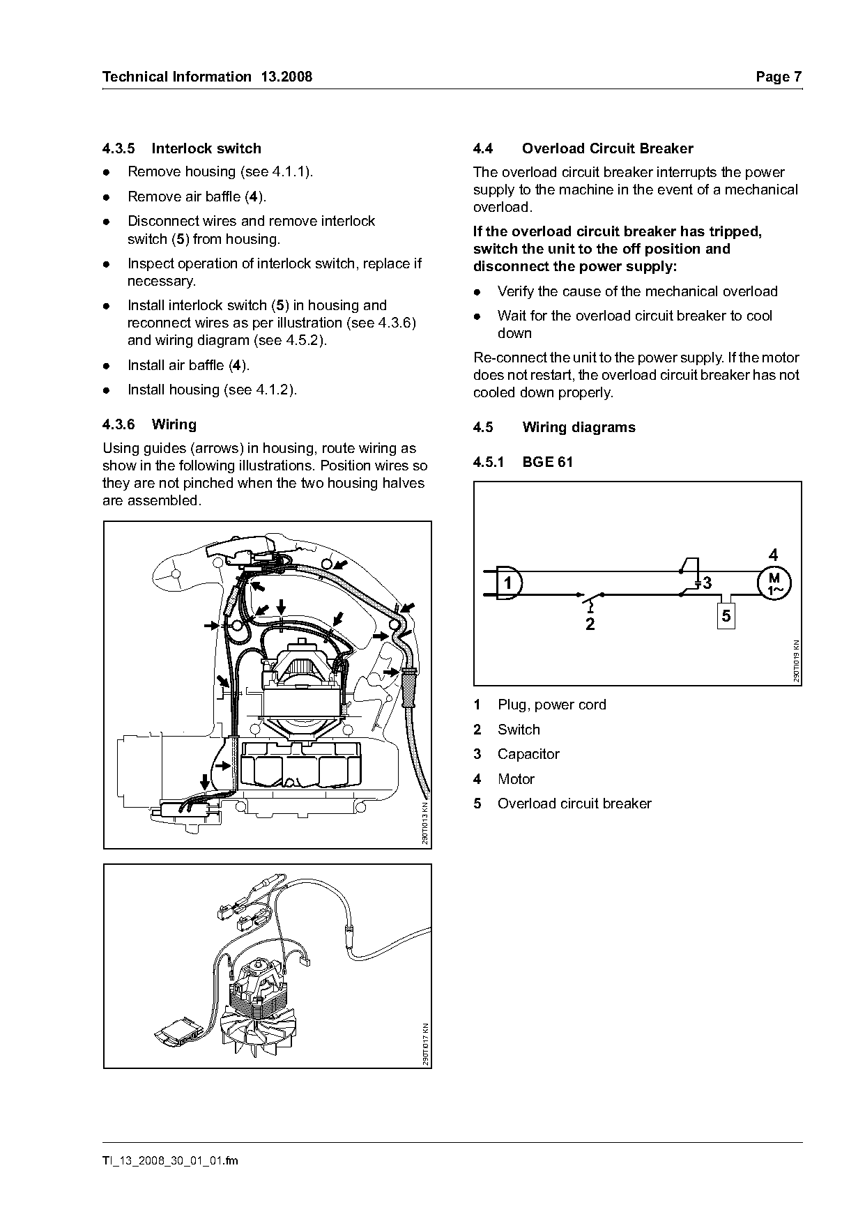
.   Install interlock switch (5) in housing and
                                                                      .     Wait for the overload circuit breaker to cool
    reconnect wires as per illustration (see 4.3.6)
                                                                            down
    and wiring diagram (see 4.5.2).
                                                                      Re-connect the unit to the power supply. If the motor
.   Install air baffle (4).
                                                                      does not restart, the overload circuit breaker has not
.   Install housing (see 4.1.2).                                      cooled down properly.

4.3.6   Wiring                                                        4.5       Wiring diagrams
Using guides (arrows) in housing, route wiring as
show in the following illustrations. Position wires so                4.5.1     BGE 61
they are not pinched when the two housing halves
are assembled.

                                                                                                                        4
                                                                            1                                3

                                                                                          2                      5

                                                                                                                            290TI019 KN
                                                                      1     Plug, power cord
                                                                      2     Switch
                                                                      3     Capacitor
                                                                      4     Motor
                                                                      5     Overload circuit breaker
                                                      290TI013 KN
                                                        290TI017 KN

TI_13_2008_30_01_01.fm
Page 8 of 8
Text of page 8 — search, copy, screen readers
Page 8                                                                       Technical Information 13.2008

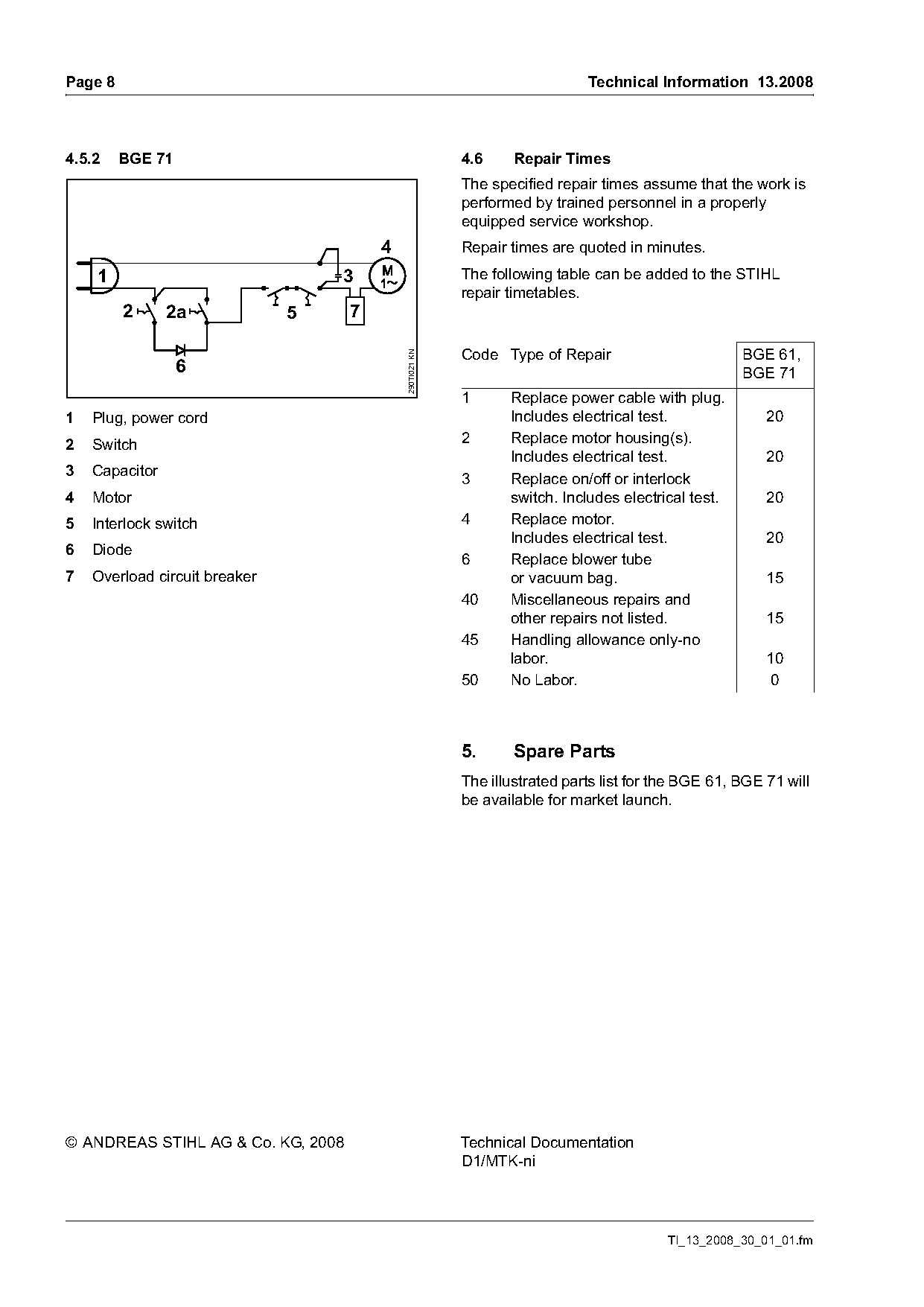
4.5.2    BGE 71                                           4.6     Repair Times
                                                          The specified repair times assume that the work is
                                                          performed by trained personnel in a properly
                                                          equipped service workshop.
                                        4                 Repair times are quoted in minutes.
    1                              3                      The following table can be added to the STIHL
                                                          repair timetables.
         2      2a             5    7

                                                          Code Type of Repair                        BGE 61,

                                            290TI021 KN
                  6                                                                                  BGE 71
                                                          1      Replace power cable with plug.
1   Plug, power cord                                             Includes electrical test.               20
2   Switch                                                2      Replace motor housing(s).
                                                                 Includes electrical test.               20
3   Capacitor
                                                          3      Replace on/off or interlock
4   Motor                                                        switch. Includes electrical test.       20
5   Interlock switch                                      4      Replace motor.
                                                                 Includes electrical test.               20
6   Diode
                                                          6      Replace blower tube
7   Overload circuit breaker                                     or vacuum bag.                          15
                                                          40     Miscellaneous repairs and
                                                                 other repairs not listed.               15
                                                          45     Handling allowance only-no
                                                                 labor.                                  10
                                                          50     No Labor.                                0

                                                          5.      Spare Parts
                                                          The illustrated parts list for the BGE 61, BGE 71 will
                                                          be available for market launch.

© ANDREAS STIHL AG & Co. KG, 2008                         Technical Documentation
                                                          D1/MTK-ni

                                                                                         TI_13_2008_30_01_01.fm
Most of these PDFs embed fonts with a shifted character map, so the text above was recovered rather than copied — read it as a faithful but imperfect transcription, and treat the page image above each block as the authority where the two disagree — the figures exist only there, because they are vector drawings that text extraction cannot keep.