Technical Information · issue 39 of 2008
New Edger STIHL FC 56
IssueTI 39/2008
Full text
Page 1 of 15
Text of page 1 — search, copy, screen readers
STIH)

Technical Information                                   39.2008

  New Edger STIHL FC 56 – Series 4144

  Contents
  1.   Technical description
  2.   Specifications
  3.   Blade
  4.   Instructions for the user
  5.   Special accessories
  6.   Servicing accessories
  7.   Spare parts
  8.   Servicing

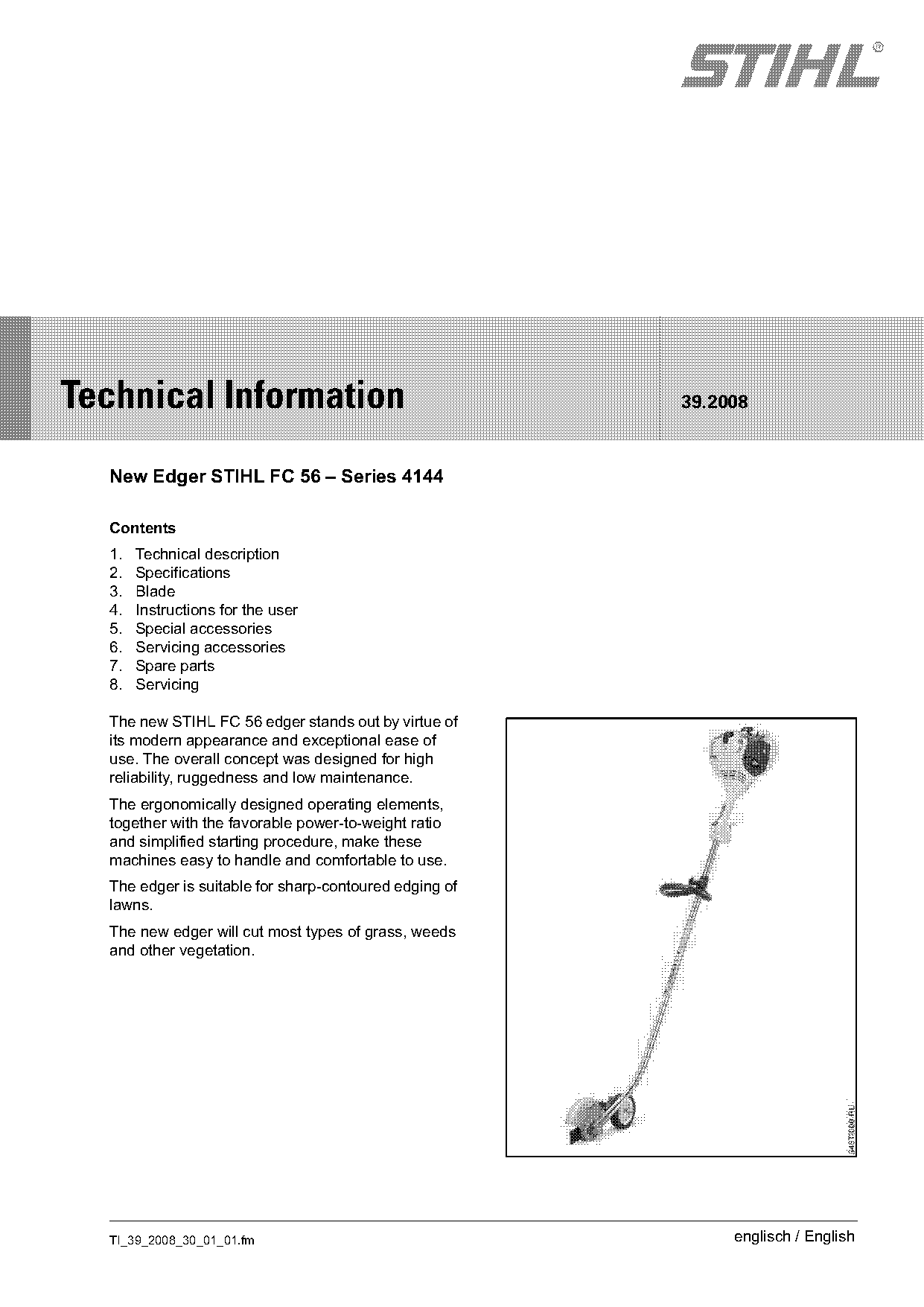
  The new STIHL FC 56 edger stands out by virtue of
  its modern appearance and exceptional ease of
  use. The overall concept was designed for high
  reliability, ruggedness and low maintenance.
  The ergonomically designed operating elements,
  together with the favorable power-to-weight ratio
  and simplified starting procedure, make these
  machines easy to handle and comfortable to use.
  The edger is suitable for sharp-contoured edging of
  lawns.
  The new edger will cut most types of grass, weeds
  and other vegetation.

  TI_39_2008_30_01_01.fm                                     englisch / English
Page 2 of 15
Text of page 2 — search, copy, screen readers
Page 2                                                                                Technical Information 39.2008

1.       Technical description                                    1.3     Engine with stratified scavenging

1.1      Function of stop switch and ignition                     1.3.1   Mechanical Design


                                                    546TI000 KN

                                                                    3
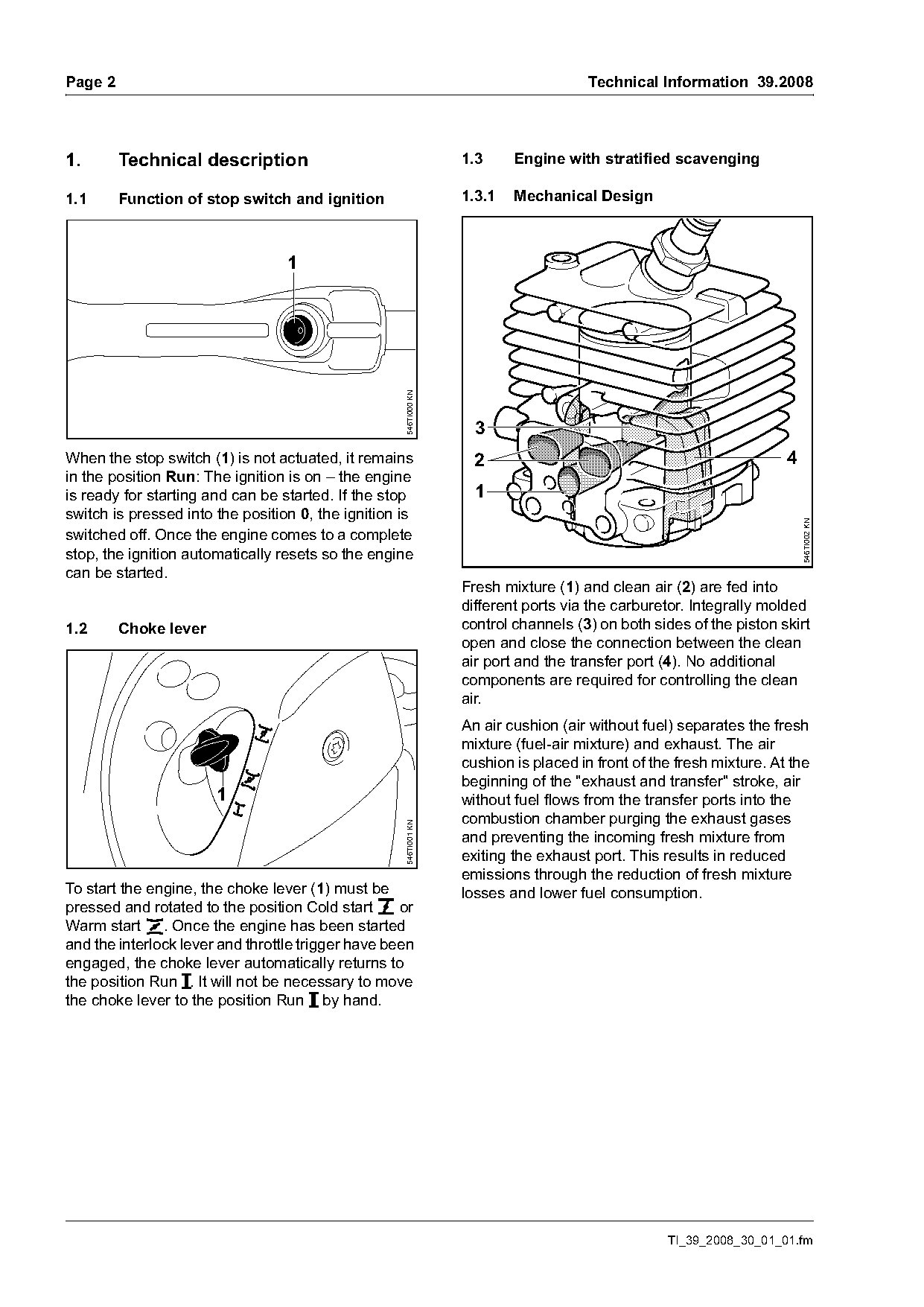
When the stop switch (1) is not actuated, it remains                2                                                4
in the position Run: The ignition is on – the engine
is ready for starting and can be started. If the stop               1
switch is pressed into the position 0, the ignition is

                                                                                                                         546TI002 KN
switched off. Once the engine comes to a complete
stop, the ignition automatically resets so the engine
can be started.
                                                                  Fresh mixture (1) and clean air (2) are fed into
                                                                  different ports via the carburetor. Integrally molded
1.2      Choke lever                                              control channels (3) on both sides of the piston skirt
                                                                  open and close the connection between the clean
                                                                  air port and the transfer port (4). No additional
                                                                  components are required for controlling the clean
                                                                  air.
                                                                  An air cushion (air without fuel) separates the fresh
                                                                  mixture (fuel-air mixture) and exhaust. The air
                                                                  cushion is placed in front of the fresh mixture. At the
                                                                  beginning of the "exhaust and transfer" stroke, air
                       1                                          without fuel flows from the transfer ports into the
                                                                  combustion chamber purging the exhaust gases
                                                    546TI001 KN

                                                                  and preventing the incoming fresh mixture from
                                                                  exiting the exhaust port. This results in reduced
                                                                  emissions through the reduction of fresh mixture
To start the engine, the choke lever (1) must be                  losses and lower fuel consumption.
pressed and rotated to the position Cold start g or
Warm start <. Once the engine has been started
and the interlock lever and throttle trigger have been
engaged, the choke lever automatically returns to
the position Run F. It will not be necessary to move
the choke lever to the position Run F by hand.

                                                                                                  TI_39_2008_30_01_01.fm
Page 3 of 15
Text of page 3 — search, copy, screen readers
Technical Information 39.2008                                                                                 Page 3

1.3.2     Carburetor


  2                  3

                                                      2 6 3           5


                                                                                                                    546TI003 KN
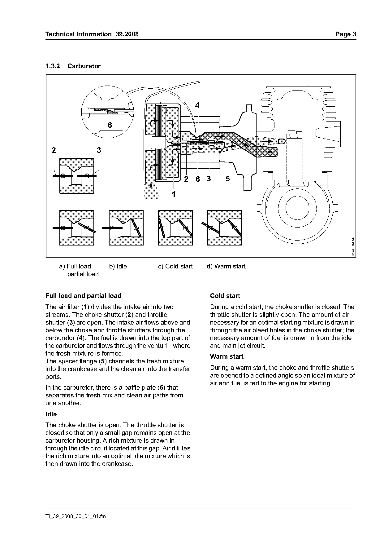
       a) Full load,     b) Idle            c) Cold start       d) Warm start
          partial load

Full load and partial load                                       Cold start
The air filter (1) divides the intake air into two               During a cold start, the choke shutter is closed. The
streams. The choke shutter (2) and throttle                      throttle shutter is slightly open. The amount of air
shutter (3) are open. The intake air flows above and             necessary for an optimal starting mixture is drawn in
below the choke and throttle shutters through the                through the air bleed holes in the choke shutter; the
carburetor (4). The fuel is drawn into the top part of           necessary amount of fuel is drawn in from the idle
the carburetor and flows through the venturi – where             and main jet circuit.
the fresh mixture is formed.                                     Warm start
The spacer flange (5) channels the fresh mixture
into the crankcase and the clean air into the transfer           During a warm start, the choke and throttle shutters
ports.                                                           are opened to a defined angle so an ideal mixture of
                                                                 air and fuel is fed to the engine for starting.
In the carburetor, there is a baffle plate (6) that
separates the fresh mix and clean air paths from
one another.
Idle
The choke shutter is open. The throttle shutter is
closed so that only a small gap remains open at the
carburetor housing. A rich mixture is drawn in
through the idle circuit located at this gap. Air dilutes
the rich mixture into an optimal idle mixture which is
then drawn into the crankcase.

TI_39_2008_30_01_01.fm
Page 4 of 15
Text of page 4 — search, copy, screen readers
Page 4                                                                            Technical Information 39.2008

1.4      Loop handle
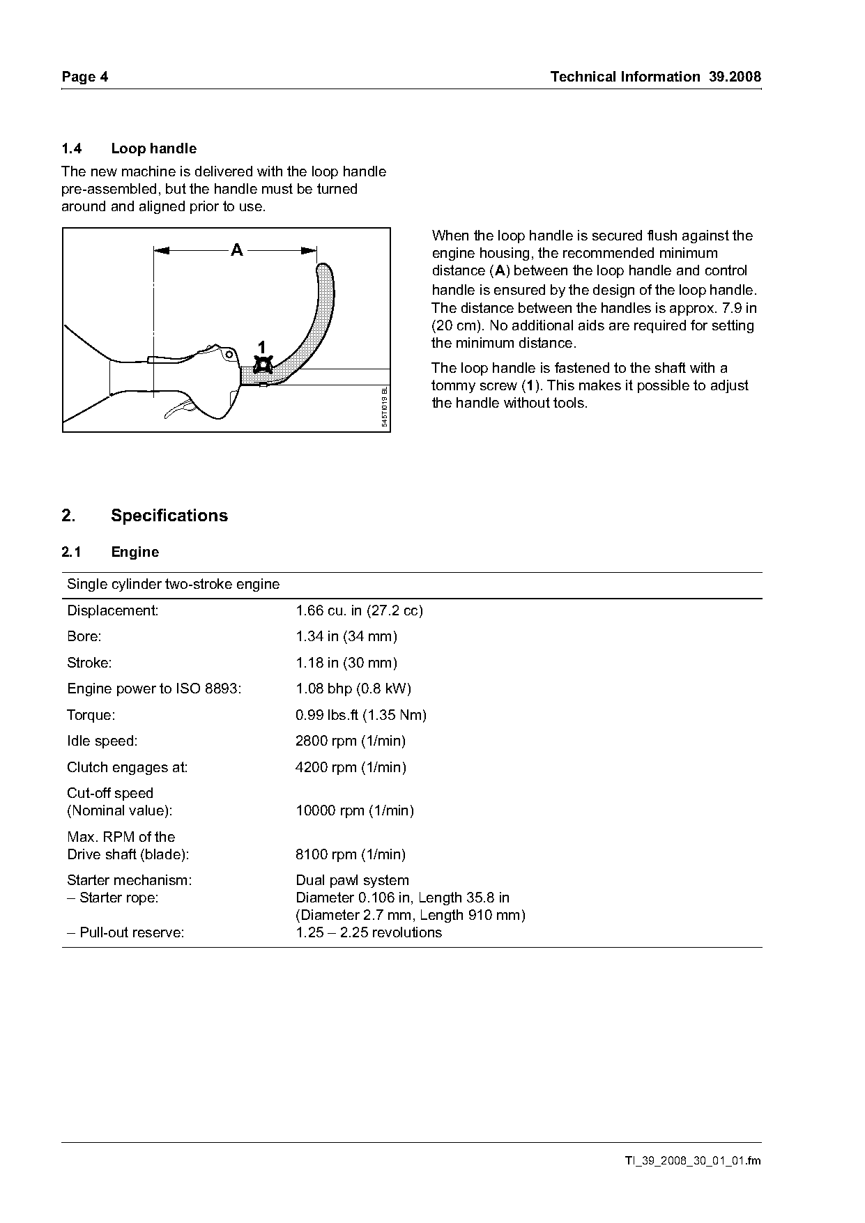
The new machine is delivered with the loop handle
pre-assembled, but the handle must be turned
around and aligned prior to use.

                                                               When the loop handle is secured flush against the
                          A                                    engine housing, the recommended minimum
                                                               distance (A) between the loop handle and control
                                                               handle is ensured by the design of the loop handle.
                                                               The distance between the handles is approx. 7.9 in
                                                               (20 cm). No additional aids are required for setting
                              1                                the minimum distance.
                                                               The loop handle is fastened to the shaft with a
                                                 545TI019 BL   tommy screw (1). This makes it possible to adjust
                                                               the handle without tools.

2.       Specifications

2.1      Engine

Single cylinder two-stroke engine
Displacement:                       1.66 cu. in (27.2 cc)
Bore:                               1.34 in (34 mm)
Stroke:                             1.18 in (30 mm)
Engine power to ISO 8893:           1.08 bhp (0.8 kW)
Torque:                             0.99 lbs.ft (1.35 Nm)
Idle speed:                         2800 rpm (1/min)
Clutch engages at:                  4200 rpm (1/min)
Cut-off speed
(Nominal value):                    10000 rpm (1/min)
Max. RPM of the
Drive shaft (blade):                8100 rpm (1/min)
Starter mechanism:                  Dual pawl system
– Starter rope:                     Diameter 0.106 in, Length 35.8 in
                                    (Diameter 2.7 mm, Length 910 mm)
– Pull-out reserve:                 1.25 – 2.25 revolutions

                                                                                             TI_39_2008_30_01_01.fm
Page 5 of 15
Text of page 5 — search, copy, screen readers
Technical Information 39.2008                                                                     Page 5

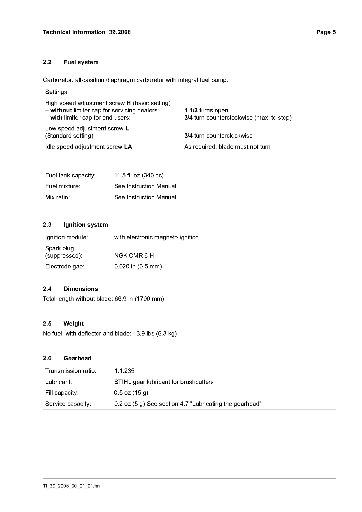
2.2     Fuel system

Carburetor: all-position diaphragm carburetor with integral fuel pump.

Settings
High speed adjustment screw H (basic setting)
– without limiter cap for servicing dealers:           1 1/2 turns open
– with limiter cap for end users:                      3/4 turn counterclockwise (max. to stop)
Low speed adjustment screw L
(Standard setting):                                    3/4 turn counterclockwise
Idle speed adjustment screw LA:                        As required, blade must not turn

Fuel tank capacity:        11.5 fl. oz (340 cc)
Fuel mixture:              See Instruction Manual
Mix ratio:                 See Instruction Manual

2.3     Ignition system

Ignition module:           with electronic magneto ignition
Spark plug
(suppressed):              NGK CMR 6 H
Electrode gap:             0.020 in (0.5 mm)

2.4     Dimensions
Total length without blade: 66.9 in (1700 mm)

2.5     Weight
No fuel, with deflector and blade: 13.9 lbs (6.3 kg)

2.6     Gearhead

Transmission ratio:        1:1.235
Lubricant:                 STIHL gear lubricant for brushcutters
Fill capacity:             0.5 oz (15 g)
Service capacity:          0.2 oz (5 g) See section 4.7 "Lubricating the gearhead"

TI_39_2008_30_01_01.fm
Page 6 of 15
Text of page 6 — search, copy, screen readers
Page 6                                                                                  Technical Information 39.2008

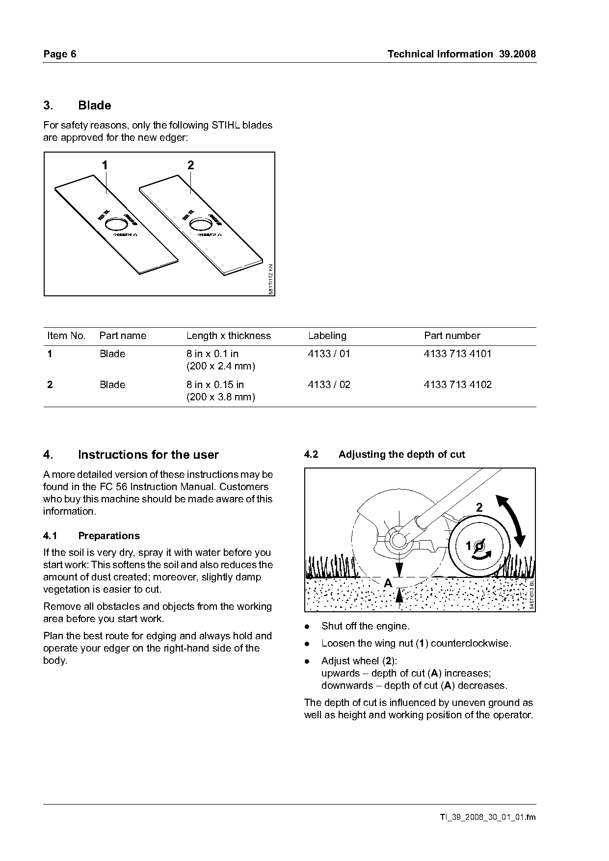
3.       Blade
For safety reasons, only the following STIHL blades
are approved for the new edger:

              1                   2


                                                     681TI172 KN

Item No.     Part name            Length x thickness               Labeling                     Part number
1            Blade                8 in x 0.1 in                    4133 / 01                    4133 713 4101
                                  (200 x 2.4 mm)
2            Blade                8 in x 0.15 in                   4133 / 02                    4133 713 4102
                                  (200 x 3.8 mm)

4.       Instructions for the user                                 4.2      Adjusting the depth of cut

A more detailed version of these instructions may be
found in the FC 56 Instruction Manual. Customers
who buy this machine should be made aware of this
information.                                                                                                2

4.1      Preparations
If the soil is very dry, spray it with water before you
                                                                                                        1
start work: This softens the soil and also reduces the
amount of dust created; moreover, slightly damp
                                                                                       A
                                                                                                                       545TI013 BL

vegetation is easier to cut.
Remove all obstacles and objects from the working
area before you start work.
                                                                   .     Shut off the engine.
Plan the best route for edging and always hold and
operate your edger on the right-hand side of the                   .     Loosen the wing nut (1) counterclockwise.
body.                                                              .     Adjust wheel (2):
                                                                         upwards – depth of cut (A) increases;
                                                                         downwards – depth of cut (A) decreases.
                                                                   The depth of cut is influenced by uneven ground as
                                                                   well as height and working position of the operator.

                                                                                                   TI_39_2008_30_01_01.fm
Page 7 of 15
Text of page 7 — search, copy, screen readers
Technical Information 39.2008                                                                                    Page 7


                             3
                         B
                                                  545TI014 BL

                                                                                                                       545TI016 BL
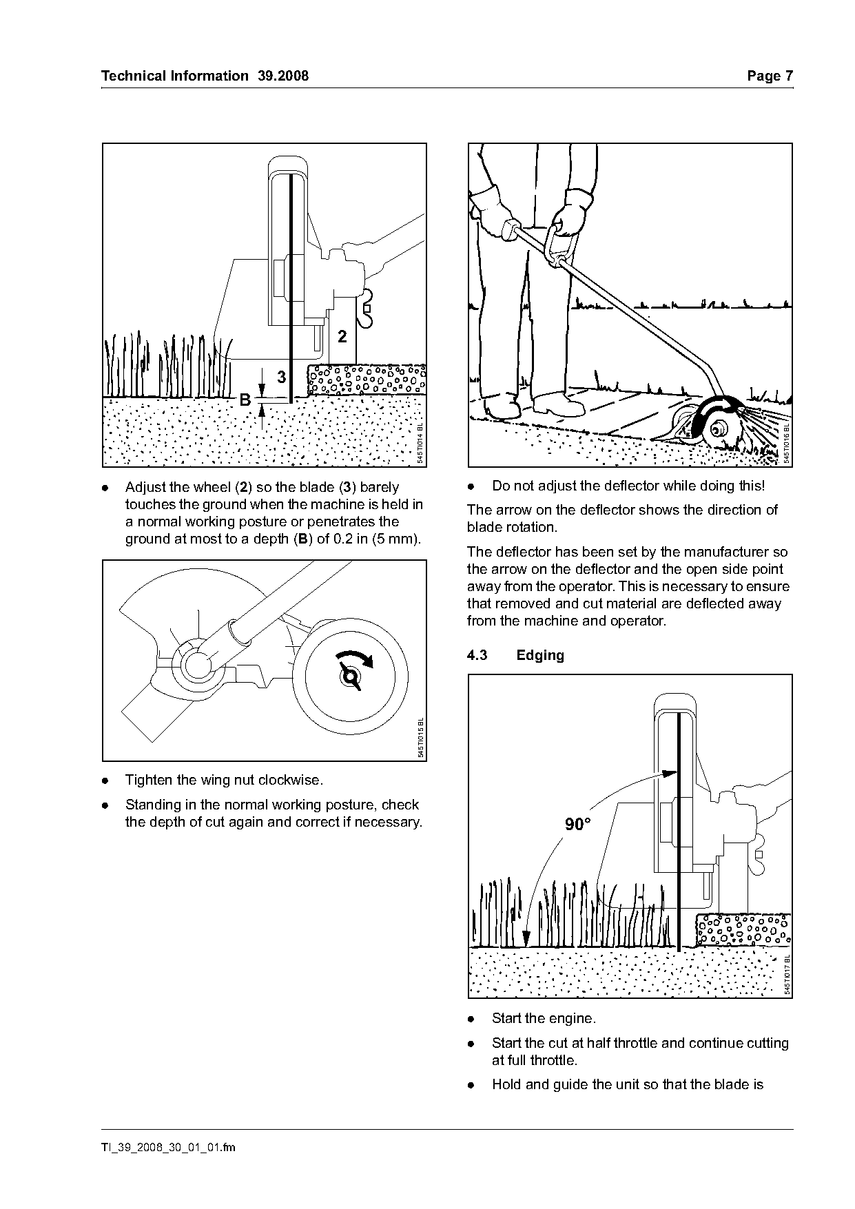
.   Adjust the wheel (2) so the blade (3) barely                .     Do not adjust the deflector while doing this!
    touches the ground when the machine is held in              The arrow on the deflector shows the direction of
    a normal working posture or penetrates the                  blade rotation.
    ground at most to a depth (B) of 0.2 in (5 mm).
                                                                The deflector has been set by the manufacturer so
                                                                the arrow on the deflector and the open side point
                                                                away from the operator. This is necessary to ensure
                                                                that removed and cut material are deflected away
                                                                from the machine and operator.

                                                                4.3       Edging
                                                  545TI015 BL

.   Tighten the wing nut clockwise.
.   Standing in the normal working posture, check
    the depth of cut again and correct if necessary.                               90°
                                                                                                                       545TI017 BL

                                                                .     Start the engine.
                                                                .     Start the cut at half throttle and continue cutting
                                                                      at full throttle.
                                                                .     Hold and guide the unit so that the blade is

TI_39_2008_30_01_01.fm
Page 8 of 15
Text of page 8 — search, copy, screen readers
Page 8                                                                                   Technical Information 39.2008

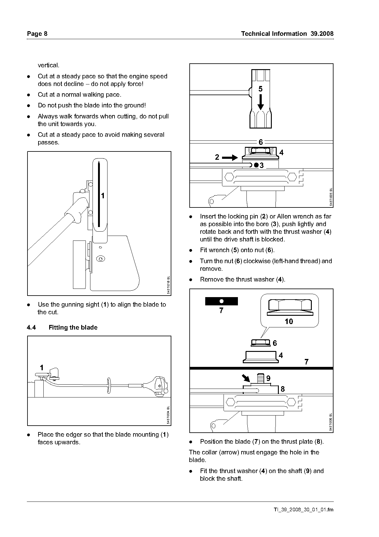
      vertical.
.     Cut at a steady pace so that the engine speed
      does not decline – do not apply force!
                                                                                                5
.     Cut at a normal walking pace.
.     Do not push the blade into the ground!
.     Always walk forwards when cutting, do not pull
      the unit towards you.
.     Cut at a steady pace to avoid making several
      passes.                                                                                   6
                                                                                                            4
                                                                               2
                                                                                                3

                                                                                                                            545TI005 BL
                              1

                                                                      .   Insert the locking pin (2) or Allen wrench as far
                                                                          as possible into the bore (3), push lightly and
                                                                          rotate back and forth with the thrust washer (4)
                                                                          until the drive shaft is blocked.
                                                                      .   Fit wrench (5) onto nut (6).
                                                                      .   Turn the nut (6) clockwise (left-hand thread) and
                                                                          remove.
                                                        545TI018 BL

                                                                      .   Remove the thrust washer (4).

.     Use the gunning sight (1) to align the blade to
      the cut.                                                                     7
                                                                                                                10
4.4       Fitting the blade

                                                                                                        6
                                                                                                            4
                                                                                                                     7
      1
                                                                                                    9
                                                                                                            8
                                                        545TI004 BL

                                                                                                                            545TI006 BL

.     Place the edger so that the blade mounting (1)
      faces upwards.                                                  .   Position the blade (7) on the thrust plate (8).
                                                                      The collar (arrow) must engage the hole in the
                                                                      blade.
                                                                      .   Fit the thrust washer (4) on the shaft (9) and
                                                                          block the shaft.

                                                                                                        TI_39_2008_30_01_01.fm
Page 9 of 15
Text of page 9 — search, copy, screen readers
Technical Information 39.2008                                                                                           Page 9

.     Screw nut (6) onto drive shaft counterclockwise                   4.6.2   Positioning the skirt
      and tighten.
If the cup spring (10) on the nut (6) becomes
fatigued, the nut must be replaced!

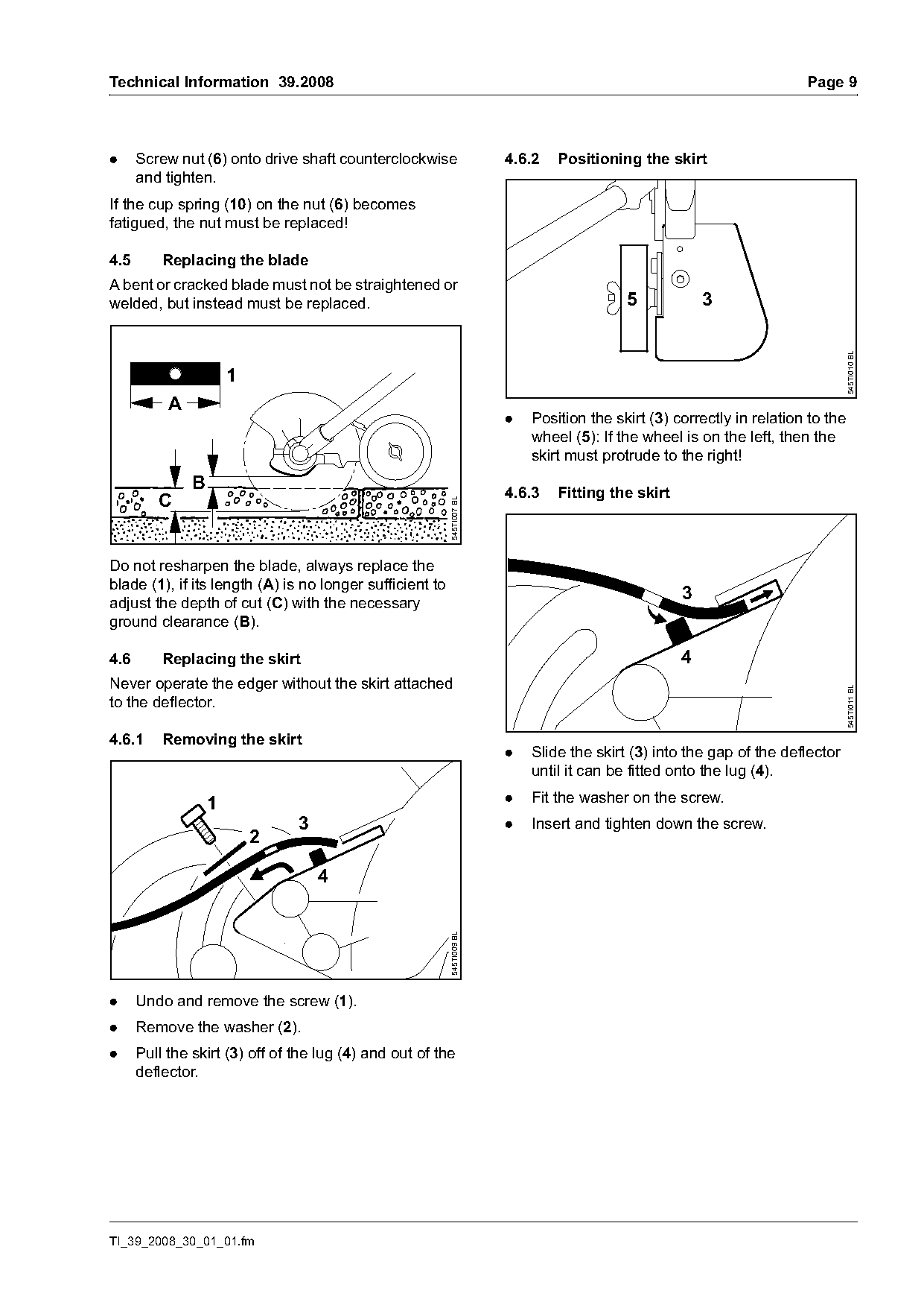
4.5       Replacing the blade
A bent or cracked blade must not be straightened or
welded, but instead must be replaced.                                                      5            3

                                                                                                                                545TI010 BL
                       1
           A
                                                                        .   Position the skirt (3) correctly in relation to the
                                                                            wheel (5): If the wheel is on the left, then the
                                                                            skirt must protrude to the right!
               B                                                        4.6.3   Fitting the skirt
         C
                                                          545TI007 BL

Do not resharpen the blade, always replace the
blade (1), if its length (A) is no longer sufficient to
                                                                                                    3
adjust the depth of cut (C) with the necessary
ground clearance (B).

4.6       Replacing the skirt                                                                       4
Never operate the edger without the skirt attached

                                                                                                                                545TI011 BL
to the deflector.

4.6.1     Removing the skirt
                                                                        .   Slide the skirt (3) into the gap of the deflector
                                                                            until it can be fitted onto the lug (4).

                   1                                                    .   Fit the washer on the screw.
                                3                                       .   Insert and tighten down the screw.
                           2

                                    4
                                                          545TI009 BL

.     Undo and remove the screw (1).
.     Remove the washer (2).
.     Pull the skirt (3) off of the lug (4) and out of the
      deflector.

TI_39_2008_30_01_01.fm
Page 10 of 15
Text of page 10 — search, copy, screen readers
Page 10                                                                              Technical Information 39.2008

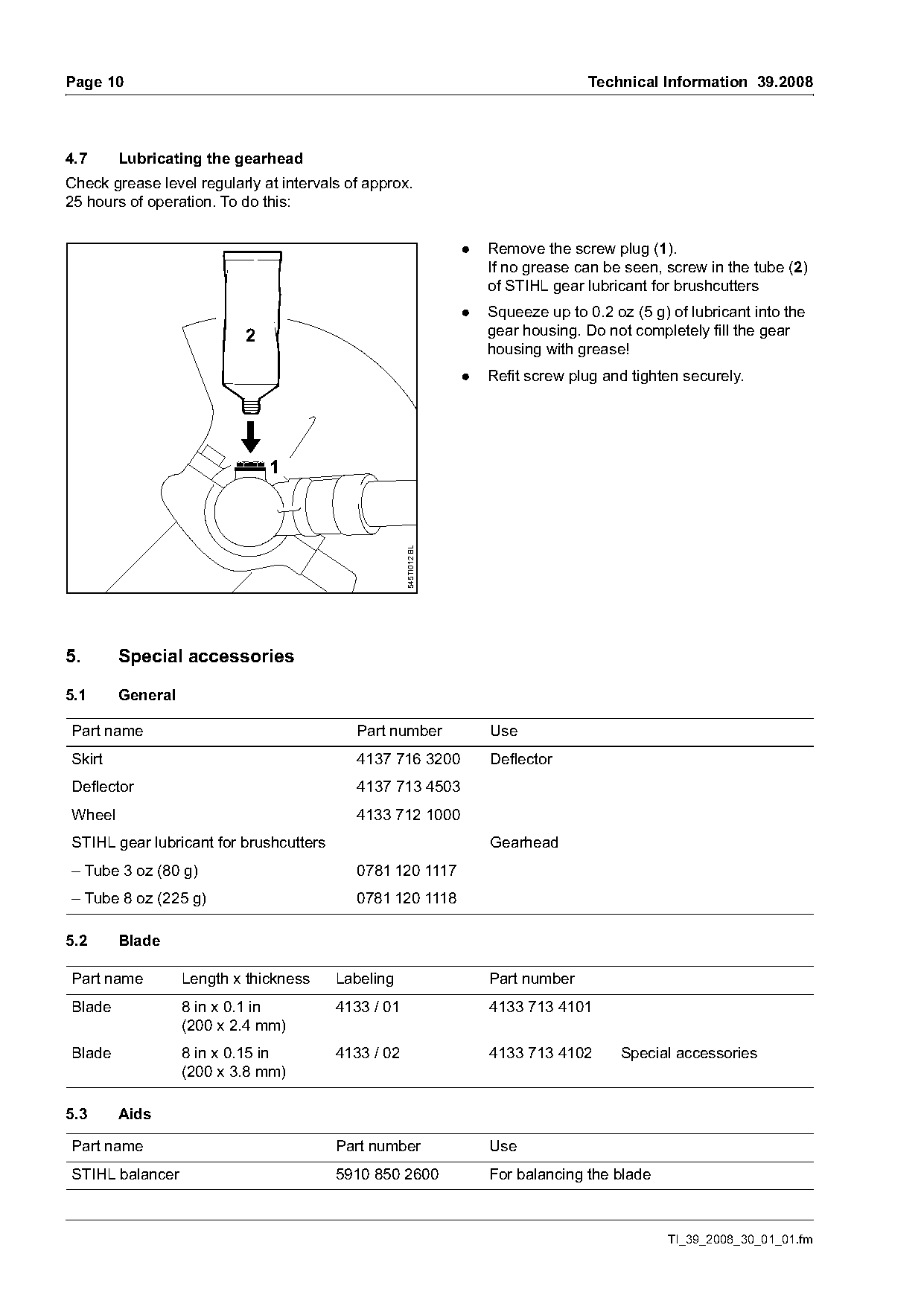
4.7     Lubricating the gearhead
Check grease level regularly at intervals of approx.
25 hours of operation. To do this:

                                                                  .   Remove the screw plug (1).
                                                                      If no grease can be seen, screw in the tube (2)
                                                                      of STIHL gear lubricant for brushcutters
                                                                  .   Squeeze up to 0.2 oz (5 g) of lubricant into the
                          2                                           gear housing. Do not completely fill the gear
                                                                      housing with grease!
                                                                  .   Refit screw plug and tighten securely.

                              1
                                                    545TI012 BL

5.      Special accessories

5.1     General

Part name                                  Part number                Use
Skirt                                      4137 716 3200              Deflector
Deflector                                  4137 713 4503
Wheel                                      4133 712 1000
STIHL gear lubricant for brushcutters                                 Gearhead
– Tube 3 oz (80 g)                         0781 120 1117
– Tube 8 oz (225 g)                        0781 120 1118

5.2     Blade

Part name         Length x thickness    Labeling                      Part number
Blade             8 in x 0.1 in         4133 / 01                     4133 713 4101
                  (200 x 2.4 mm)
Blade             8 in x 0.15 in        4133 / 02                     4133 713 4102       Special accessories
                  (200 x 3.8 mm)

5.3     Aids

Part name                               Part number                   Use
STIHL balancer                          5910 850 2600                 For balancing the blade

                                                                                                 TI_39_2008_30_01_01.fm
Page 11 of 15
Text of page 11 — search, copy, screen readers
Technical Information 39.2008                                                                          Page 11

6.         Servicing accessories

6.1        Special tools

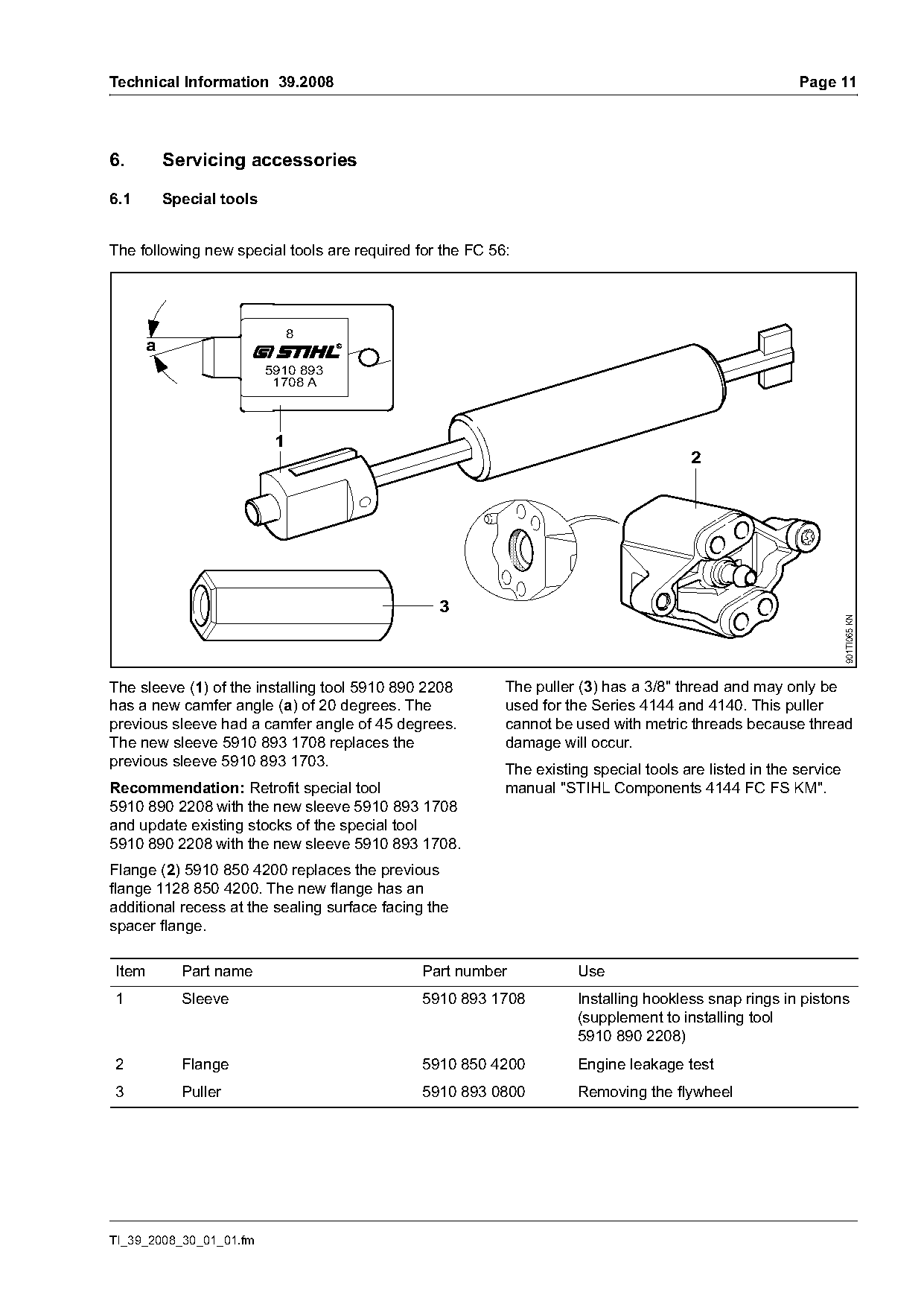
The following new special tools are required for the FC 56:

                                8
       a
                           5910 893
                            1708 A

                            1
                                                                                      2


                                                                                                                 901TI065 KN
The sleeve (1) of the installing tool 5910 890 2208       The puller (3) has a 3/8" thread and may only be
has a new camfer angle (a) of 20 degrees. The             used for the Series 4144 and 4140. This puller
previous sleeve had a camfer angle of 45 degrees.         cannot be used with metric threads because thread
The new sleeve 5910 893 1708 replaces the                 damage will occur.
previous sleeve 5910 893 1703.
                                                          The existing special tools are listed in the service
Recommendation: Retrofit special tool                     manual "STIHL Components 4144 FC FS KM".
5910 890 2208 with the new sleeve 5910 893 1708
and update existing stocks of the special tool
5910 890 2208 with the new sleeve 5910 893 1708.
Flange (2) 5910 850 4200 replaces the previous
flange 1128 850 4200. The new flange has an
additional recess at the sealing surface facing the
spacer flange.

Item         Part name                        Part number            Use
1            Sleeve                           5910 893 1708          Installing hookless snap rings in pistons
                                                                     (supplement to installing tool
                                                                     5910 890 2208)
2            Flange                           5910 850 4200          Engine leakage test
3            Puller                           5910 893 0800          Removing the flywheel

TI_39_2008_30_01_01.fm
Page 12 of 15
Text of page 12 — search, copy, screen readers
Page 12                                                                  Technical Information 39.2008

6.2    Aids

Part name                                 Part number     Use
Starter rope 35.8 in (910 mm)             4137 195 8200   Rewind starter

ElastoStart™ (special accessory)          0000 190 3403   Starter mechanism (handle with rope)
– Starter rope 35.8 in (910 mm)           4137 195 8200

Set of carburetor parts                   4241 007 1002   Carburetor Zama C1M-S145
                                                          Carburetor Zama C1M-S146 (only for
                                                          California)

STIHL gear lubricant for                                  Drive shaft in drive tube
hedge trimmers
– Tube 3 oz (80 g)                        0781 120 1109
– Tube 8 oz (225 g)                       0781 120 1110

STIHL gear lubricant for                                  Gearhead
trimmers
– Tube 3 oz (80 g)                        0781 120 1117
– Tube 8 oz (225 g)                       0781 120 1118

NEW:
STIHL fitting paste                                       Paste contains molybdenum sulfide and
– Tube 1.8 oz (50 g)                      0781 130 1014   graphite; use for lubrication between crankshaft
                                                          stub and clutch drum
Standard solvent-based degreaser not                      Cleaning the crankshaft stub and cone on the
containing any chlorinated or                             flywheel (see TI 25.2005)
halogenated hydrocarbons

7.     Spare parts
Separate spare parts documentation will be
available for FC 56 when it is launched on the
market.

                                                                                      TI_39_2008_30_01_01.fm
Page 13 of 15
Text of page 13 — search, copy, screen readers
Technical Information 39.2008                                                                           Page 13

8.        Servicing
The safety instructions in the Instruction Manual
must be observed if the machine has to be started
up during servicing.

8.1       Service manuals
The following manuals can be used for repairs to the
FC 56:

      For engine, control elements and shaft of the FC 56                                For the gearhead
                      (powerhead 4144)                                                     of the FC 56

        Repair instructions          Repair instructions                                 Repair instructions
        Powerhead 4144               Components 4144                                       KombiTools
         0455 938 0123                0455 545 0123                                       0455 227 0123

8.2       Tightening torques                                8.4      Maintenance and Repairs
The tightening torques are also specified in the
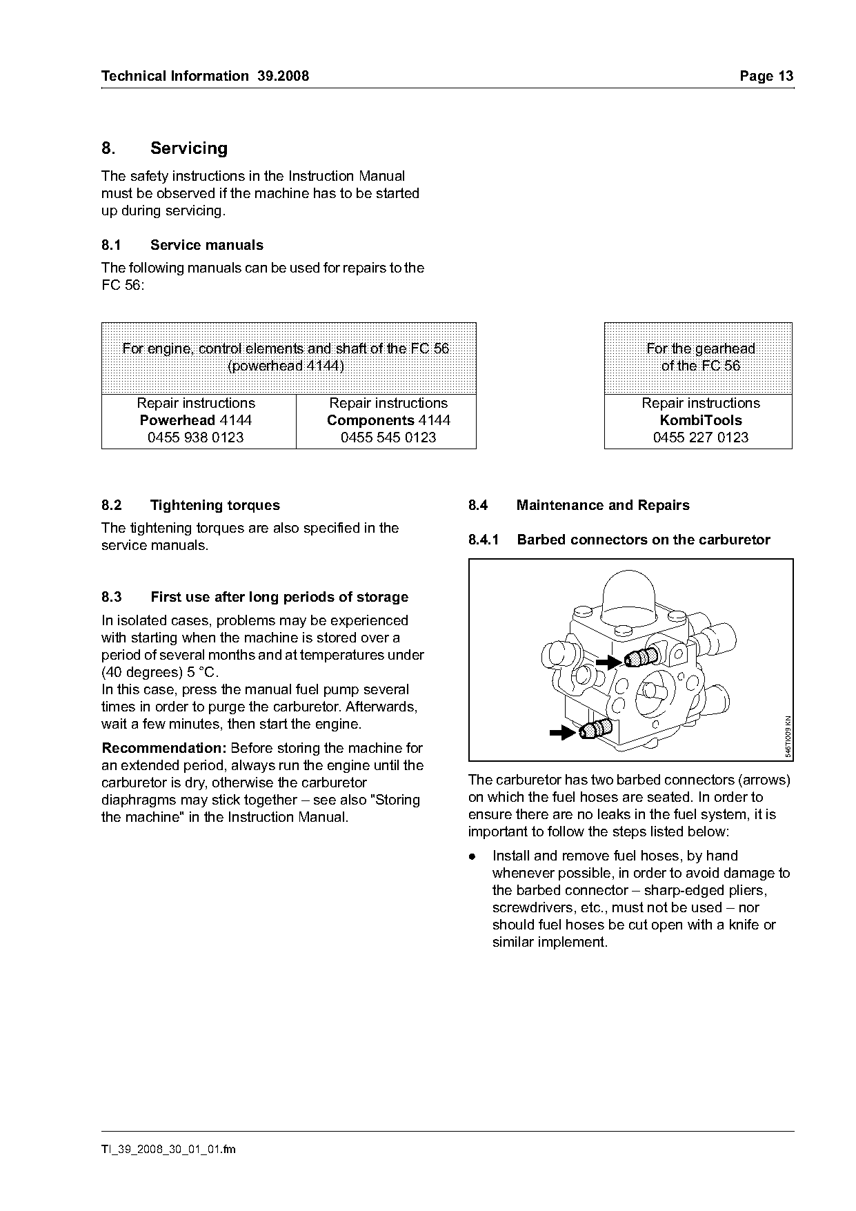
service manuals.                                            8.4.1    Barbed connectors on the carburetor

8.3       First use after long periods of storage
In isolated cases, problems may be experienced
with starting when the machine is stored over a
period of several months and at temperatures under
(40 degrees) 5 °C.
In this case, press the manual fuel pump several
times in order to purge the carburetor. Afterwards,
wait a few minutes, then start the engine.

                                                                                                               546TI009 KN
Recommendation: Before storing the machine for
an extended period, always run the engine until the
carburetor is dry, otherwise the carburetor                 The carburetor has two barbed connectors (arrows)
diaphragms may stick together – see also "Storing           on which the fuel hoses are seated. In order to
the machine" in the Instruction Manual.                     ensure there are no leaks in the fuel system, it is
                                                            important to follow the steps listed below:
                                                            .     Install and remove fuel hoses, by hand
                                                                  whenever possible, in order to avoid damage to
                                                                  the barbed connector – sharp-edged pliers,
                                                                  screwdrivers, etc., must not be used – nor
                                                                  should fuel hoses be cut open with a knife or
                                                                  similar implement.

TI_39_2008_30_01_01.fm
Page 14 of 15
Text of page 14 — search, copy, screen readers
Page 14                                                                                  Technical Information 39.2008

.   Do not reuse fuel hoses after disassembly,                      Notes regarding fitting paste: If fitting paste is not
    always replace them with new hoses – fuel                       applied to the crankshaft stub or the carburetor is
    hoses may be over-extended when removed.                        improperly adjusted, the cutting tool may rotate
                                                                    when the machine is idling.
.   Install new fuel hoses dry or with the aid of press
                                                                    If the cutting tool turns when the machine is idling,
    fluid OH 723 – 0781 957 9000. Other press
                                                                    check for proper carburetor adjustment and verify
    fluids are not permitted and may lead to fuel
                                                                    fitting paste has been applied to the crankshaft stub.
    hose damage.
.   When using press fluid OH 723, apply press                      8.5       Replacing the wheel
    fluid to the ends of the hose and connectors
                                                                    A worn or damaged wheel must be replaced.
    prior to installation.
Notes regarding press fluid OH 723                                  8.5.1     Removal
Press fluid OH 723 produces a lubricant film to aid
in assembly. The lubricant evaporates after a short
time allowing for a tight fit.
Never use fuel, oil or grease as a lubricant. Fuel, oil
and grease does not evaporate and may allow the
hose to slip from the connector.

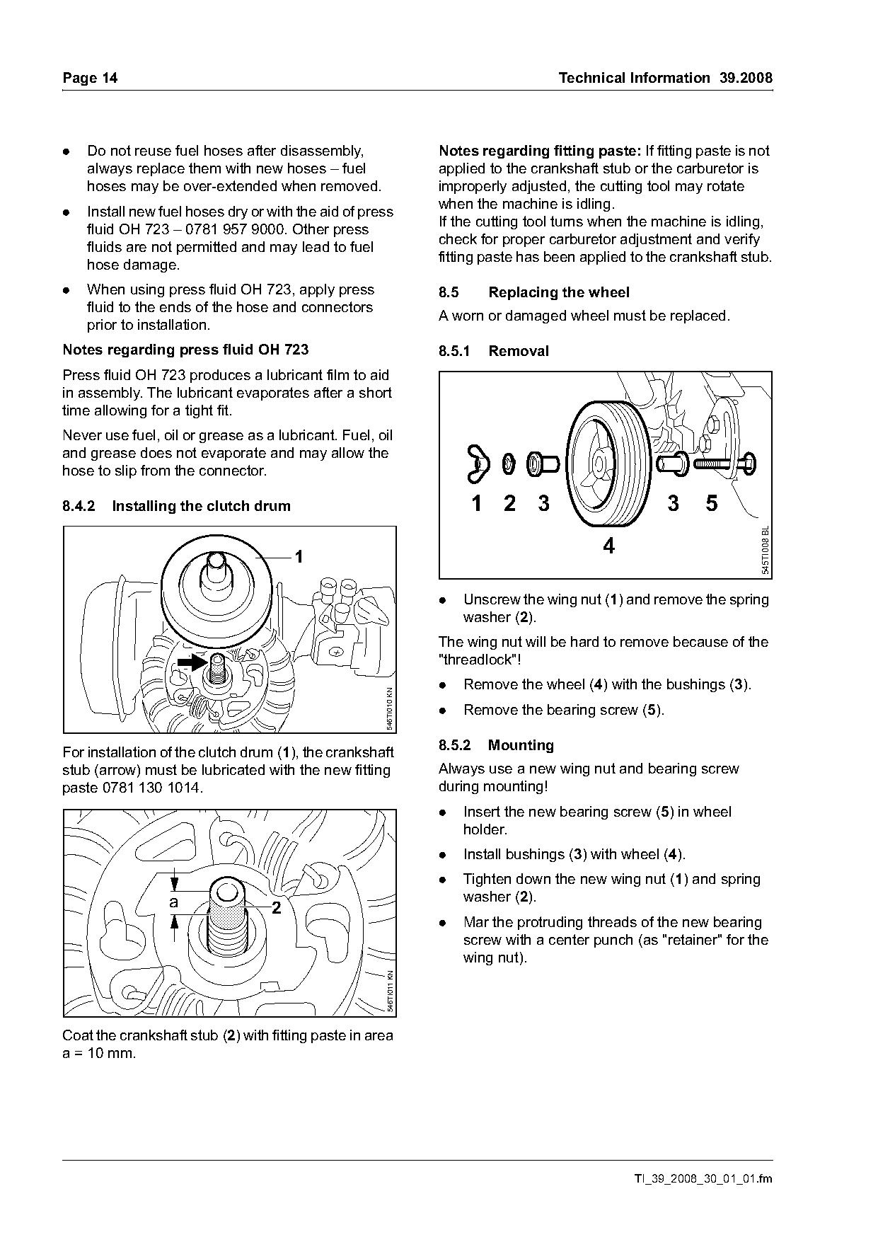
8.4.2   Installing the clutch drum                                         1 2 3                          3      5

                                                                                                                         545TI008 BL
                                      1
                                                                                                4

                                                                    .     Unscrew the wing nut (1) and remove the spring
                                                                          washer (2).
                                                                    The wing nut will be hard to remove because of the
                                                                    "threadlock"!
                                                                    .     Remove the wheel (4) with the bushings (3).
                                                     546TI010 KN

                                                                    .     Remove the bearing screw (5).

                                                                    8.5.2     Mounting
For installation of the clutch drum (1), the crankshaft
stub (arrow) must be lubricated with the new fitting                Always use a new wing nut and bearing screw
paste 0781 130 1014.                                                during mounting!
                                                                    .     Insert the new bearing screw (5) in wheel
                                                                          holder.
                                                                    .     Install bushings (3) with wheel (4).
                                                                    .     Tighten down the new wing nut (1) and spring
                 a                                                        washer (2).
                                  2
                                                                    .     Mar the protruding threads of the new bearing
                                                                          screw with a center punch (as "retainer" for the
                                                                          wing nut).
                                                      546TI011 KN

Coat the crankshaft stub (2) with fitting paste in area
a = 10 mm.

                                                                                                     TI_39_2008_30_01_01.fm
Page 15 of 15
Text of page 15 — search, copy, screen readers
Technical Information 39.2008                                                                                Page 15

8.6     Balancing the blade                                     8.8    Repair times
All edger blades should be checked with the STIHL               The specified repair times apply for trained and
balancer to see if they are out-of-balance and – if             qualified personnel as well as for properly equipped
necessary – rebalanced or replace.                              repair shops.
                                                                The repair times are specified in minutes.
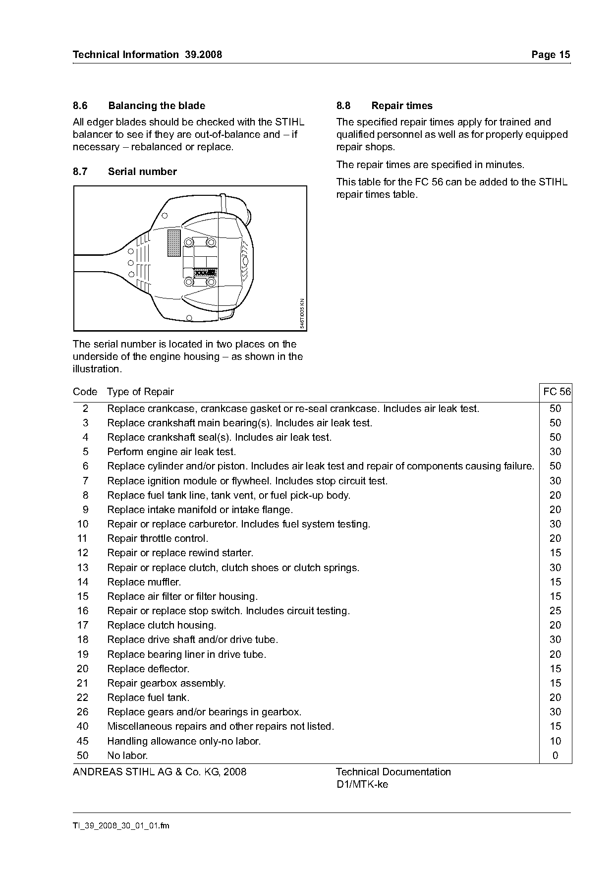
8.7     Serial number
                                                                This table for the FC 56 can be added to the STIHL
                                                                repair times table.

                                                  546TI005 KN

The serial number is located in two places on the
underside of the engine housing – as shown in the
illustration.

Code Type of Repair                                                                                            FC 56
 2     Replace crankcase, crankcase gasket or re-seal crankcase. Includes air leak test.                        50
 3     Replace crankshaft main bearing(s). Includes air leak test.                                              50
 4     Replace crankshaft seal(s). Includes air leak test.                                                      50
 5     Perform engine air leak test.                                                                            30
 6     Replace cylinder and/or piston. Includes air leak test and repair of components causing failure.         50
 7     Replace ignition module or flywheel. Includes stop circuit test.                                         30
 8     Replace fuel tank line, tank vent, or fuel pick-up body.                                                 20
 9     Replace intake manifold or intake flange.                                                                20
10     Repair or replace carburetor. Includes fuel system testing.                                              30
11     Repair throttle control.                                                                                 20
12     Repair or replace rewind starter.                                                                        15
13     Repair or replace clutch, clutch shoes or clutch springs.                                                30
14     Replace muffler.                                                                                         15
15     Replace air filter or filter housing.                                                                    15
16     Repair or replace stop switch. Includes circuit testing.                                                 25
17     Replace clutch housing.                                                                                  20
18     Replace drive shaft and/or drive tube.                                                                   30
19     Replace bearing liner in drive tube.                                                                     20
20     Replace deflector.                                                                                       15
21     Repair gearbox assembly.                                                                                 15
22     Replace fuel tank.                                                                                       20
26     Replace gears and/or bearings in gearbox.                                                                30
40     Miscellaneous repairs and other repairs not listed.                                                      15
45     Handling allowance only-no labor.                                                                        10
50     No labor.                                                                                                 0
ANDREAS STIHL AG & Co. KG, 2008                                 Technical Documentation
                                                                D1/MTK-ke

TI_39_2008_30_01_01.fm
Most of these PDFs embed fonts with a shifted character map, so the text above was recovered rather than copied — read it as a faithful but imperfect transcription, and treat the page image above each block as the authority where the two disagree — the figures exist only there, because they are vector drawings that text extraction cannot keep.