Technical Information · issue 5 of 2009
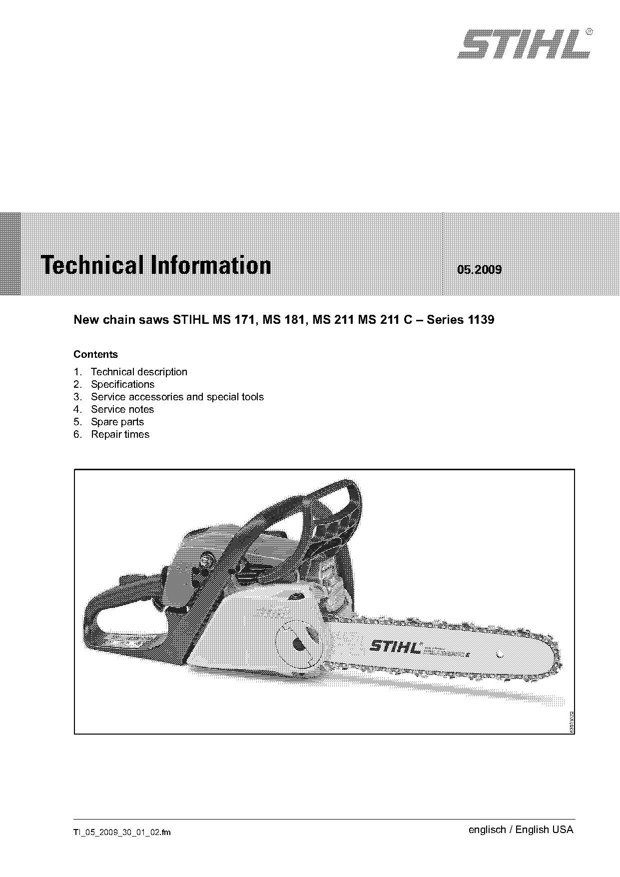
New chain saws STIHL MS 171, MS 181, MS 211 MS 211 C
IssueTI 5/2009
Engine family 1139
Full text
Page 1 of 14
Text of page 1 — search, copy, screen readers
STIH)

Technical Information                                         05.2009

  New chain saws STIHL MS 171, MS 181, MS 211 MS 211 C – Series 1139

  Contents
  1.   Technical description
  2.   Specifications
  3.   Service accessories and special tools
  4.   Service notes
  5.   Spare parts
  6.   Repair times

  TI_05_2009_30_01_02.fm                                       englisch / English USA
Page 2 of 14
Text of page 2 — search, copy, screen readers
Page 2                                                                        Technical Information 05.2009

Excellent power, reduced vibration and fuel efficient:   1.         Technical description
these are the characteristic features distinguishing
the new STIHL chain saw models MS 171, MS 181,           1.1       2-cycle engine with stratified scavenging
MS 211 and MS 211 C.
                                                         A cushion of fuel-free air separates the unburned
The new STIHL 2-cycle engine with four-port              fuel-air mixture from the exhaust gas. This cushion
technology and stratified scavenging ensures:            of air is located in front of the unburned fuel-air
-   Higher power levels and performance                  mixture. At the start of the exhaust and scavenging
                                                         cycle, fuel-free air enters from the transfer ports into
-   Consistant torque over a wide speed range            the combustion chamber and scavenges the
-   Lower fuel consumption – up to 20 % as               exhaust gas into the exhaust port. The fuel-free air
    compared with conventional 2-stroke engines          prevents the unburned fuel-air mixture from entering
                                                         the exhaust port, thus reducing scavenging losses
                                                         and fuel consumption.
The MS 171, MS 181, MS 211 and MS 211 C are
designed and built for:
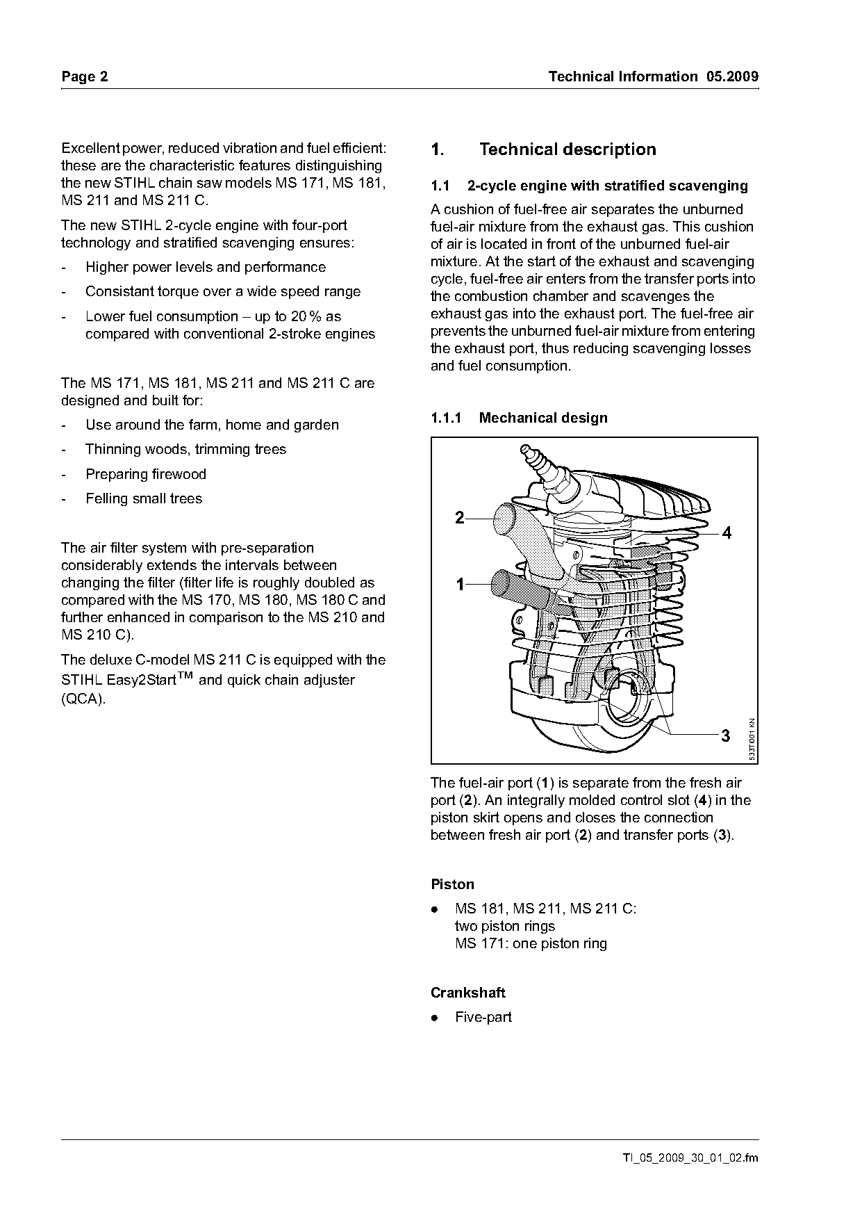
                                                         1.1.1      Mechanical design
-   Use around the farm, home and garden
-   Thinning woods, trimming trees
-   Preparing firewood
-   Felling small trees
                                                               2
                                                                                                           4
The air filter system with pre-separation
considerably extends the intervals between
changing the filter (filter life is roughly doubled as         1
compared with the MS 170, MS 180, MS 180 C and
further enhanced in comparison to the MS 210 and
MS 210 C).
The deluxe C-model MS 211 C is equipped with the
STIHL Easy2Start™ and quick chain adjuster
(QCA).

                                                                                                               533TI001 KN
                                                                                                          3

                                                         The fuel-air port (1) is separate from the fresh air
                                                         port (2). An integrally molded control slot (4) in the
                                                         piston skirt opens and closes the connection
                                                         between fresh air port (2) and transfer ports (3).

                                                         Piston
                                                         .     MS 181, MS 211, MS 211 C:
                                                               two piston rings
                                                               MS 171: one piston ring

                                                         Crankshaft
                                                         .     Five-part

                                                                                          TI_05_2009_30_01_02.fm
Page 3 of 14
Text of page 3 — search, copy, screen readers
Technical Information 05.2009                                                                                          Page 3

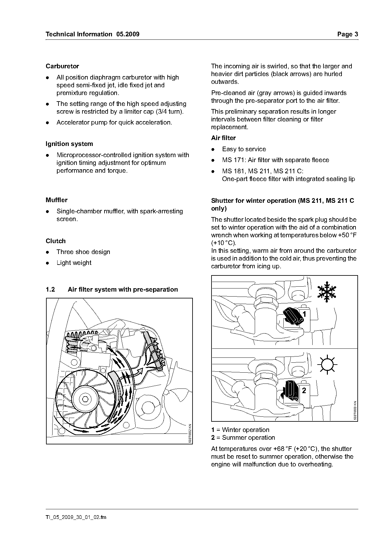
Carburetor                                                             The incoming air is swirled, so that the larger and
                                                                       heavier dirt particles (black arrows) are hurled
.     All position diaphragm carburetor with high
                                                                       outwards.
      speed semi-fixed jet, idle fixed jet and
      premixture regulation.                                           Pre-cleaned air (gray arrows) is guided inwards
.     The setting range of the high speed adjusting                    through the pre-separator port to the air filter.
      screw is restricted by a limiter cap (3/4 turn).                 This preliminary separation results in longer
                                                                       intervals between filter cleaning or filter
.     Accelerator pump for quick acceleration.
                                                                       replacement.
                                                                       Air filter
Ignition system
                                                                       .   Easy to service
.     Microprocessor-controlled ignition system with
      ignition timing adjustment for optimum                           .   MS 171: Air filter with separate fleece
      performance and torque.                                          .   MS 181, MS 211, MS 211 C:
                                                                           One-part fleece filter with integrated sealing lip

Muffler                                                                Shutter for winter operation (MS 211, MS 211 C
.     Single-chamber muffler, with spark-arresting                     only)
      screen.                                                          The shutter located beside the spark plug should be
                                                                       set to winter operation with the aid of a combination
                                                                       wrench when working at temperatures below +50 °F
Clutch                                                                 (+10 °C).
.     Three shoe design                                                In this setting, warm air from around the carburetor
                                                                       is used in addition to the cold air, thus preventing the
.     Light weight
                                                                       carburetor from icing up.

1.2       Air filter system with pre-separation


                                                                                                          2
                                                                                                                             533TI003 KN
                                                         533TI002 KN

                                                                       1 = Winter operation
                                                                       2 = Summer operation
                                                                       At temperatures over +68 °F (+20 °C), the shutter
                                                                       must be reset to summer operation, otherwise the
                                                                       engine will malfunction due to overheating.

TI_05_2009_30_01_02.fm
Page 4 of 14
Text of page 4 — search, copy, screen readers
Page 4                                                                                  Technical Information 05.2009

1.3       Anti-vibration system                                     Quick chain adjuster
                                                                    .     Quick and easy tensioning of the saw chain
                                                                          without tools

                                                                    1.6      C-models with manual fuel pump

                                                      533TI004 KN
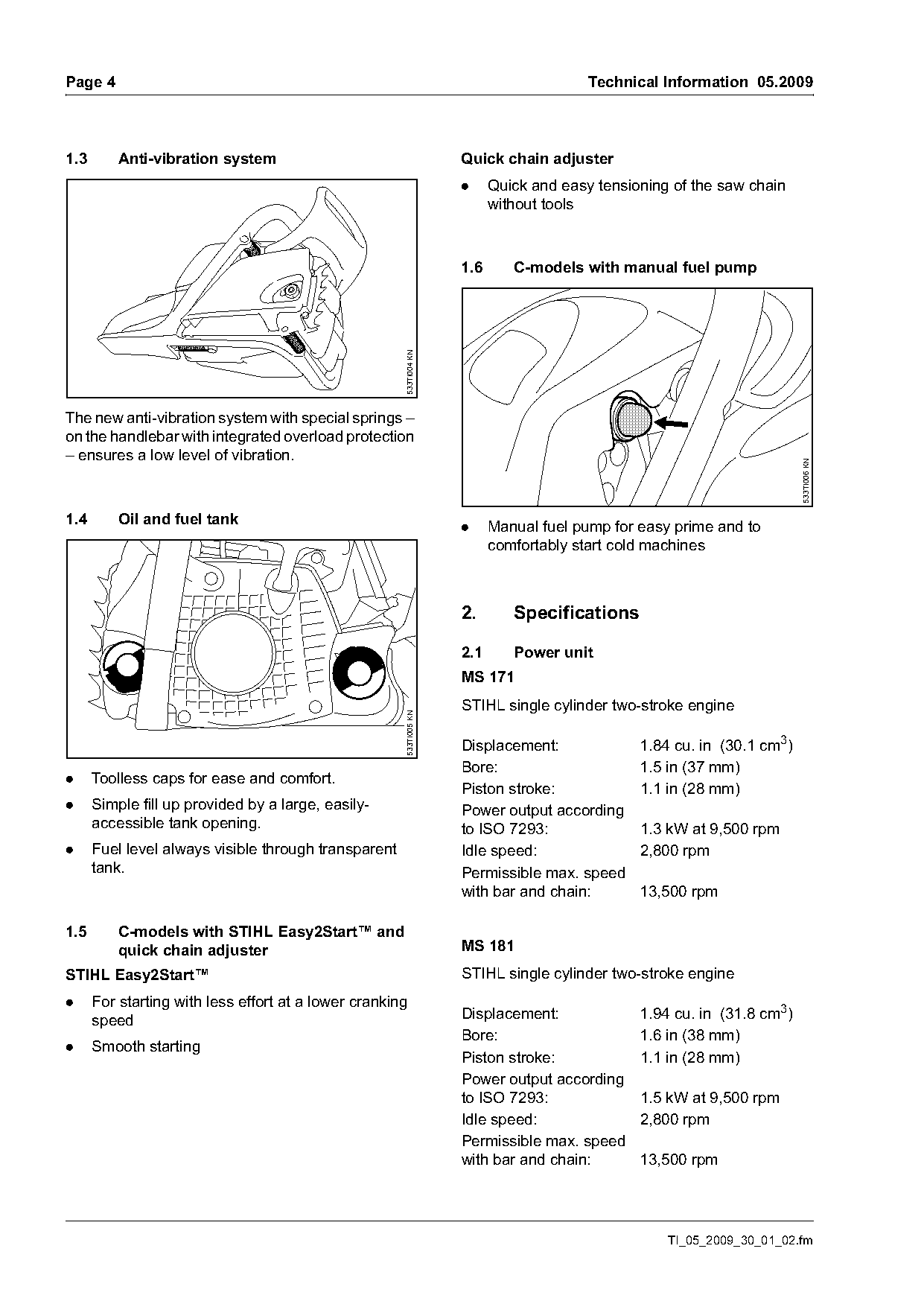
The new anti-vibration system with special springs –
on the handlebar with integrated overload protection
– ensures a low level of vibration.

                                                                                                                        533TI006 KN
1.4       Oil and fuel tank                                         .     Manual fuel pump for easy prime and to
                                                                          comfortably start cold machines

                                                                    2.       Specifications

                                                                    2.1      Power unit
                                                                    MS 171
                                                                    STIHL single cylinder two-stroke engine
                                                      533TI005 KN

                                                                    Displacement:              1.84 cu. in (30.1 cm3)
                                                                    Bore:                      1.5 in (37 mm)
.     Toolless caps for ease and comfort.
                                                                    Piston stroke:             1.1 in (28 mm)
.     Simple fill up provided by a large, easily-                   Power output according
      accessible tank opening.                                      to ISO 7293:               1.3 kW at 9,500 rpm
.     Fuel level always visible through transparent                 Idle speed:                2,800 rpm
      tank.                                                         Permissible max. speed
                                                                    with bar and chain:        13,500 rpm

1.5       C-models with STIHL Easy2Start™ and
          quick chain adjuster                                      MS 181
STIHL Easy2Start™                                                   STIHL single cylinder two-stroke engine
.     For starting with less effort at a lower cranking
      speed                                                         Displacement:              1.94 cu. in (31.8 cm3)
                                                                    Bore:                      1.6 in (38 mm)
.     Smooth starting
                                                                    Piston stroke:             1.1 in (28 mm)
                                                                    Power output according
                                                                    to ISO 7293:               1.5 kW at 9,500 rpm
                                                                    Idle speed:                2,800 rpm
                                                                    Permissible max. speed
                                                                    with bar and chain:        13,500 rpm

                                                                                                   TI_05_2009_30_01_02.fm
Page 5 of 14
Text of page 5 — search, copy, screen readers
Technical Information 05.2009                                                                       Page 5

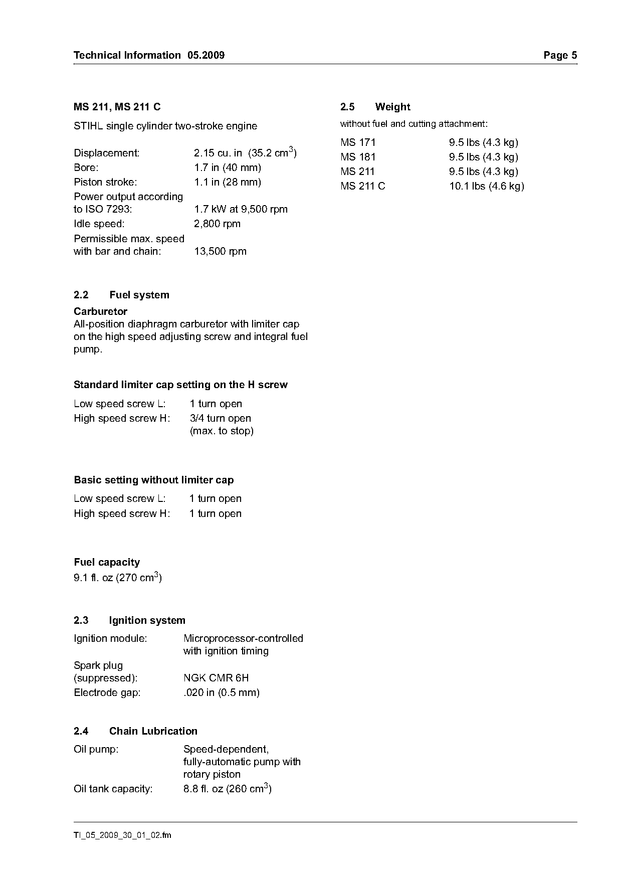
MS 211, MS 211 C                                      2.5     Weight
STIHL single cylinder two-stroke engine               without fuel and cutting attachment:
                                                      MS 171                    9.5 lbs (4.3 kg)
Displacement:              2.15 cu. in (35.2 cm3)     MS 181                    9.5 lbs (4.3 kg)
Bore:                      1.7 in (40 mm)             MS 211                    9.5 lbs (4.3 kg)
Piston stroke:             1.1 in (28 mm)             MS 211 C                  10.1 lbs (4.6 kg)
Power output according
to ISO 7293:               1.7 kW at 9,500 rpm
Idle speed:                2,800 rpm
Permissible max. speed
with bar and chain:        13,500 rpm

2.2     Fuel system
Carburetor
All-position diaphragm carburetor with limiter cap
on the high speed adjusting screw and integral fuel
pump.

Standard limiter cap setting on the H screw
Low speed screw L:        1 turn open
High speed screw H:       3/4 turn open
                          (max. to stop)

Basic setting without limiter cap
Low speed screw L:        1 turn open
High speed screw H:       1 turn open

Fuel capacity
9.1 fl. oz (270 cm3)

2.3     Ignition system
Ignition module:         Microprocessor-controlled
                         with ignition timing
Spark plug
(suppressed):            NGK CMR 6H
Electrode gap:           .020 in (0.5 mm)

2.4     Chain Lubrication
Oil pump:                Speed-dependent,
                         fully-automatic pump with
                         rotary piston
Oil tank capacity:       8.8 fl. oz (260 cm3)

TI_05_2009_30_01_02.fm
Page 6 of 14
Text of page 6 — search, copy, screen readers
Page 6                                                                    Technical Information 05.2009

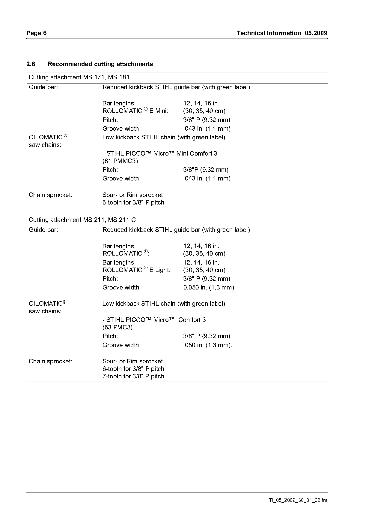
2.6      Recommended cutting attachments

Cutting attachment MS 171, MS 181
Guide bar:               Reduced kickback STIHL guide bar (with green label)

                         Bar lengths:               12, 14, 16 in.
                         ROLLOMATIC ® E Mini:       (30, 35, 40 cm)
                         Pitch:                     3/8" P (9.32 mm)
                         Groove width:              .043 in. (1.1 mm)
OILOMATIC ®              Low kickback STIHL chain (with green label)
saw chains:
                         - STIHL PICCO™ Micro™ Mini Comfort 3
                         (61 PMMC3)
                         Pitch:                  3/8"P (9.32 mm)
                         Groove width:           .043 in. (1.1 mm)

Chain sprocket:          Spur- or Rim sprocket
                         6-tooth for 3/8" P pitch

Cutting attachment MS 211, MS 211 C
Guide bar:               Reduced kickback STIHL guide bar (with green label)

                         Bar lengths                 12, 14, 16 in.
                         ROLLOMATIC ®:               (30, 35, 40 cm)
                         Bar lengths                 12, 14, 16 in.
                         ROLLOMATIC ® E Light:       (30, 35, 40 cm)
                         Pitch:                      3/8" P (9.32 mm)
                         Groove width:               0.050 in. (1,3 mm)

OILOMATIC®               Low kickback STIHL chain (with green label)
saw chains:
                         - STIHL PICCO™ Micro™ Comfort 3
                         (63 PMC3)
                         Pitch:                 3/8" P (9.32 mm)
                         Groove width:          .050 in. (1,3 mm).

Chain sprocket:          Spur- or Rim sprocket
                         6-tooth for 3/8" P pitch
                         7-tooth for 3/8“ P pitch

                                                                                    TI_05_2009_30_01_02.fm
Page 7 of 14
Text of page 7 — search, copy, screen readers
Technical Information 05.2009                                                                        Page 7

3.     Service accessories and
       special tools

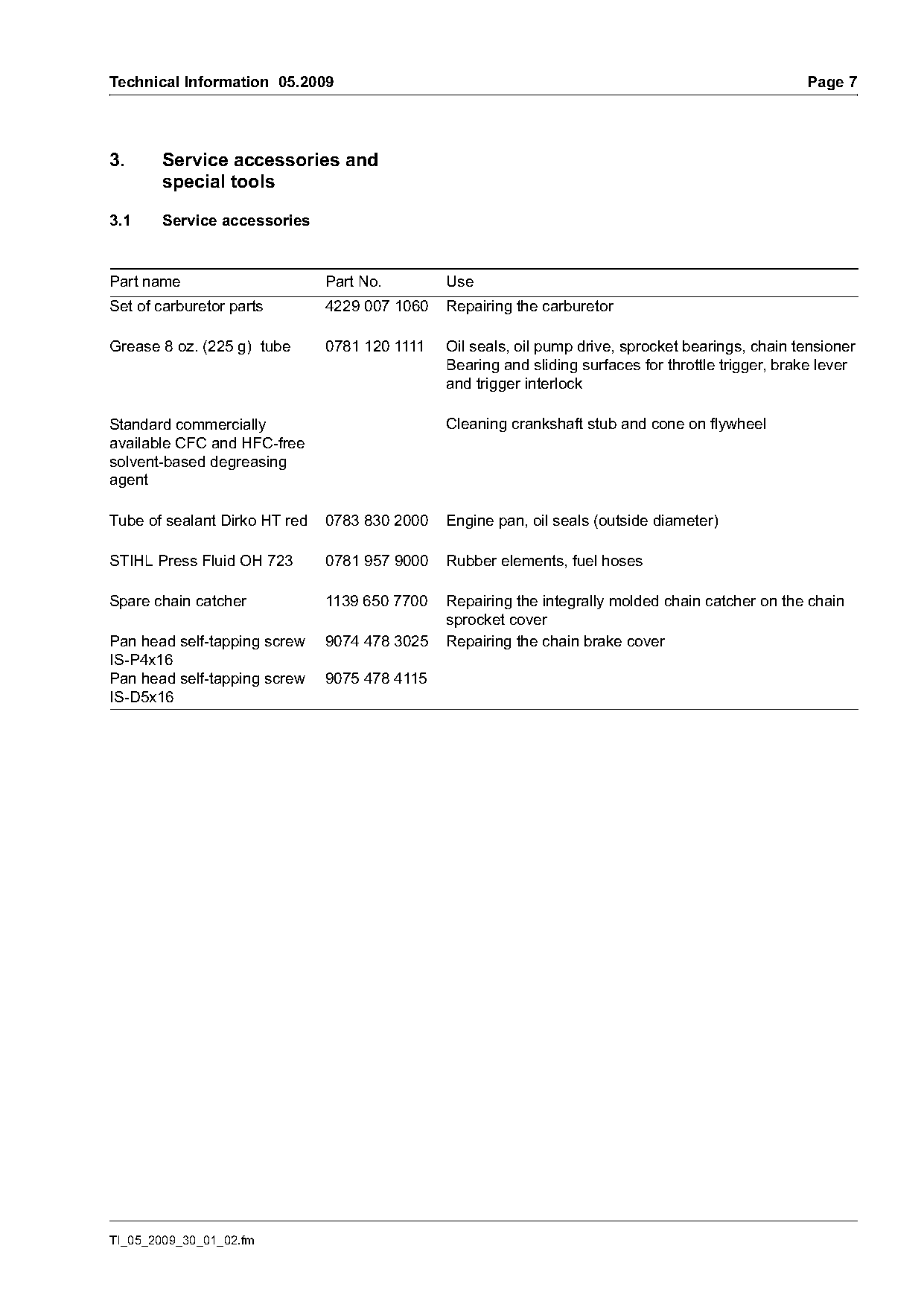
3.1     Service accessories

Part name                      Part No.        Use
Set of carburetor parts        4229 007 1060   Repairing the carburetor

Grease 8 oz. (225 g) tube      0781 120 1111   Oil seals, oil pump drive, sprocket bearings, chain tensioner
                                               Bearing and sliding surfaces for throttle trigger, brake lever
                                               and trigger interlock

Standard commercially                          Cleaning crankshaft stub and cone on flywheel
available CFC and HFC-free
solvent-based degreasing
agent

Tube of sealant Dirko HT red   0783 830 2000   Engine pan, oil seals (outside diameter)

STIHL Press Fluid OH 723       0781 957 9000   Rubber elements, fuel hoses

Spare chain catcher            1139 650 7700   Repairing the integrally molded chain catcher on the chain
                                               sprocket cover
Pan head self-tapping screw    9074 478 3025   Repairing the chain brake cover
IS-P4x16
Pan head self-tapping screw    9075 478 4115
IS-D5x16

TI_05_2009_30_01_02.fm
Page 8 of 14
Text of page 8 — search, copy, screen readers
Page 8                                                                     Technical Information 05.2009

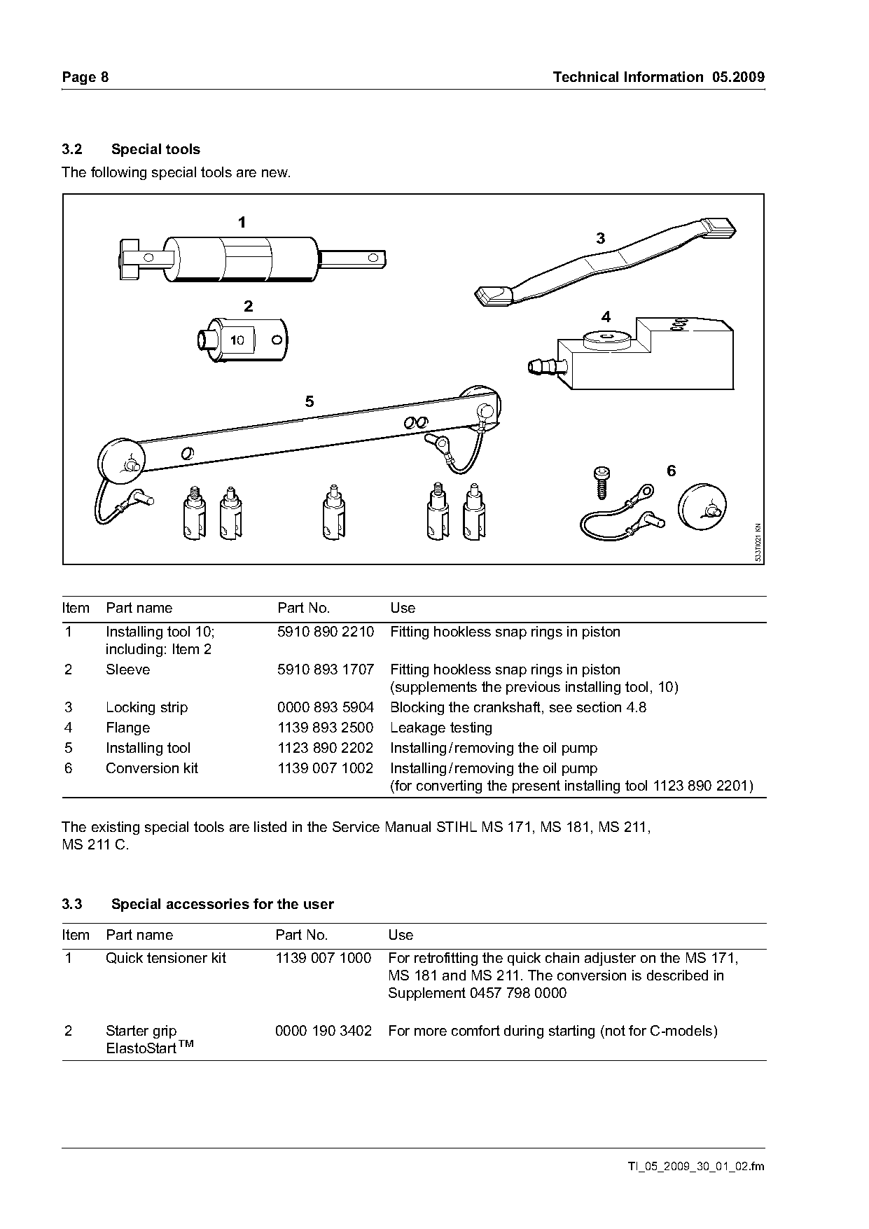
3.2      Special tools
The following special tools are new.

                             1
                                                                                  3

                             2
                                                                                   4


                                                                                                              533TI021 KN
Item   Part name                 Part No.        Use
1      Installing tool 10;       5910 890 2210   Fitting hookless snap rings in piston
       including: Item 2
2      Sleeve                    5910 893 1707   Fitting hookless snap rings in piston
                                                 (supplements the previous installing tool, 10)
3      Locking strip             0000 893 5904   Blocking the crankshaft, see section 4.8
4      Flange                    1139 893 2500   Leakage testing
5      Installing tool           1123 890 2202   Installing / removing the oil pump
6      Conversion kit            1139 007 1002   Installing / removing the oil pump
                                                 (for converting the present installing tool 1123 890 2201)

The existing special tools are listed in the Service Manual STIHL MS 171, MS 181, MS 211,
MS 211 C.

3.3      Special accessories for the user

Item   Part name                 Part No.        Use
1      Quick tensioner kit       1139 007 1000   For retrofitting the quick chain adjuster on the MS 171,
                                                 MS 181 and MS 211. The conversion is described in
                                                 Supplement 0457 798 0000

2      Starter grip              0000 190 3402   For more comfort during starting (not for C-models)
       ElastoStart™

                                                                                         TI_05_2009_30_01_02.fm
Page 9 of 14
Text of page 9 — search, copy, screen readers
Technical Information 05.2009                                                                                     Page 9

4.        Service notes                                           4.2       Maintenance / repair

All safety regulations and safety instructions in the
Instruction Manual must be observed if the chain
saw has to be started up during servicing.

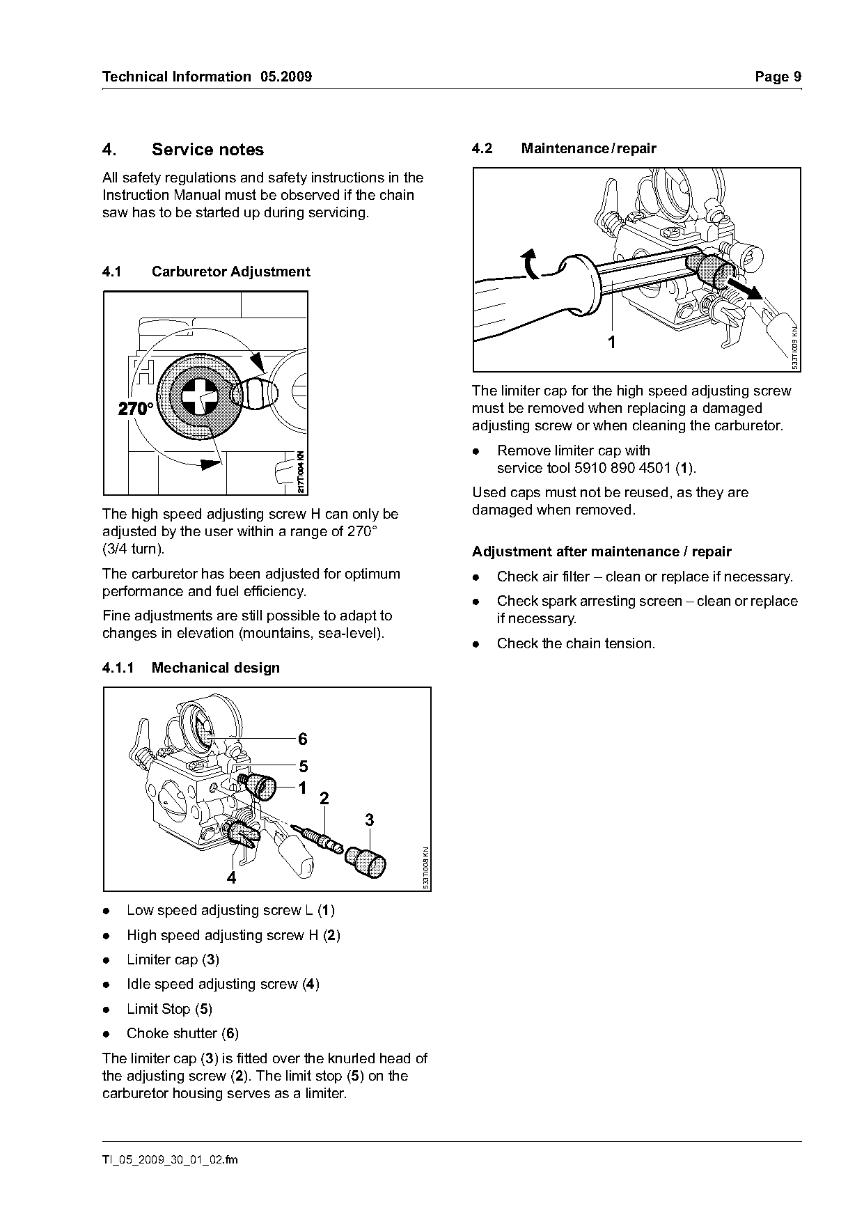
4.1       Carburetor Adjustment

                                                                                                                        533TI009 KN
                                                                                          1

                                                                  The limiter cap for the high speed adjusting screw
                                                                  must be removed when replacing a damaged
                                                                  adjusting screw or when cleaning the carburetor.
                                                                  .     Remove limiter cap with
                                                                        service tool 5910 890 4501 (1).
                                                                  Used caps must not be reused, as they are
The high speed adjusting screw H can only be                      damaged when removed.
adjusted by the user within a range of 270°
(3/4 turn).                                                       Adjustment after maintenance / repair
The carburetor has been adjusted for optimum                      .     Check air filter – clean or replace if necessary.
performance and fuel efficiency.
                                                                  .     Check spark arresting screen – clean or replace
Fine adjustments are still possible to adapt to                         if necessary.
changes in elevation (mountains, sea-level).
                                                                  .     Check the chain tension.
4.1.1     Mechanical design

                                6
                                5
                                1
                                    2
                                           3
                                                    533TI008 KN

                        4
.     Low speed adjusting screw L (1)
.     High speed adjusting screw H (2)
.     Limiter cap (3)
.     Idle speed adjusting screw (4)
.     Limit Stop (5)
.     Choke shutter (6)
The limiter cap (3) is fitted over the knurled head of
the adjusting screw (2). The limit stop (5) on the
carburetor housing serves as a limiter.

TI_05_2009_30_01_02.fm
Page 10 of 14
Text of page 10 — search, copy, screen readers
Page 10                                                                       Technical Information 05.2009

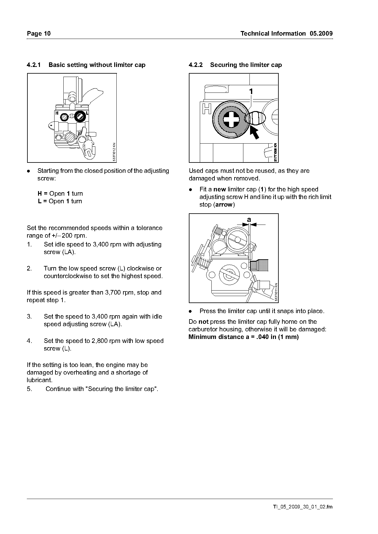
4.2.1    Basic setting without limiter cap                4.2.2   Securing the limiter cap

                                 533TI012 KN

.    Starting from the closed position of the adjusting   Used caps must not be reused, as they are
     screw:                                               damaged when removed.
                                                          .   Fit a new limiter cap (1) for the high speed
     H = Open 1 turn
                                                              adjusting screw H and line it up with the rich limit
     L = Open 1 turn
                                                              stop (arrow)

                                                                                a
Set the recommended speeds within a tolerance
range of +/– 200 rpm.
1.    Set idle speed to 3,400 rpm with adjusting
      screw (LA).

2.      Turn the low speed screw (L) clockwise or
        counterclockwise to set the highest speed.                                         533TI011 KN

If this speed is greater than 3,700 rpm, stop and
repeat step 1.
                                                          .   Press the limiter cap until it snaps into place.
3.      Set the speed to 3,400 rpm again with idle
        speed adjusting screw (LA).                       Do not press the limiter cap fully home on the
                                                          carburetor housing, otherwise it will be damaged:
                                                          Minimum distance a = .040 in (1 mm)
4.      Set the speed to 2,800 rpm with low speed
        screw (L).

If the setting is too lean, the engine may be
damaged by overheating and a shortage of
lubricant.
5.      Continue with "Securing the limiter cap".

                                                                                           TI_05_2009_30_01_02.fm
Page 11 of 14
Text of page 11 — search, copy, screen readers
Technical Information 05.2009                                                                                    Page 11

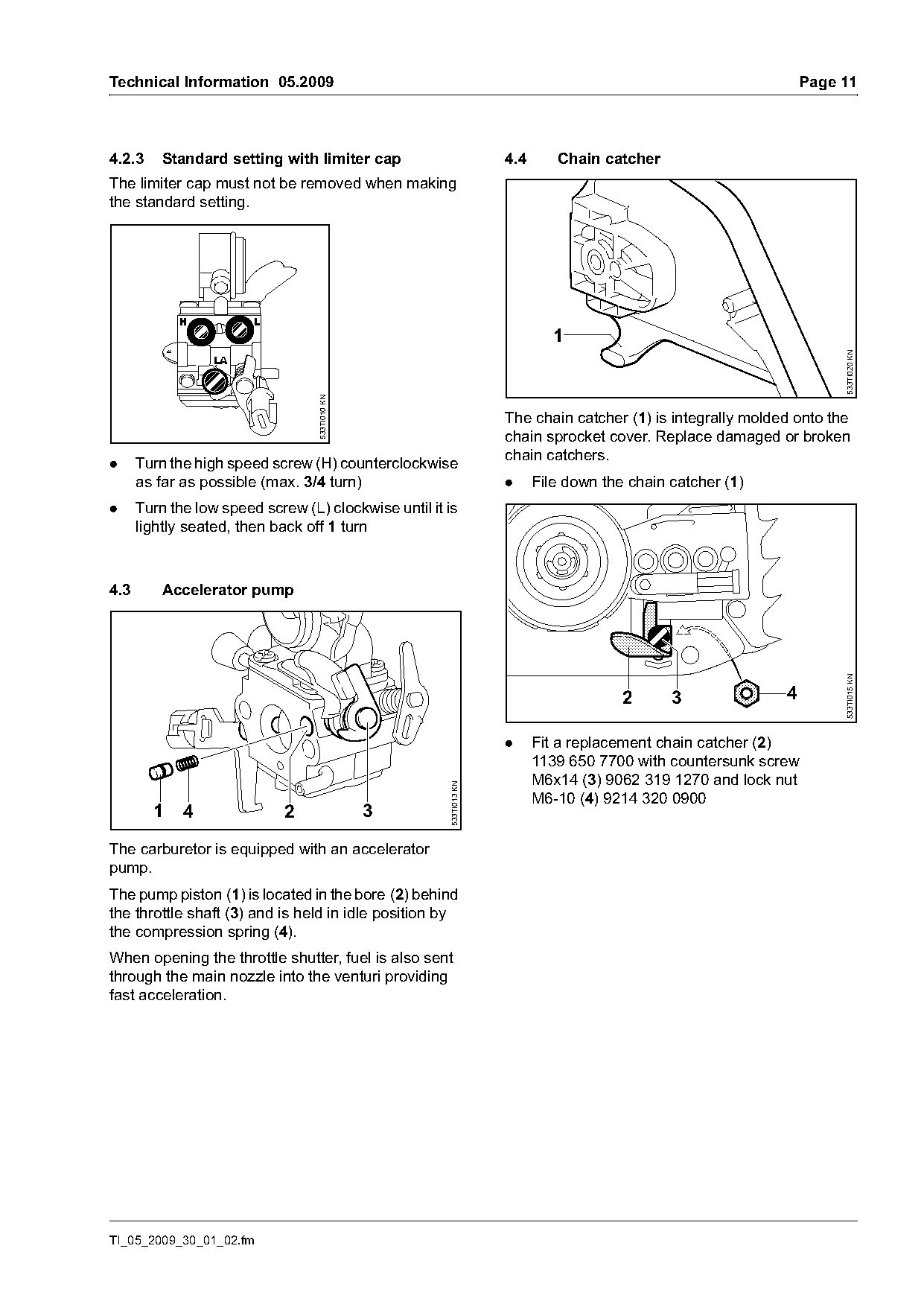
4.2.3     Standard setting with limiter cap                         4.4      Chain catcher
The limiter cap must not be removed when making
the standard setting.


                                                                                                                      533TI020 KN
                                  533TI010 KN

                                                                    The chain catcher (1) is integrally molded onto the
                                                                    chain sprocket cover. Replace damaged or broken
                                                                    chain catchers.
.     Turn the high speed screw (H) counterclockwise
      as far as possible (max. 3/4 turn)                            .     File down the chain catcher (1)
.     Turn the low speed screw (L) clockwise until it is
      lightly seated, then back off 1 turn

4.3       Accelerator pump

                                                                                                                      533TI015 KN
                                                                                       2      3              4

                                                                    .     Fit a replacement chain catcher (2)
                                                                          1139 650 7700 with countersunk screw
                                                                          M6x14 (3) 9062 319 1270 and lock nut
                                                      533TI013 KN

                                                                          M6-10 (4) 9214 320 0900
        1    4               2                  3

The carburetor is equipped with an accelerator
pump.
The pump piston (1) is located in the bore (2) behind
the throttle shaft (3) and is held in idle position by
the compression spring (4).
When opening the throttle shutter, fuel is also sent
through the main nozzle into the venturi providing
fast acceleration.

TI_05_2009_30_01_02.fm
Page 12 of 14
Text of page 12 — search, copy, screen readers
Page 12                                                                                    Technical Information 05.2009

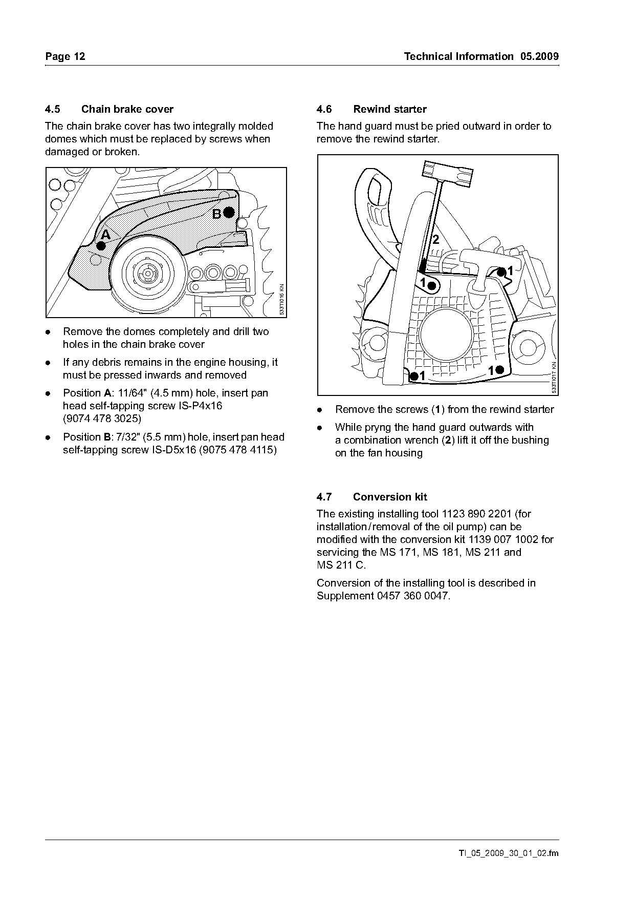
4.5      Chain brake cover                                            4.6       Rewind starter
The chain brake cover has two integrally molded                       The hand guard must be pried outward in order to
domes which must be replaced by screws when                           remove the rewind starter.
damaged or broken.


                                                                                                                  1
                                                        533TI016 KN
                                                                                              1

.     Remove the domes completely and drill two
      holes in the chain brake cover
.     If any debris remains in the engine housing, it

                                                                                                                               533TI017 KN
      must be pressed inwards and removed                                                     1               1
.     Position A: 11/64" (4.5 mm) hole, insert pan
      head self-tapping screw IS-P4x16                                .     Remove the screws (1) from the rewind starter
      (9074 478 3025)
                                                                      .     While pryng the hand guard outwards with
.     Position B: 7/32" (5.5 mm) hole, insert pan head                      a combination wrench (2) lift it off the bushing
      self-tapping screw IS-D5x16 (9075 478 4115)                           on the fan housing

                                                                      4.7       Conversion kit
                                                                      The existing installing tool 1123 890 2201 (for
                                                                      installation / removal of the oil pump) can be
                                                                      modified with the conversion kit 1139 007 1002 for
                                                                      servicing the MS 171, MS 181, MS 211 and
                                                                      MS 211 C.
                                                                      Conversion of the installing tool is described in
                                                                      Supplement 0457 360 0047.

                                                                                                       TI_05_2009_30_01_02.fm
Page 13 of 14
Text of page 13 — search, copy, screen readers
Technical Information 05.2009                                                                                   Page 13

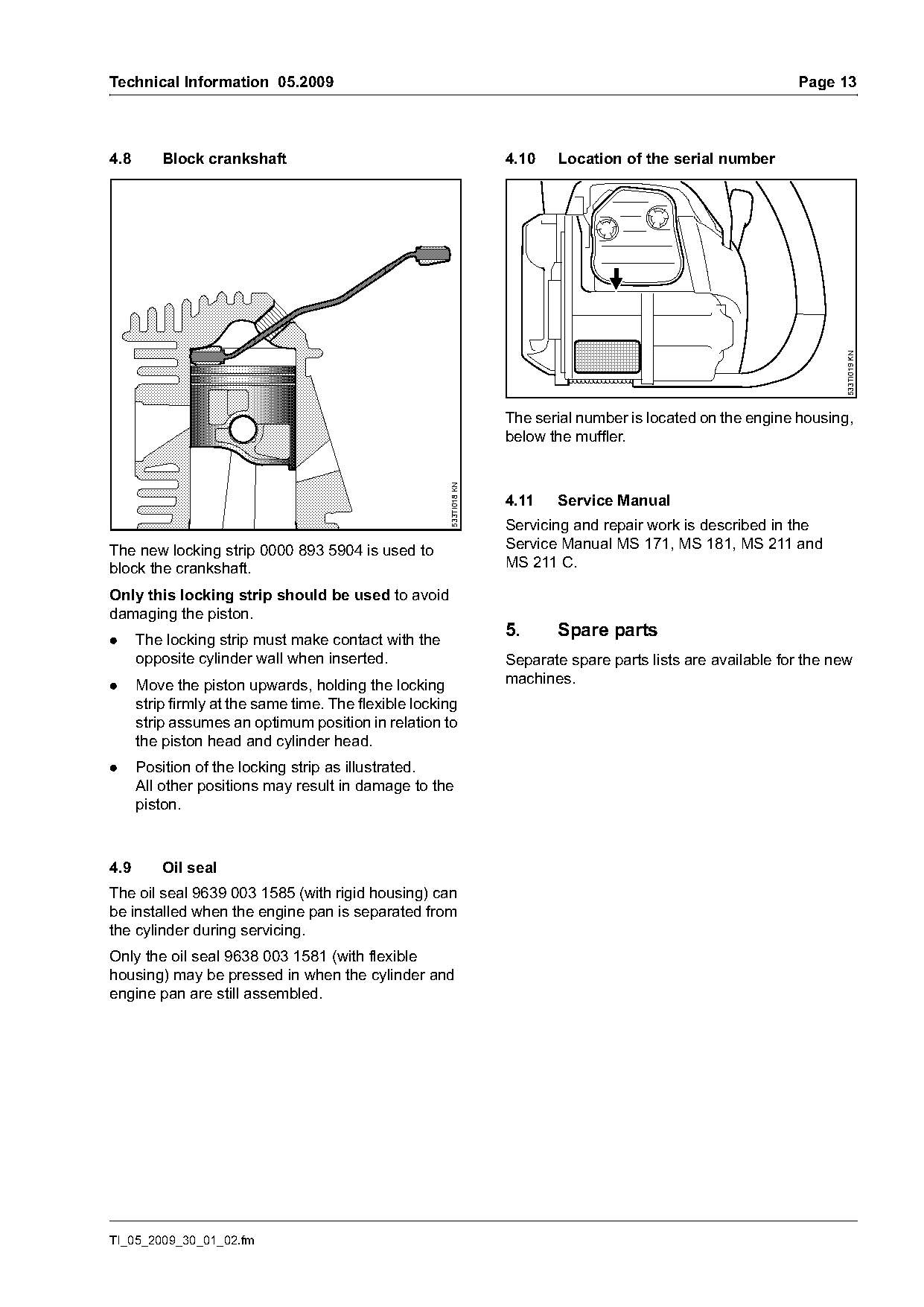
4.8       Block crankshaft                                           4.10   Location of the serial number

                                                                                                                        533TI019 KN
                                                                     The serial number is located on the engine housing,
                                                                     below the muffler.
                                                       533TI018 KN

                                                                     4.11   Service Manual
                                                                     Servicing and repair work is described in the
The new locking strip 0000 893 5904 is used to                       Service Manual MS 171, MS 181, MS 211 and
block the crankshaft.                                                MS 211 C.

Only this locking strip should be used to avoid
damaging the piston.
.     The locking strip must make contact with the
                                                                     5.     Spare parts
      opposite cylinder wall when inserted.                          Separate spare parts lists are available for the new
.     Move the piston upwards, holding the locking                   machines.
      strip firmly at the same time. The flexible locking
      strip assumes an optimum position in relation to
      the piston head and cylinder head.
.     Position of the locking strip as illustrated.
      All other positions may result in damage to the
      piston.

4.9       Oil seal
The oil seal 9639 003 1585 (with rigid housing) can
be installed when the engine pan is separated from
the cylinder during servicing.
Only the oil seal 9638 003 1581 (with flexible
housing) may be pressed in when the cylinder and
engine pan are still assembled.

TI_05_2009_30_01_02.fm
Page 14 of 14
Text of page 14 — search, copy, screen readers
Page 14                                                                      Technical Information 05.2009

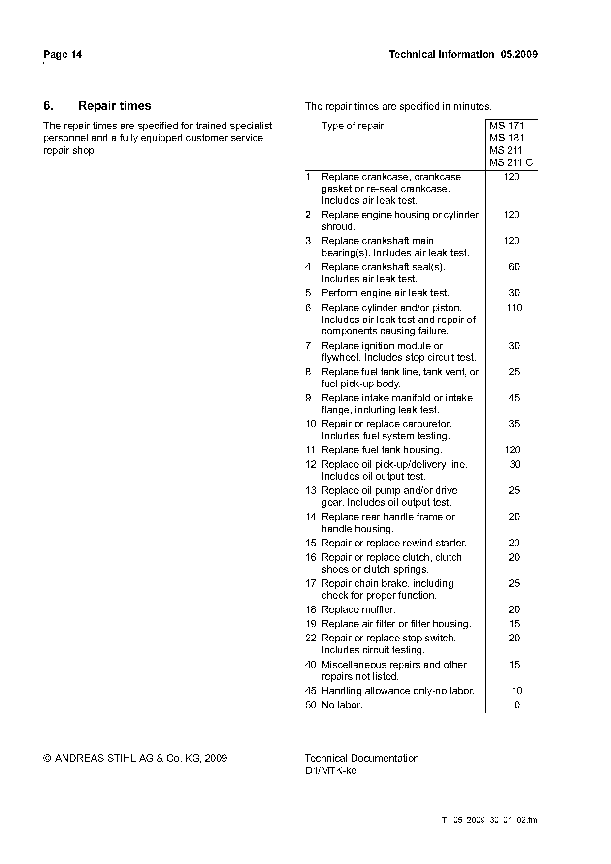
6.      Repair times                                    The repair times are specified in minutes.
The repair times are specified for trained specialist       Type of repair                         MS 171
personnel and a fully equipped customer service                                                    MS 181
repair shop.                                                                                       MS 211
                                                                                                   MS 211 C
                                                        1  Replace crankcase, crankcase              120
                                                           gasket or re-seal crankcase.
                                                           Includes air leak test.
                                                        2 Replace engine housing or cylinder         120
                                                           shroud.
                                                        3 Replace crankshaft main                    120
                                                           bearing(s). Includes air leak test.
                                                        4 Replace crankshaft seal(s).                 60
                                                           Includes air leak test.
                                                        5 Perform engine air leak test.               30
                                                        6 Replace cylinder and/or piston.             110
                                                           Includes air leak test and repair of
                                                           components causing failure.
                                                        7 Replace ignition module or                  30
                                                           flywheel. Includes stop circuit test.
                                                        8 Replace fuel tank line, tank vent, or       25
                                                           fuel pick-up body.
                                                        9 Replace intake manifold or intake           45
                                                           flange, including leak test.
                                                        10 Repair or replace carburetor.              35
                                                           Includes fuel system testing.
                                                        11 Replace fuel tank housing.                120
                                                        12 Replace oil pick-up/delivery line.         30
                                                           Includes oil output test.
                                                        13 Replace oil pump and/or drive              25
                                                           gear. Includes oil output test.
                                                        14 Replace rear handle frame or               20
                                                           handle housing.
                                                        15 Repair or replace rewind starter.          20
                                                        16 Repair or replace clutch, clutch           20
                                                           shoes or clutch springs.
                                                        17 Repair chain brake, including              25
                                                           check for proper function.
                                                        18 Replace muffler.                           20
                                                        19 Replace air filter or filter housing.      15
                                                        22 Repair or replace stop switch.             20
                                                           Includes circuit testing.
                                                        40 Miscellaneous repairs and other            15
                                                           repairs not listed.
                                                        45 Handling allowance only-no labor.           10
                                                        50 No labor.                                   0

© ANDREAS STIHL AG & Co. KG, 2009                       Technical Documentation
                                                        D1/MTK-ke

                                                                                       TI_05_2009_30_01_02.fm
Most of these PDFs embed fonts with a shifted character map, so the text above was recovered rather than copied — read it as a faithful but imperfect transcription, and treat the page image above each block as the authority where the two disagree — the figures exist only there, because they are vector drawings that text extraction cannot keep.