Technical Information · issue 9 of 2009
Model update; Crankcase, muffler, gasket, bumper spike; Cylinder with piston, manifold; Flywheel, ignition module, wiring harness, screw; Tank housing, screw; Carburetor, grommet; Summary
IssueTI 9/2009
Engine family 1124
Part changes (10)
| Was | Becomes | What the bulletin says |
|---|---|---|
| 1124 029 0510 | 1124 029 0501 | As part of a model update the MS 880 will be The previous crankcase gasket 1124 029 0510 is equipped with a new ignition module with electronic being replaced by the version 1124 029 0501. |
| 1124 140 0625 | 1124 140 0604 | 1 Muffler with spark arresting screen The previous one-piece aluminum muffler with The previous muffler 1124 140 0625 is being tension spring and tension wedge for mounting on replaced by the version 1124 140 0604. |
| 1124 664 0501 | 1124 664 0502 | 1 Bumper spike The previous bumper spike 1124 664 0501 is being replaced by the version 1124 664 0502. |
| 1124 020 1207 | 1124 020 1209 | 1 Cylinder with piston, decompression valve, manifold The previous cylinder with piston 1124 020 1207 is being replaced by the version 1124 020 1209. |
| 1124 141 2201 | 1124 141 2202 | Flywheel, ignition module, The previous manifold 1124 141 2201 is being wiring harness, screw replaced by the version 1124 141 2202. |
| 1124 400 1210 | 1124 400 1201 | 1 Flywheel The previous polymer/aluminum composite flywheel 1124 400 1210 is being replaced by an aluminum version 1124 400 1201. |
| 1124 440 1101 | 1124 440 3000 | 3 Wiring harness (short circuit and ground wire) The previous short circuit wire 1124 440 1101 and ground wire 1124 440 2200 are being replaced by the wiring harness 1124 440 3000. |
| 1124 350 0821 | 1124 350 0823 | The previous tank housing 1124 350 0821 is being replaced by the version 1124 350 0823. |
| 1124 123 7501 | 1124 123 7502 | 2 Grommet The new double lever consists of throttle rod and The previous grommet 1124 123 7501 is being double lever and is distinguished by a throttle rod replaced by the version 1124 123 7502. |
| 1124 182 1500 | 1124 180 4050 | 3 Throttle rod, double lever The previous throttle rod 1124 182 1500 and the previous double lever 1124 182 0800 are being replaced by the version 1124 180 4050. |
Full text
Page 1 of 11
Text of page 1 — search, copy, screen readers
STIH)

Technical Information                                                               09.2009

  Chain saw STIHL MS 880 – Series 1124

  Contents
  1.    Model update
  2.    Crankcase, muffler, gasket, bumper spike
  3.    Cylinder with piston, manifold
  4.    Flywheel, ignition module, wiring harness, screw
  5.    Tank housing, screw
  6.    Carburetor, grommet
  7.    Summary

  1.       Model update                                    2.2    Gasket

  As part of a model update the MS 880 will be             The previous crankcase gasket 1124 029 0510 is
  equipped with a new ignition module with electronic      being replaced by the version 1124 029 0501.
  ignition timing and a new two-piece stainless steel      The new gasket is adapted to the changed
  muffler.                                                 geometry of the crankcase halves 1124 020 2601
                                                           and 1124 020 2903.
  2.     Crankcase, muffler, gasket, bumper
         spike                                             2.3    Service note
                                                           During servicing, the new crankcase halves can be
  2.1      Crankcase                                       replaced individually, whereas the previous design
                                                           crankcase 1124 020 2116 must be replaced with a
  The previous crankcase 1124 020 2116 is being
                                                           set.
  replaced by the crankcase half (ignition side)
  1124 020 2601 and the crankcase half (clutch side)
                                                           2.4    Spare parts
  1124 020 2903.
                                                           The previous crankcase 1124 020 2116 and the
  The new crankcase halves are distinguished by
                                                           previous gasket 1124 029 0510 remain available for
  changed mounting points for the muffler and the
                                                           older machines along with the previous muffler and
  ignition module.
                                                           ignition module mounts.

  TI_09_2009_30_01_01.fm                                                                   englisch / English
Page 2 of 11
Text of page 2 — search, copy, screen readers
Page 2                                                                                Technical Information 09.2009

2.5       Muffler                                               2.5.1   Muffler with spark arresting screen
The previous one-piece aluminum muffler with                    The previous muffler 1124 140 0625 is being
tension spring and tension wedge for mounting on                replaced by the version 1124 140 0604.
the cylinder is being replaced by a two-piece
stainless steel muffler fastened with screws.                   2.5.2   Muffler gasket
The new muffler is fastened to the exhaust flange of            The previous muffler gasket 1124 149 0610 is being
the cylinder with screws.                                       replaced by the version 1124 149 0601.
The cylinder exhaust flange and the crankcase have
                                                                2.5.3   Spare parts/service note
been modified to adapt to the muffler.
                                                                The previous muffler, muffler gasket and mounting
                                                                hardware (tension spring, tension wedge, support)
                                                                remain available for older machines.
                                                                The new mufflers can only be combined with the
                                                                new cylinder and crankcase.
                                     3
                                         1                      2.6     Bumper spike, screws

                                                                2.6.1   Bumper spike
                                                                The previous bumper spike 1124 664 0501 is being
                                                                replaced by the version 1124 664 0502. The
                                                                thickness of the new bumper spike was increased
                                                                by 0.06 in. to 0.17 in. (1.5 mm to 3.5 mm).

                               4
      2                                      67
                                                  216TI015 KN


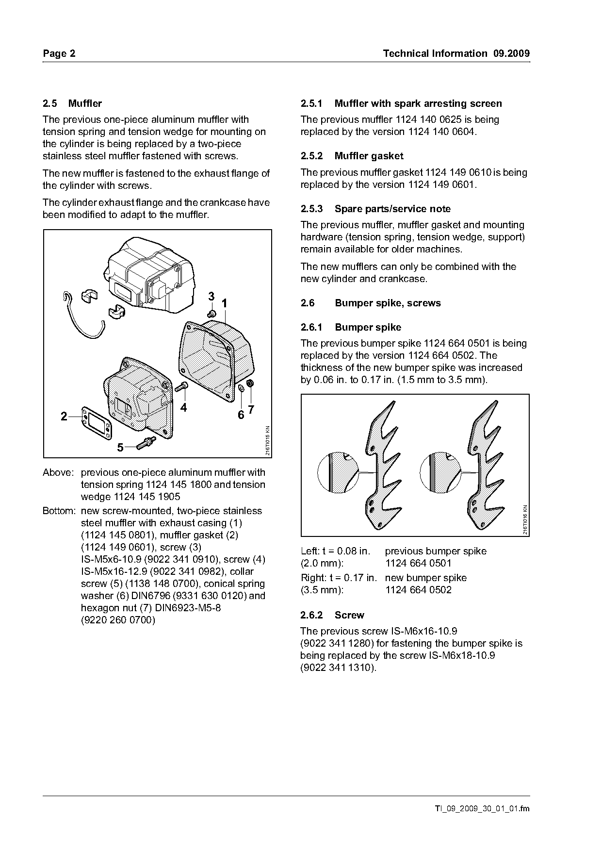
Above: previous one-piece aluminum muffler with
        tension spring 1124 145 1800 and tension
        wedge 1124 145 1905
Bottom: new screw-mounted, two-piece stainless
        steel muffler with exhaust casing (1)                                                                       216TI016 KN

        (1124 145 0801), muffler gasket (2)
        (1124 149 0601), screw (3)                              Left: t = 0.08 in.    previous bumper spike
        IS-M5x6-10.9 (9022 341 0910), screw (4)                 (2.0 mm):             1124 664 0501
        IS-M5x16-12.9 (9022 341 0982), collar
                                                                Right: t = 0.17 in.   new bumper spike
        screw (5) (1138 148 0700), conical spring
                                                                (3.5 mm):             1124 664 0502
        washer (6) DIN6796 (9331 630 0120) and
        hexagon nut (7) DIN6923-M5-8
                                                                2.6.2   Screw
        (9220 260 0700)
                                                                The previous screw IS-M6x16-10.9
                                                                (9022 341 1280) for fastening the bumper spike is
                                                                being replaced by the screw IS-M6x18-10.9
                                                                (9022 341 1310).

                                                                                                TI_09_2009_30_01_01.fm
Page 3 of 11
Text of page 3 — search, copy, screen readers
Technical Information 09.2009                                                                             Page 3

2.6.3    Spare parts/service note                                3.2      Decompression valve
The previous bumper spike 1124 664 0501                          The previous decompression valve 1124 020 9410
(t = 0.08 in. (2.0 mm)) will no longer be available.             is being replaced by the version 1124 020 9401.
The new bumper spike 1124 664 0502 (t = 0.17 in.                 The new decompression valve does not have an
3.5 mm)) can also be used with older machines.                   additional cross hole.
Always combine the new bumper spike
1124 664 0502 (t = 0.17 in. 3.5 mm)) with the new
screw IS-M6x18-10.9 (9022 341 1310).

3.       Cylinder with piston, manifold

3.1      Cylinder with piston, decompression
         valve, manifold
The previous cylinder with piston 1124 020 1207 is
being replaced by the version 1124 020 1209.

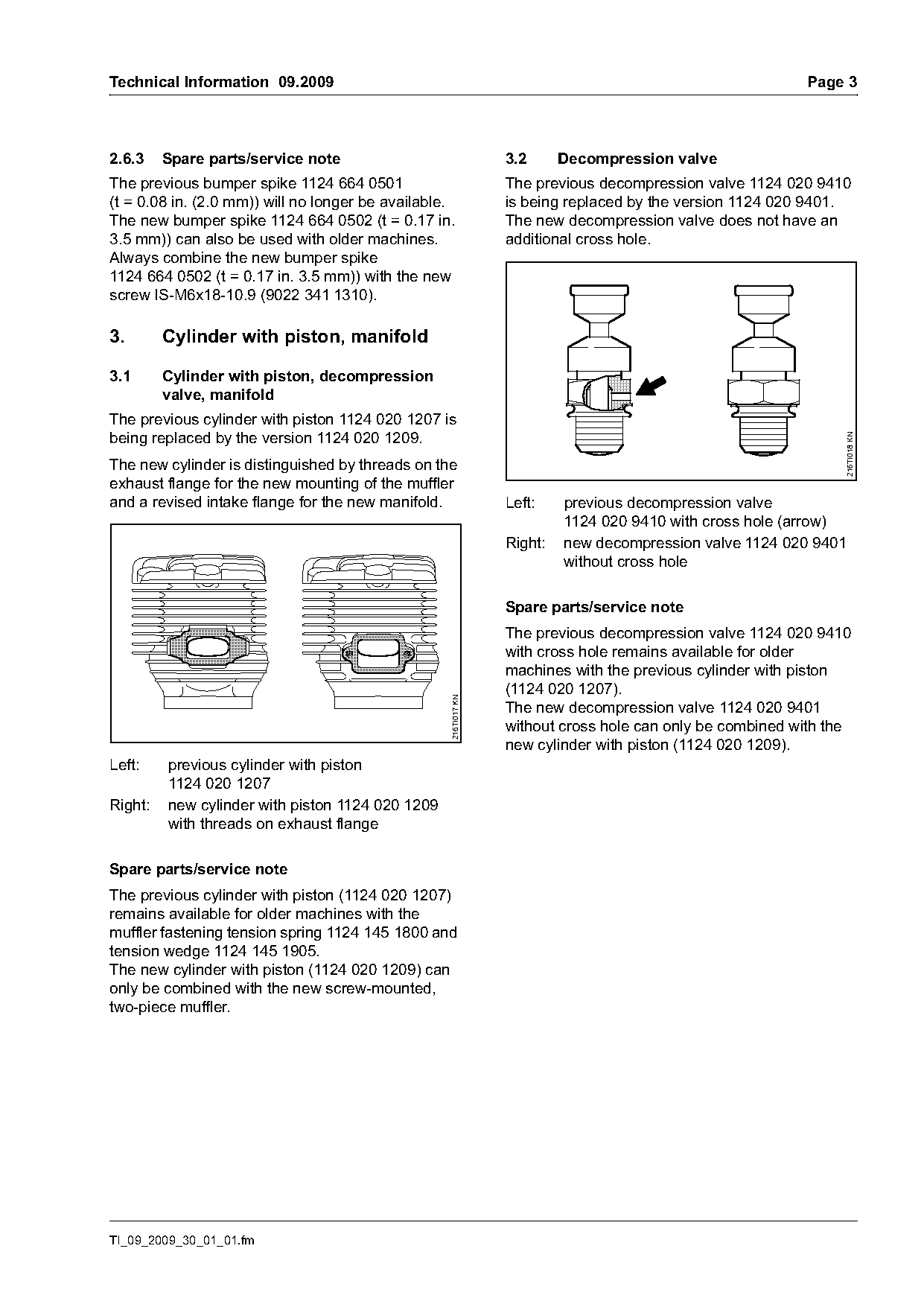
                                                                                                                216TI018 KN
The new cylinder is distinguished by threads on the
exhaust flange for the new mounting of the muffler
and a revised intake flange for the new manifold.                Left:    previous decompression valve
                                                                          1124 020 9410 with cross hole (arrow)
                                                                 Right:   new decompression valve 1124 020 9401
                                                                          without cross hole

                                                                 Spare parts/service note
                                                                 The previous decompression valve 1124 020 9410
                                                                 with cross hole remains available for older
                                                                 machines with the previous cylinder with piston
                                                                 (1124 020 1207).
                                                   216TI017 KN

                                                                 The new decompression valve 1124 020 9401
                                                                 without cross hole can only be combined with the
                                                                 new cylinder with piston (1124 020 1209).
Left:    previous cylinder with piston
         1124 020 1207
Right:   new cylinder with piston 1124 020 1209
         with threads on exhaust flange

Spare parts/service note
The previous cylinder with piston (1124 020 1207)
remains available for older machines with the
muffler fastening tension spring 1124 145 1800 and
tension wedge 1124 145 1905.
The new cylinder with piston (1124 020 1209) can
only be combined with the new screw-mounted,
two-piece muffler.

TI_09_2009_30_01_01.fm
Page 4 of 11
Text of page 4 — search, copy, screen readers
Page 4                                                                                 Technical Information 09.2009

3.3      Manifold                                               4.       Flywheel, ignition module,
The previous manifold 1124 141 2201 is being                             wiring harness, screw
replaced by the version 1124 141 2202.
                                                                4.1      Flywheel
                                                                The previous polymer/aluminum composite flywheel
                                                                1124 400 1210 is being replaced by an aluminum
                                                                version 1124 400 1201.

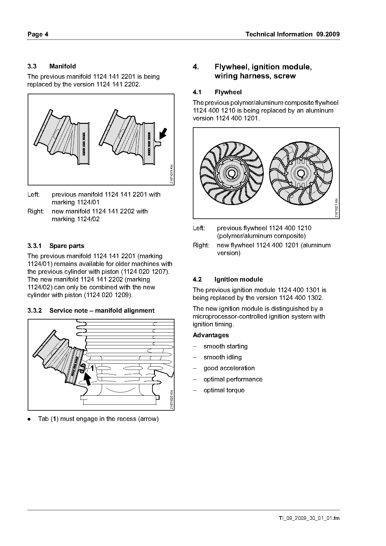
                                                  216TI019 KN

Left:     previous manifold 1124 141 2201 with

                                                                                                                     216TI021 KN
          marking 1124/01
Right:    new manifold 1124 141 2202 with
          marking 1124/02
                                                                Left:     previous flywheel 1124 400 1210
                                                                          (polymer/aluminum composite)
3.3.1    Spare parts                                            Right:    new flywheel 1124 400 1201 (aluminum
The previous manifold 1124 141 2201 (marking                              version)
1124/01) remains available for older machines with
the previous cylinder with piston (1124 020 1207).
The new manifold 1124 141 2202 (marking                         4.2      Ignition module
1124/02) can only be combined with the new                      The previous ignition module 1124 400 1301 is
cylinder with piston (1124 020 1209).                           being replaced by the version 1124 400 1302.
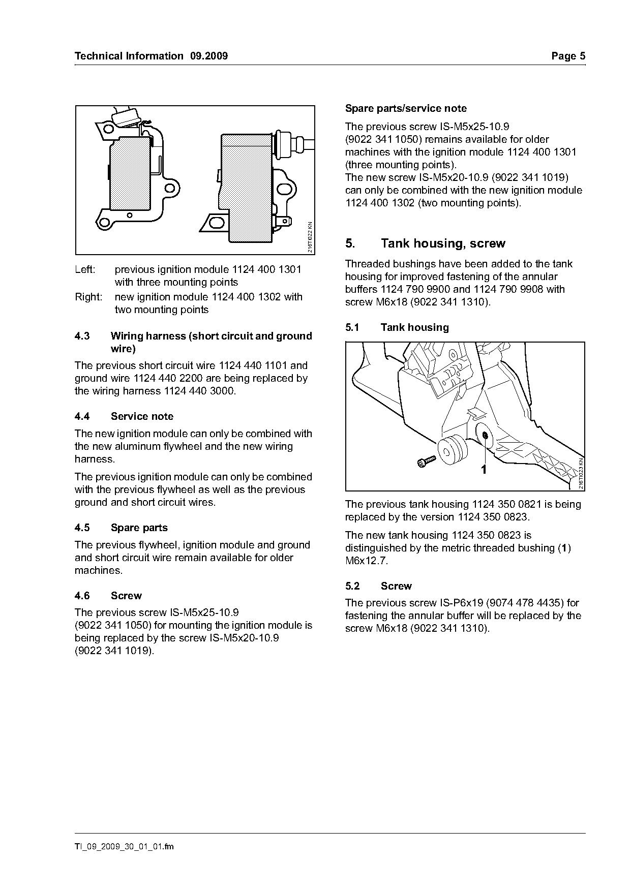
3.3.2    Service note – manifold alignment                      The new ignition module is distinguished by a
                                                                microprocessor-controlled ignition system with
                                                                ignition timing.
                                                                Advantages
                                                                –     smooth starting
                                                                –     smooth idling
                       1                                        –     good acceleration
                                                                –     optimal performance
                                                                –     optimal torque
                                                  216TI020 KN

.     Tab (1) must engage in the recess (arrow)

                                                                                                 TI_09_2009_30_01_01.fm
Page 5 of 11
Text of page 5 — search, copy, screen readers
Technical Information 09.2009                                                                                Page 5

                                                                Spare parts/service note
                                                                The previous screw IS-M5x25-10.9
                                                                (9022 341 1050) remains available for older
                                                                machines with the ignition module 1124 400 1301
                                                                (three mounting points).
                                                                The new screw IS-M5x20-10.9 (9022 341 1019)
                                                                can only be combined with the new ignition module
                                                                1124 400 1302 (two mounting points).

                                                  216TI022 KN
                                                                5.     Tank housing, screw
                                                                Threaded bushings have been added to the tank
Left:    previous ignition module 1124 400 1301
                                                                housing for improved fastening of the annular
         with three mounting points
                                                                buffers 1124 790 9900 and 1124 790 9908 with
Right:   new ignition module 1124 400 1302 with                 screw M6x18 (9022 341 1310).
         two mounting points
                                                                5.1    Tank housing
4.3      Wiring harness (short circuit and ground
         wire)
The previous short circuit wire 1124 440 1101 and
ground wire 1124 440 2200 are being replaced by
the wiring harness 1124 440 3000.

4.4      Service note
The new ignition module can only be combined with
the new aluminum flywheel and the new wiring
harness.

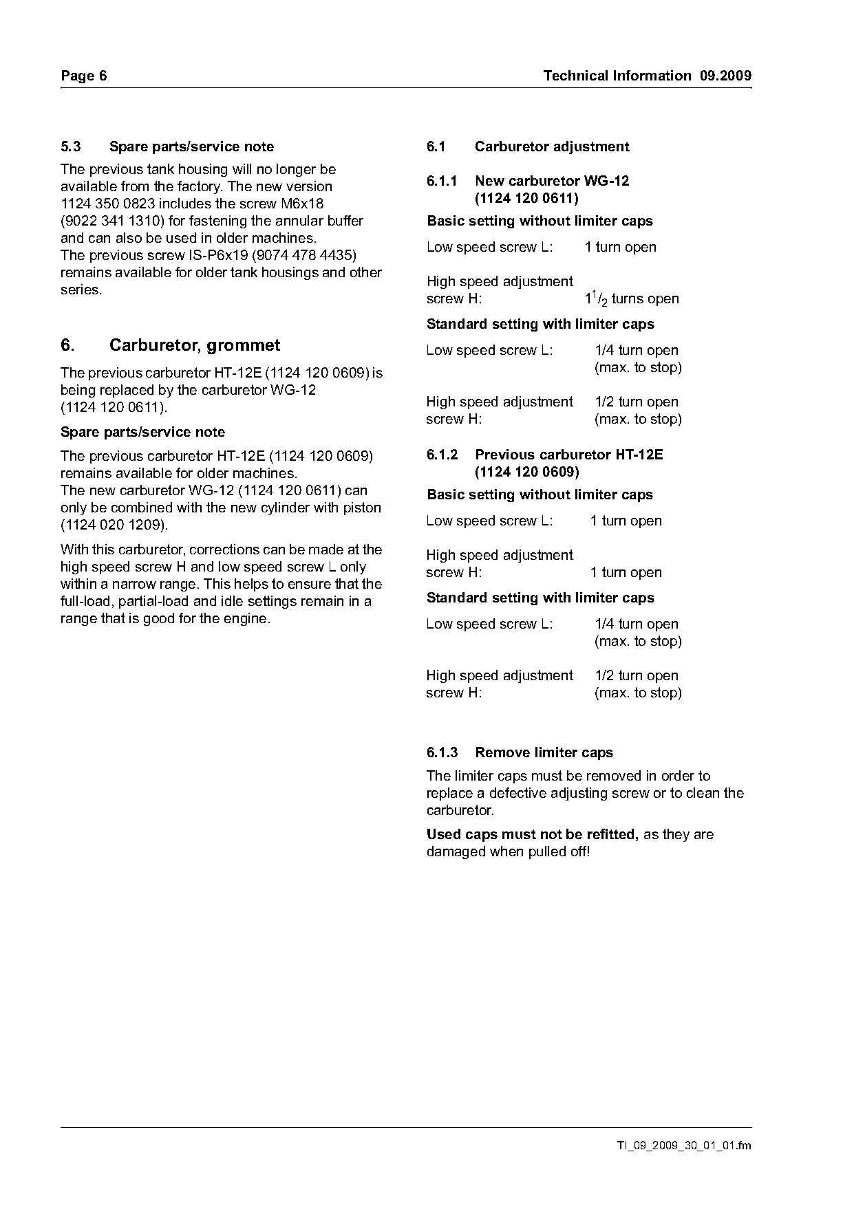
                                                                                                                   216TI023 KN
                                                                                             1
The previous ignition module can only be combined
with the previous flywheel as well as the previous
ground and short circuit wires.                                 The previous tank housing 1124 350 0821 is being
                                                                replaced by the version 1124 350 0823.
4.5      Spare parts
                                                                The new tank housing 1124 350 0823 is
The previous flywheel, ignition module and ground               distinguished by the metric threaded bushing (1)
and short circuit wire remain available for older               M6x12.7.
machines.
                                                                5.2    Screw
4.6      Screw
                                                                The previous screw IS-P6x19 (9074 478 4435) for
The previous screw IS-M5x25-10.9                                fastening the annular buffer will be replaced by the
(9022 341 1050) for mounting the ignition module is             screw M6x18 (9022 341 1310).
being replaced by the screw IS-M5x20-10.9
(9022 341 1019).

TI_09_2009_30_01_01.fm
Page 6 of 11
Text of page 6 — search, copy, screen readers
Page 6                                                                    Technical Information 09.2009

5.3      Spare parts/service note                       6.1     Carburetor adjustment
The previous tank housing will no longer be
available from the factory. The new version             6.1.1   New carburetor WG-12
1124 350 0823 includes the screw M6x18                          (1124 120 0611)
(9022 341 1310) for fastening the annular buffer        Basic setting without limiter caps
and can also be used in older machines.
                                                        Low speed screw L:       1 turn open
The previous screw IS-P6x19 (9074 478 4435)
remains available for older tank housings and other
                                                        High speed adjustment
series.
                                                        screw H:              11/2 turns open
                                                        Standard setting with limiter caps
6.       Carburetor, grommet                            Low speed screw L:        1/4 turn open
The previous carburetor HT-12E (1124 120 0609) is                                 (max. to stop)
being replaced by the carburetor WG-12
(1124 120 0611).                                        High speed adjustment     1/2 turn open
                                                        screw H:                  (max. to stop)
Spare parts/service note
The previous carburetor HT-12E (1124 120 0609)          6.1.2   Previous carburetor HT-12E
remains available for older machines.                           (1124 120 0609)
The new carburetor WG-12 (1124 120 0611) can            Basic setting without limiter caps
only be combined with the new cylinder with piston
(1124 020 1209).                                        Low speed screw L:        1 turn open

With this carburetor, corrections can be made at the    High speed adjustment
high speed screw H and low speed screw L only           screw H:                  1 turn open
within a narrow range. This helps to ensure that the
full-load, partial-load and idle settings remain in a   Standard setting with limiter caps
range that is good for the engine.                      Low speed screw L:        1/4 turn open
                                                                                  (max. to stop)

                                                        High speed adjustment     1/2 turn open
                                                        screw H:                  (max. to stop)

                                                        6.1.3   Remove limiter caps
                                                        The limiter caps must be removed in order to
                                                        replace a defective adjusting screw or to clean the
                                                        carburetor.
                                                        Used caps must not be refitted, as they are
                                                        damaged when pulled off!

                                                                                      TI_09_2009_30_01_01.fm
Page 7 of 11
Text of page 7 — search, copy, screen readers
Technical Information 09.2009                                                                                         Page 7

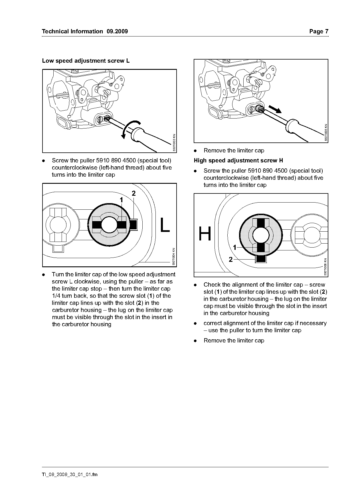
Low speed adjustment screw L

                                                                                                                             550TI005 KN
                                                      550TI003 KN
                                                                    .   Remove the limiter cap
.   Screw the puller 5910 890 4500 (special tool)                   High speed adjustment screw H
    counterclockwise (left-hand thread) about five
                                                                    .   Screw the puller 5910 890 4500 (special tool)
    turns into the limiter cap
                                                                        counterclockwise (left-hand thread) about five
                                                                        turns into the limiter cap
                                   2
                              1

                                              L                         H           1
                                                     550TI004 KN


                                                                                                                            550TI006 KN
.   Turn the limiter cap of the low speed adjustment
    screw L clockwise, using the puller – as far as
                                                                    .   Check the alignment of the limiter cap – screw
    the limiter cap stop – then turn the limiter cap
                                                                        slot (1) of the limiter cap lines up with the slot (2)
    1/4 turn back, so that the screw slot (1) of the
                                                                        in the carburetor housing – the lug on the limiter
    limiter cap lines up with the slot (2) in the
                                                                        cap must be visible through the slot in the insert
    carburetor housing – the lug on the limiter cap
                                                                        in the carburetor housing
    must be visible through the slot in the insert in
    the carburetor housing                                          .   correct alignment of the limiter cap if necessary
                                                                        – use the puller to turn the limiter cap
                                                                    .   Remove the limiter cap

TI_09_2009_30_01_01.fm
Page 8 of 11
Text of page 8 — search, copy, screen readers
Page 8                                                                                     Technical Information 09.2009

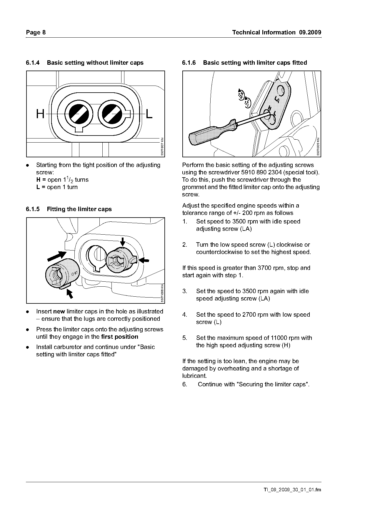
6.1.4    Basic setting without limiter caps                           6.1.6     Basic setting with limiter caps fitted

    H                                          L

                                                    550TI007 KN

                                                                                                                           550TI009 KN
.   Starting from the tight position of the adjusting                 Perform the basic setting of the adjusting screws
    screw:                                                            using the screwdriver 5910 890 2304 (special tool).
    H = open 11/2 turns                                               To do this, push the screwdriver through the
    L = open 1 turn                                                   grommet and the fitted limiter cap onto the adjusting
                                                                      screw.
                                                                      Adjust the specified engine speeds within a
6.1.5    Fitting the limiter caps
                                                                      tolerance range of +/- 200 rpm as follows
                                                                      1. Set speed to 3500 rpm with idle speed
                                                                            adjusting screw (LA)

                                                                      2.      Turn the low speed screw (L) clockwise or
                                                                              counterclockwise to set the highest speed.

                                                                      If this speed is greater than 3700 rpm, stop and
                                                                      start again with step 1.
                                                        550TI008 KN

                                                                      3.      Set the speed to 3500 rpm again with idle
                                                                              speed adjusting screw (LA)

.   Insert new limiter caps in the hole as illustrated
                                                                      4.      Set the speed to 2700 rpm with low speed
    – ensure that the lugs are correctly positioned
                                                                              screw (L)
.   Press the limiter caps onto the adjusting screws
    until they engage in the first position                           5.      Set the maximum speed of 11000 rpm with
.   Install carburetor and continue under "Basic                              the high speed adjusting screw (H)
    setting with limiter caps fitted"
                                                                      If the setting is too lean, the engine may be
                                                                      damaged by overheating and a shortage of
                                                                      lubricant.
                                                                      6.     Continue with "Securing the limiter caps".

                                                                                                      TI_09_2009_30_01_01.fm
Page 9 of 11
Text of page 9 — search, copy, screen readers
Technical Information 09.2009                                                                                     Page 9

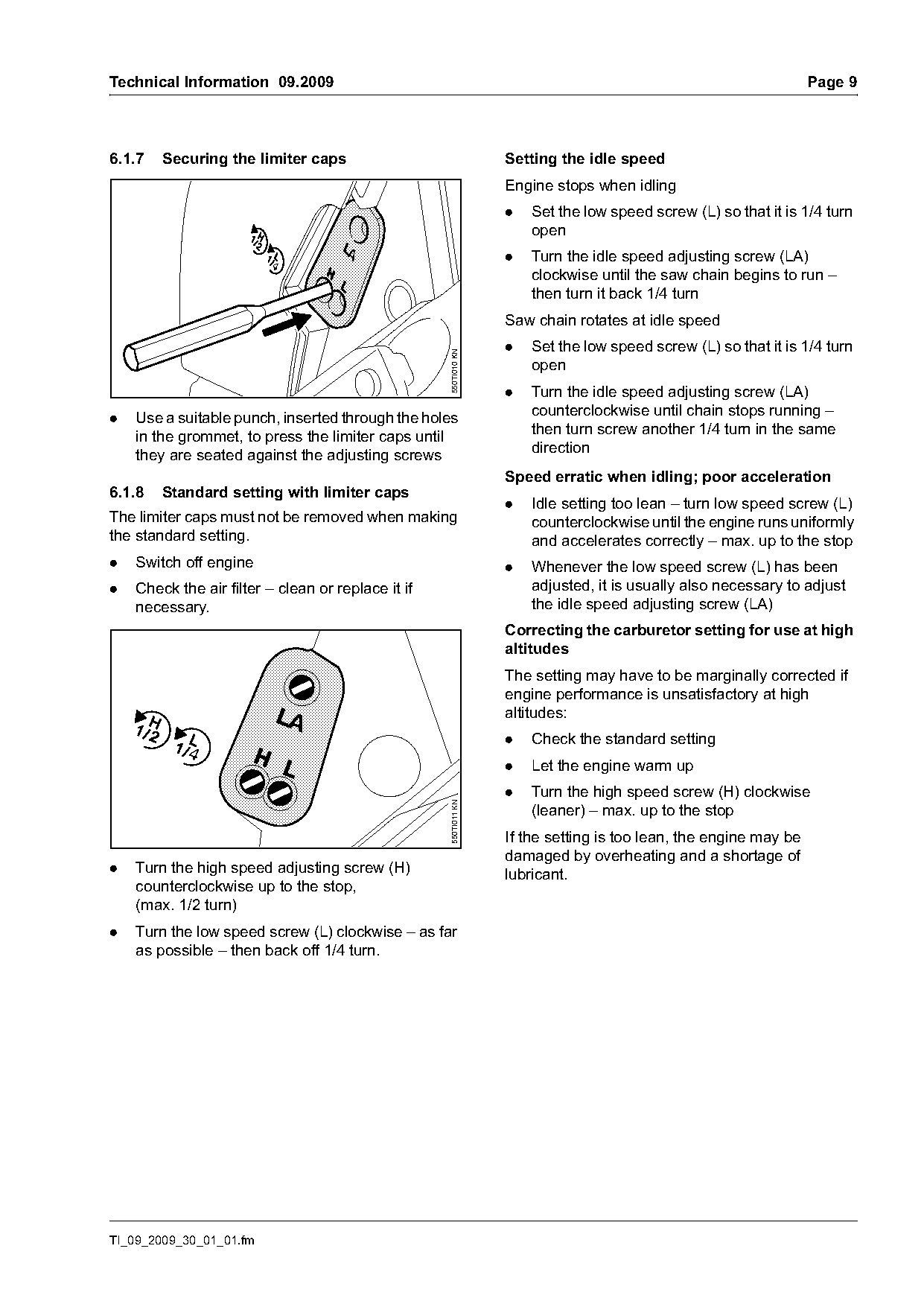
6.1.7   Securing the limiter caps                                 Setting the idle speed
                                                                  Engine stops when idling
                                                                  .   Set the low speed screw (L) so that it is 1/4 turn
                                                                      open
                                                                  .   Turn the idle speed adjusting screw (LA)
                                                                      clockwise until the saw chain begins to run –
                                                                      then turn it back 1/4 turn
                                                                  Saw chain rotates at idle speed
                                                                  .   Set the low speed screw (L) so that it is 1/4 turn

                                                    550TI010 KN
                                                                      open
                                                                  .   Turn the idle speed adjusting screw (LA)
                                                                      counterclockwise until chain stops running –
.   Use a suitable punch, inserted through the holes
                                                                      then turn screw another 1/4 turn in the same
    in the grommet, to press the limiter caps until
                                                                      direction
    they are seated against the adjusting screws
                                                                  Speed erratic when idling; poor acceleration
6.1.8   Standard setting with limiter caps
                                                                  .   Idle setting too lean – turn low speed screw (L)
The limiter caps must not be removed when making                      counterclockwise until the engine runs uniformly
the standard setting.                                                 and accelerates correctly – max. up to the stop
.   Switch off engine                                             .   Whenever the low speed screw (L) has been
.   Check the air filter – clean or replace it if                     adjusted, it is usually also necessary to adjust
    necessary.                                                        the idle speed adjusting screw (LA)
                                                                  Correcting the carburetor setting for use at high
                                                                  altitudes
                                                                  The setting may have to be marginally corrected if
                                                                  engine performance is unsatisfactory at high
                                                                  altitudes:
                                                                  .   Check the standard setting
                                                                  .   Let the engine warm up
                                                                  .   Turn the high speed screw (H) clockwise
                                                    550TI011 KN

                                                                      (leaner) – max. up to the stop
                                                                  If the setting is too lean, the engine may be
                                                                  damaged by overheating and a shortage of
.   Turn the high speed adjusting screw (H)                       lubricant.
    counterclockwise up to the stop,
    (max. 1/2 turn)
.   Turn the low speed screw (L) clockwise – as far
    as possible – then back off 1/4 turn.

TI_09_2009_30_01_01.fm
Page 10 of 11
Text of page 10 — search, copy, screen readers
Page 10                                                                              Technical Information 09.2009

6.2      Grommet                                                  The new double lever consists of throttle rod and
The previous grommet 1124 123 7501 is being                       double lever and is distinguished by a throttle rod
replaced by the version 1124 123 7502.                            that has been extended on the end toward the
                                                                  double lever.
                                                                  Spare parts/service note
                                                                  The previous individual parts will no longer be
                                                                  available from the factory. The new double lever
                                                                  1124 180 4050 can also be used with older
                                                                  machines.

                                                    216TI024 KN

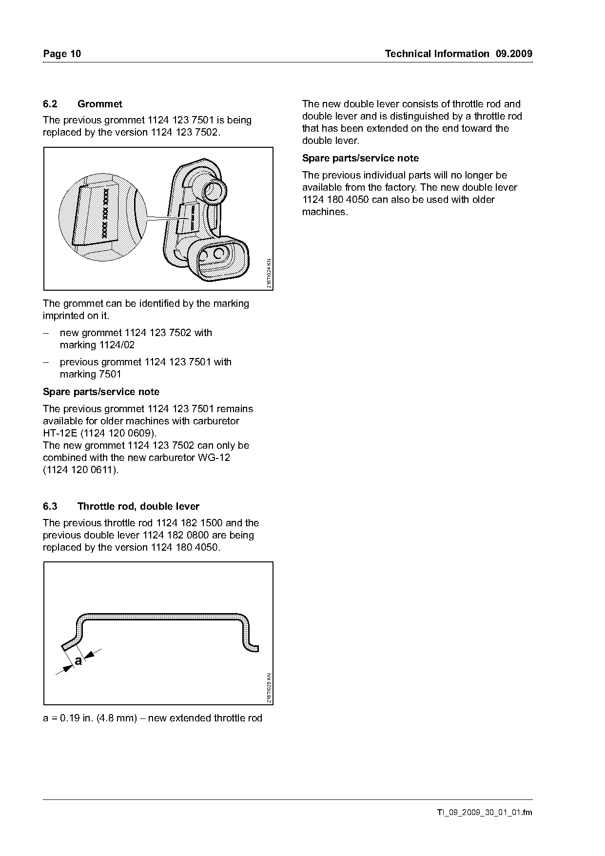
The grommet can be identified by the marking
imprinted on it.
–     new grommet 1124 123 7502 with
      marking 1124/02
–     previous grommet 1124 123 7501 with
      marking 7501
Spare parts/service note
The previous grommet 1124 123 7501 remains
available for older machines with carburetor
HT-12E (1124 120 0609).
The new grommet 1124 123 7502 can only be
combined with the new carburetor WG-12
(1124 120 0611).

6.3      Throttle rod, double lever
The previous throttle rod 1124 182 1500 and the
previous double lever 1124 182 0800 are being
replaced by the version 1124 180 4050.

        a
                                                    216TI025 KN

a = 0.19 in. (4.8 mm) – new extended throttle rod

                                                                                                 TI_09_2009_30_01_01.fm
Page 11 of 11
Text of page 11 — search, copy, screen readers
Technical Information 09.2009                                                                         Page 11

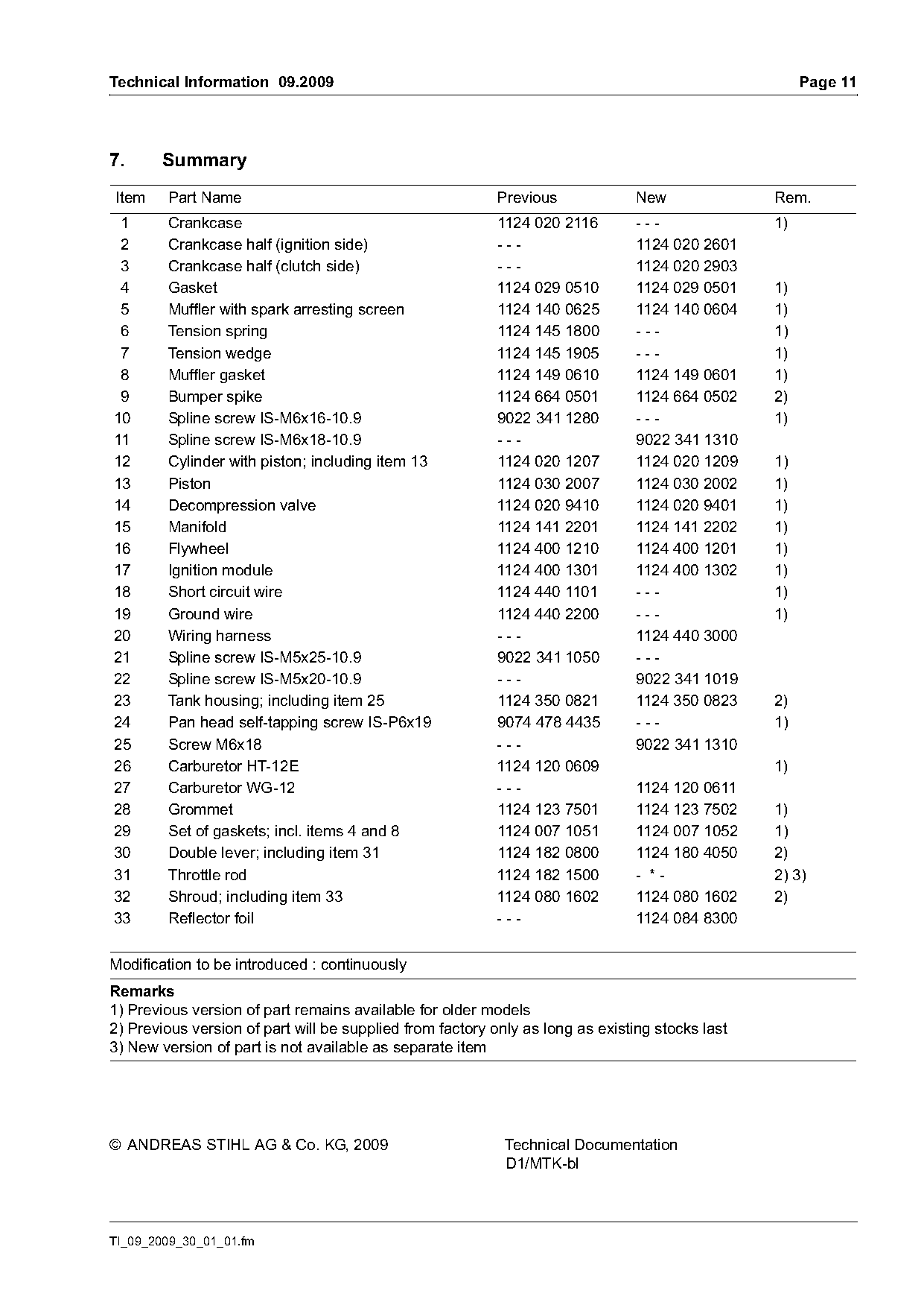
7.      Summary
Item    Part Name                                         Previous              New              Rem.
 1      Crankcase                                         1124 020 2116         ---              1)
 2      Crankcase half (ignition side)                    ---                   1124 020 2601
 3      Crankcase half (clutch side)                      ---                   1124 020 2903
 4      Gasket                                            1124 029 0510         1124 029 0501    1)
 5      Muffler with spark arresting screen               1124 140 0625         1124 140 0604    1)
 6      Tension spring                                    1124 145 1800         ---              1)
 7      Tension wedge                                     1124 145 1905         ---              1)
 8      Muffler gasket                                    1124 149 0610         1124 149 0601    1)
 9      Bumper spike                                      1124 664 0501         1124 664 0502    2)
10      Spline screw IS-M6x16-10.9                        9022 341 1280         ---              1)
11      Spline screw IS-M6x18-10.9                        ---                   9022 341 1310
12      Cylinder with piston; including item 13           1124 020 1207         1124 020 1209    1)
13      Piston                                            1124 030 2007         1124 030 2002    1)
14      Decompression valve                               1124 020 9410         1124 020 9401    1)
15      Manifold                                          1124 141 2201         1124 141 2202    1)
16      Flywheel                                          1124 400 1210         1124 400 1201    1)
17      Ignition module                                   1124 400 1301         1124 400 1302    1)
18      Short circuit wire                                1124 440 1101         ---              1)
19      Ground wire                                       1124 440 2200         ---              1)
20      Wiring harness                                    ---                   1124 440 3000
21      Spline screw IS-M5x25-10.9                        9022 341 1050         ---
22      Spline screw IS-M5x20-10.9                        ---                   9022 341 1019
23      Tank housing; including item 25                   1124 350 0821         1124 350 0823    2)
24      Pan head self-tapping screw IS-P6x19              9074 478 4435         ---              1)
25      Screw M6x18                                       ---                   9022 341 1310
26      Carburetor HT-12E                                 1124 120 0609                          1)
27      Carburetor WG-12                                  ---                   1124 120 0611
28      Grommet                                           1124 123 7501         1124 123 7502    1)
29      Set of gaskets; incl. items 4 and 8               1124 007 1051         1124 007 1052    1)
30      Double lever; including item 31                   1124 182 0800         1124 180 4050    2)
31      Throttle rod                                      1124 182 1500         - *-             2) 3)
32      Shroud; including item 33                         1124 080 1602         1124 080 1602    2)
33      Reflector foil                                    ---                   1124 084 8300

Modification to be introduced : continuously
Remarks
1) Previous version of part remains available for older models
2) Previous version of part will be supplied from factory only as long as existing stocks last
3) New version of part is not available as separate item

© ANDREAS STIHL AG & Co. KG, 2009                           Technical Documentation
                                                            D1/MTK-bl

TI_09_2009_30_01_01.fm
Most of these PDFs embed fonts with a shifted character map, so the text above was recovered rather than copied — read it as a faithful but imperfect transcription, and treat the page image above each block as the authority where the two disagree — the figures exist only there, because they are vector drawings that text extraction cannot keep.