Technical Information · issue 11 of 2009
New STIHL SR 430, SR 450 Sprayers
IssueTI 11/2009
Full text
Page 1 of 13
Text of page 1 — search, copy, screen readers
STIH)

Technical Information                          11.2009

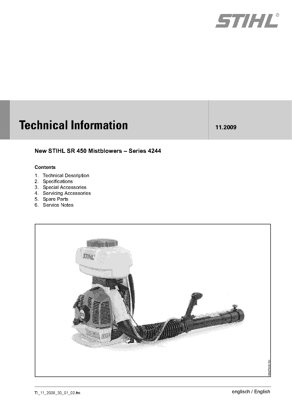
  New STIHL SR 450 Mistblowers – Series 4244

  Contents
  1.   Technical Description
  2.   Specifications
  3.   Special Accessories
  4.   Servicing Accessories
  5.   Spare Parts
  6.   Service Notes

  TI_11_2009_30_01_02.fm                            englisch / English
Page 2 of 13
Text of page 2 — search, copy, screen readers
Page 2                                                                     Technical Information 11.2009

The STIHL SR 450 backpack mistblower is the new,       1.        Technical Description
pacesetting replacement to the STIHL SR 420.
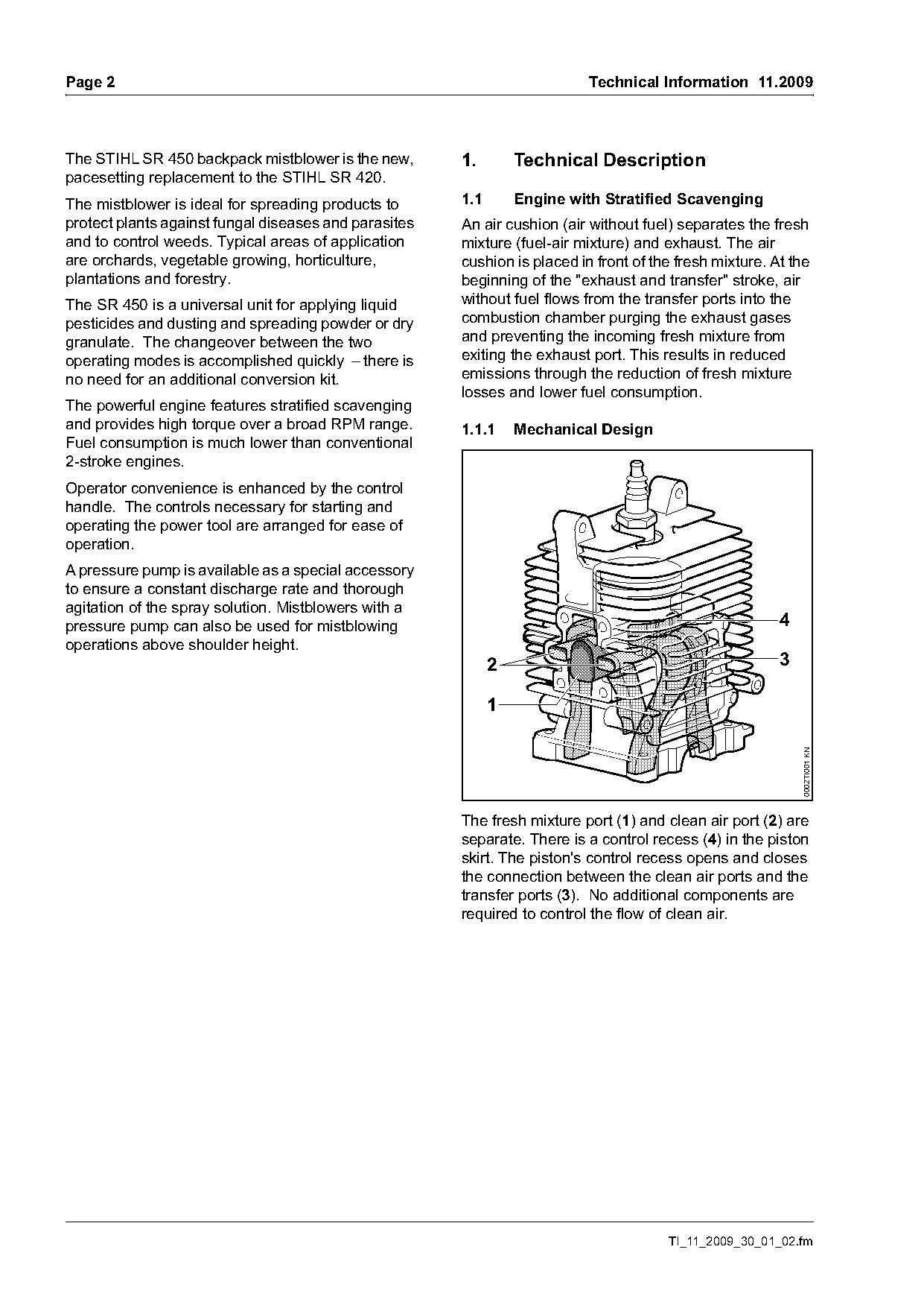
The mistblower is ideal for spreading products to      1.1       Engine with Stratified Scavenging
protect plants against fungal diseases and parasites   An air cushion (air without fuel) separates the fresh
and to control weeds. Typical areas of application     mixture (fuel-air mixture) and exhaust. The air
are orchards, vegetable growing, horticulture,         cushion is placed in front of the fresh mixture. At the
plantations and forestry.                              beginning of the "exhaust and transfer" stroke, air
The SR 450 is a universal unit for applying liquid     without fuel flows from the transfer ports into the
pesticides and dusting and spreading powder or dry     combustion chamber purging the exhaust gases
granulate. The changeover between the two              and preventing the incoming fresh mixture from
operating modes is accomplished quickly – there is     exiting the exhaust port. This results in reduced
no need for an additional conversion kit.              emissions through the reduction of fresh mixture
                                                       losses and lower fuel consumption.
The powerful engine features stratified scavenging
and provides high torque over a broad RPM range.       1.1.1     Mechanical Design
Fuel consumption is much lower than conventional
2-stroke engines.
Operator convenience is enhanced by the control
handle. The controls necessary for starting and
operating the power tool are arranged for ease of
operation.
A pressure pump is available as a special accessory
to ensure a constant discharge rate and thorough
agitation of the spray solution. Mistblowers with a
pressure pump can also be used for mistblowing                                                           4
operations above shoulder height.
                                                             2                                           3


                                                                                                             0002TI001 KN

                                                       The fresh mixture port (1) and clean air port (2) are
                                                       separate. There is a control recess (4) in the piston
                                                       skirt. The piston's control recess opens and closes
                                                       the connection between the clean air ports and the
                                                       transfer ports (3). No additional components are
                                                       required to control the flow of clean air.

                                                                                       TI_11_2009_30_01_02.fm
Page 3 of 13
Text of page 3 — search, copy, screen readers
Technical Information 11.2009                                                                                    Page 3

1.2       Control Handle                                              1.2.2   Levers
                                                                      Valve lever

                          1                                                                     a

                                                                                                        b
                                            3
                  2

                                                       0002TI002 KN

                                                                                                                          0002TI004 KN
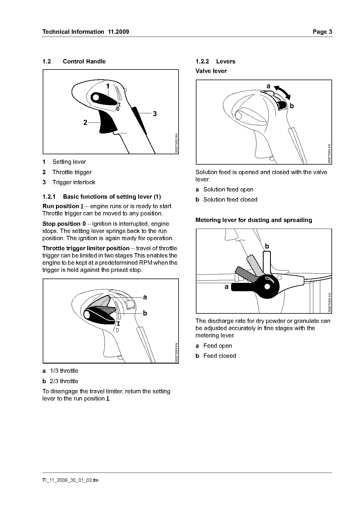
1     Setting lever
2     Throttle trigger                                                Solution feed is opened and closed with the valve
3     Trigger interlock                                               lever.
                                                                      a Solution feed open
1.2.1     Basic functions of setting lever (1)
                                                                      b Solution feed closed
Run position F – engine runs or is ready to start
Throttle trigger can be moved to any position.
                                                                      Metering lever for dusting and spreading
Stop position 0 – ignition is interrupted, engine
stops. The setting lever springs back to the run
position. The ignition is again ready for operation.
Throttle trigger limiter position – travel of throttle                                         b
trigger can be limited in two stages This enables the
engine to be kept at a predetermined RPM when the
trigger is held against the preset stop.

                                                                                a
                                        a

                                                                                                                          0002TI005 KN
                                        b
                                                                      The discharge rate for dry powder or granulate can
                                                                      be adjusted accurately in fine stages with the
                                                                      metering lever.
                                                                      a Feed open
                                                       0002TI003 KN

                                                                      b Feed closed

a 1/3 throttle
b 2/3 throttle
To disengage the travel limiter, return the setting
lever to the run position F.

TI_11_2009_30_01_02.fm
Page 4 of 13
Text of page 4 — search, copy, screen readers
Page 4                                                                                     Technical Information 11.2009

1.3       Metering Knob for Mistblowing                             1.4        Conversion from Mistblowing Mode to
                                                                               Dusting and Spreading Mode
                                                                    The conversion involves turning the solution tank
                    1                                               180° and removing the nozzle from the blower tube.

                                                                    1.4.1      Solution tank

      2                                                                 A

                                                     0002TI006 KN

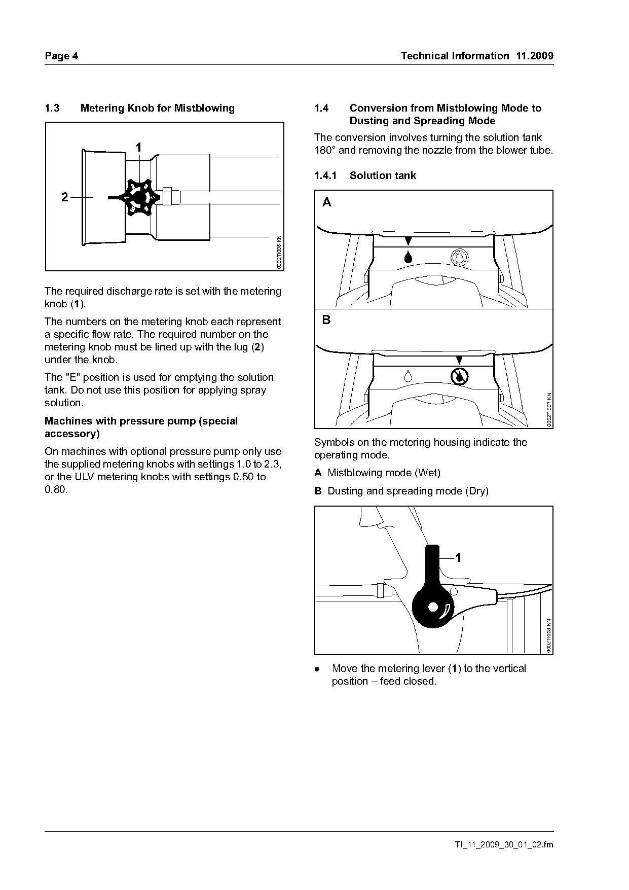
The required discharge rate is set with the metering
knob (1).
The numbers on the metering knob each represent                         B
a specific flow rate. The required number on the
metering knob must be lined up with the lug (2)
under the knob.
The "E" position is used for emptying the solution
tank. Do not use this position for applying spray

                                                                                                                           0002TI007 KN
solution.
Machines with pressure pump (special
accessory)
                                                                    Symbols on the metering housing indicate the
On machines with optional pressure pump only use                    operating mode.
the supplied metering knobs with settings 1.0 to 2.3,
or the ULV metering knobs with settings 0.50 to                     A Mistblowing mode (Wet)
0.80.                                                               B Dusting and spreading mode (Dry)

                                                                                                       1
                                                                                                                           0002TI008 KN

                                                                    .       Move the metering lever (1) to the vertical
                                                                            position – feed closed.

                                                                                                       TI_11_2009_30_01_02.fm
Page 5 of 13
Text of page 5 — search, copy, screen readers
Technical Information 11.2009                                                                                           Page 5

                                                                                            3
                                                                                                                5


                                                                                                                                   0002TI012 KN
                                                     0002TI009 KN
                         2       2

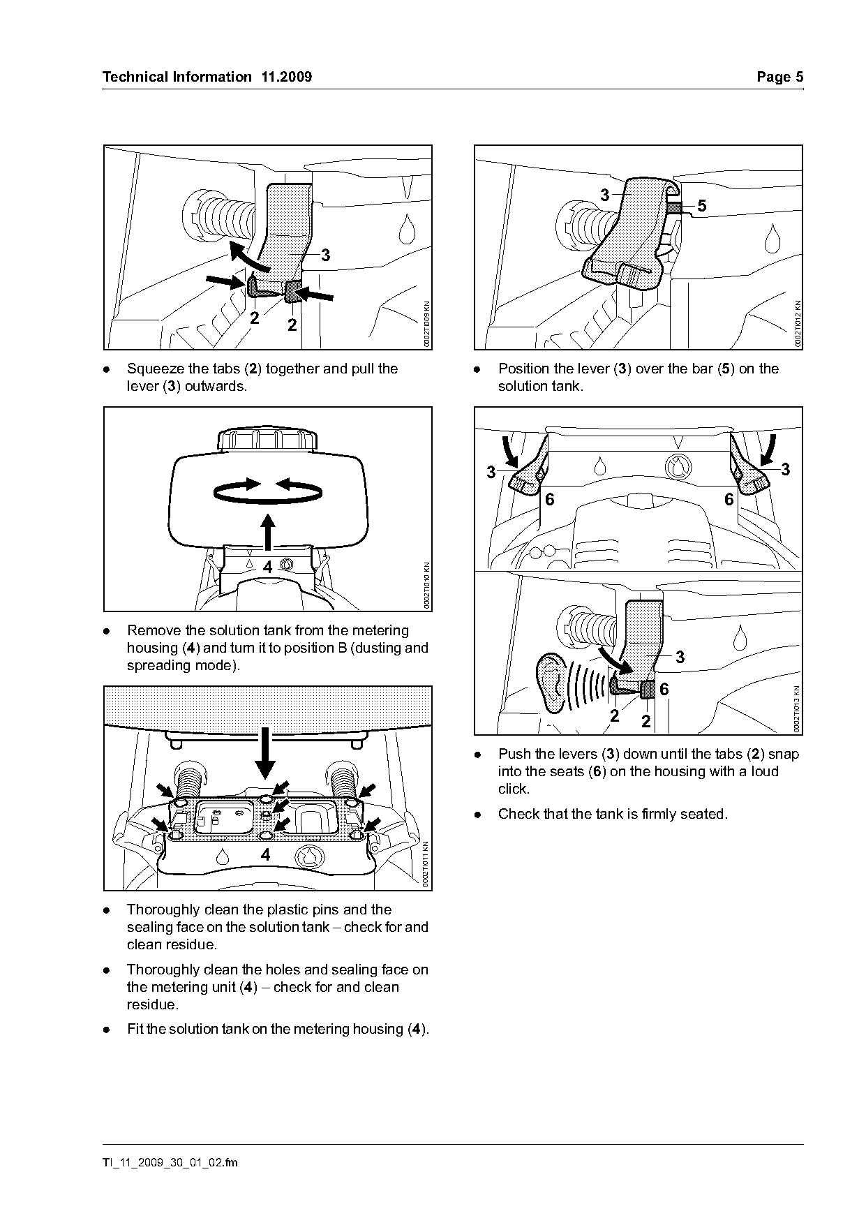
.   Squeeze the tabs (2) together and pull the                      .       Position the lever (3) over the bar (5) on the
    lever (3) outwards.                                                     solution tank.

                                                                        3                                                    3
                                                                                   6                                6

                             4
                                                     0002TI010 KN

.   Remove the solution tank from the metering
    housing (4) and turn it to position B (dusting and
    spreading mode).                                                                                        3
                                                                                                        6

                                                                                                                                 0002TI013 KN
                                                                                                2   2
                                                                    .       Push the levers (3) down until the tabs (2) snap
                                                                            into the seats (6) on the housing with a loud
                                                                            click.
                                                                    .       Check that the tank is firmly seated.
                                                    0002TI011 KN


.   Thoroughly clean the plastic pins and the
    sealing face on the solution tank – check for and
    clean residue.
.   Thoroughly clean the holes and sealing face on
    the metering unit (4) – check for and clean
    residue.
.   Fit the solution tank on the metering housing (4).

TI_11_2009_30_01_02.fm
Page 6 of 13
Text of page 6 — search, copy, screen readers
Page 6                                                                                 Technical Information 11.2009

1.4.2    Blower Tube                                               1.5     Antistatic System – Dusting and
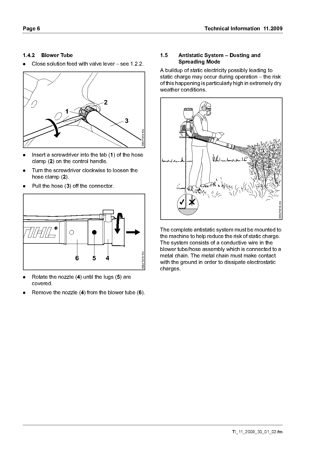
.   Close solution feed with valve lever – see 1.2.2.                      Spreading Mode
                                                                   A buildup of static electricity possibly leading to
                                                                   static charge may occur during operation – the risk
                                                                   of this happening is particularly high in extremely dry
                                                                   weather conditions.

                                   2
                  1
                                             3

                                                    0002TI014 KN

.   Insert a screwdriver into the tab (1) of the hose
    clamp (2) on the control handle.
.   Turn the screwdriver clockwise to loosen the
    hose clamp (2).
.   Pull the hose (3) off the connector.

                                                                                                                        0002TI016 KN
                                                                   The complete antistatic system must be mounted to
                                                                   the machine to help reduce the risk of static charge.
                                                                   The system consists of a conductive wire in the
                                                                   blower tube/hose assembly which is connected to a
                                                    0002TI015 KN

                       6            4                              metal chain. The metal chain must make contact
                              5
                                                                   with the ground in order to dissipate electrostatic
                                                                   charges.
.   Rotate the nozzle (4) until the lugs (5) are
    covered.
.   Remove the nozzle (4) from the blower tube (6).

                                                                                                   TI_11_2009_30_01_02.fm
Page 7 of 13
Text of page 7 — search, copy, screen readers
Technical Information 11.2009                                                                                      Page 7

1.5.1   Mounting the antistatic system
                                                                                              6

                             3
                                              1
                                                                                          8       4
                                         2

                                                       0002TI017 KN
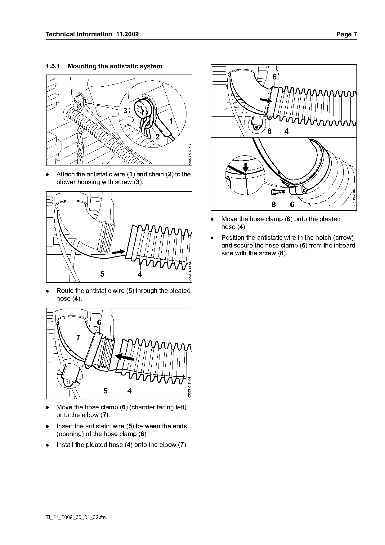
.   Attach the antistatic wire (1) and chain (2) to the
    blower housing with screw (3).

                                                                                                                         0002TI020 KN
                                                                                            8         6
                                                                      .   Move the hose clamp (6) onto the pleated
                                                                          hose (4).
                                                                      .   Position the antistatic wire in the notch (arrow)
                                                                          and secure the hose clamp (6) from the inboard
                                                                          side with the screw (8).
                                                       0002TI018 KN

                    5             4

.   Route the antistatic wire (5) through the pleated
    hose (4).

                   6
           7
                                                      0002TI019 KN

                       5      4

.   Move the hose clamp (6) (chamfer facing left)
    onto the elbow (7).
.   Insert the antistatic wire (5) between the ends
    (opening) of the hose clamp (6).
.   Install the pleated hose (4) onto the elbow (7).

TI_11_2009_30_01_02.fm
Page 8 of 13
Text of page 8 — search, copy, screen readers
Page 8                                                                           Technical Information 11.2009

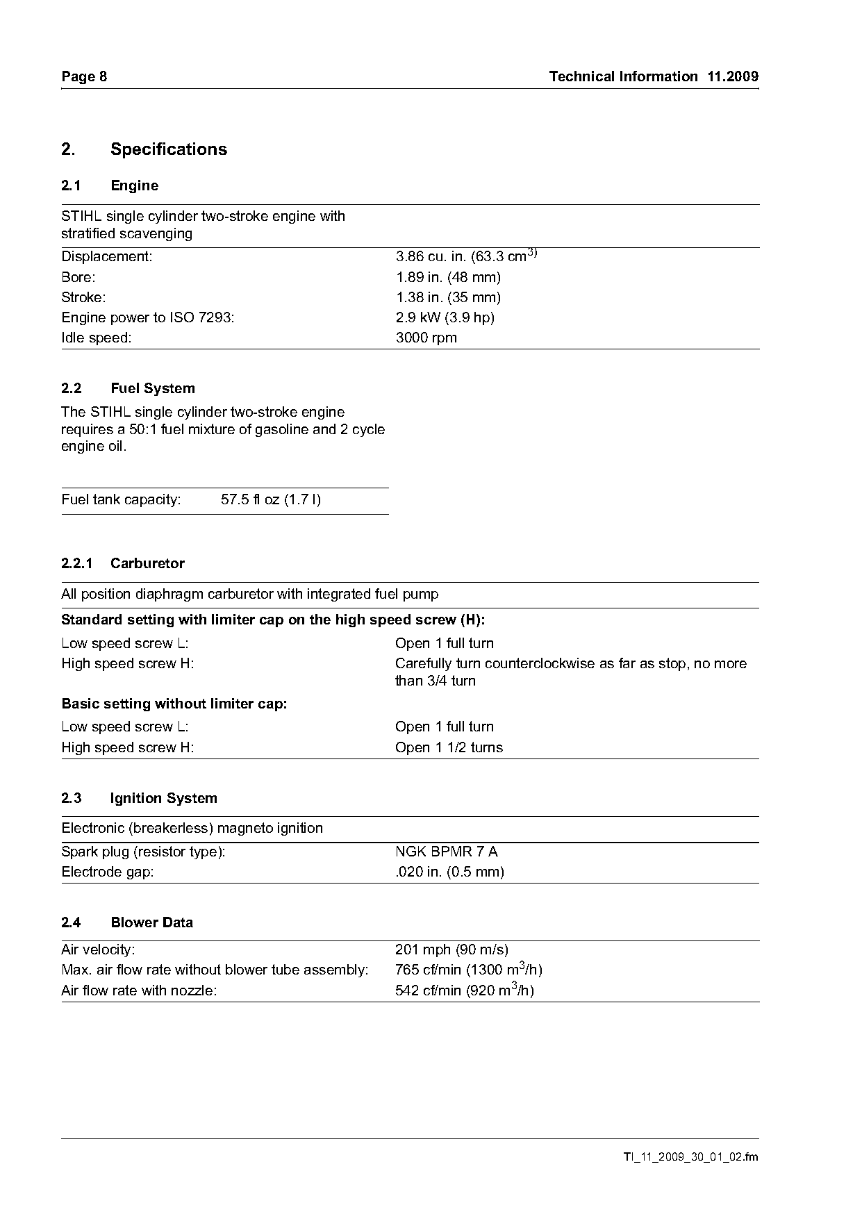
2.       Specifications

2.1      Engine

STIHL single cylinder two-stroke engine with
stratified scavenging
Displacement:                                          3.86 cu. in. (63.3 cm3)
Bore:                                                  1.89 in. (48 mm)
Stroke:                                                1.38 in. (35 mm)
Engine power to ISO 7293:                              2.9 kW (3.9 hp)
Idle speed:                                            3000 rpm

2.2      Fuel System
The STIHL single cylinder two-stroke engine
requires a 50:1 fuel mixture of gasoline and 2 cycle
engine oil.

Fuel tank capacity:        57.5 fl oz (1.7 l)

2.2.1    Carburetor

All position diaphragm carburetor with integrated fuel pump
Standard setting with limiter cap on the high speed screw (H):
Low speed screw L:                                     Open 1 full turn
High speed screw H:                                    Carefully turn counterclockwise as far as stop, no more
                                                       than 3/4 turn
Basic setting without limiter cap:
Low speed screw L:                                     Open 1 full turn
High speed screw H:                                    Open 1 1/2 turns

2.3      Ignition System

Electronic (breakerless) magneto ignition
Spark plug (resistor type):                            NGK BPMR 7 A
Electrode gap:                                         .020 in. (0.5 mm)

2.4      Blower Data
Air velocity:                                          201 mph (90 m/s)
Max. air flow rate without blower tube assembly:       765 cf/min (1300 m3/h)
Air flow rate with nozzle:                             542 cf/min (920 m3/h)

                                                                                           TI_11_2009_30_01_02.fm
Page 9 of 13
Text of page 9 — search, copy, screen readers
Technical Information 11.2009                                                                         Page 9

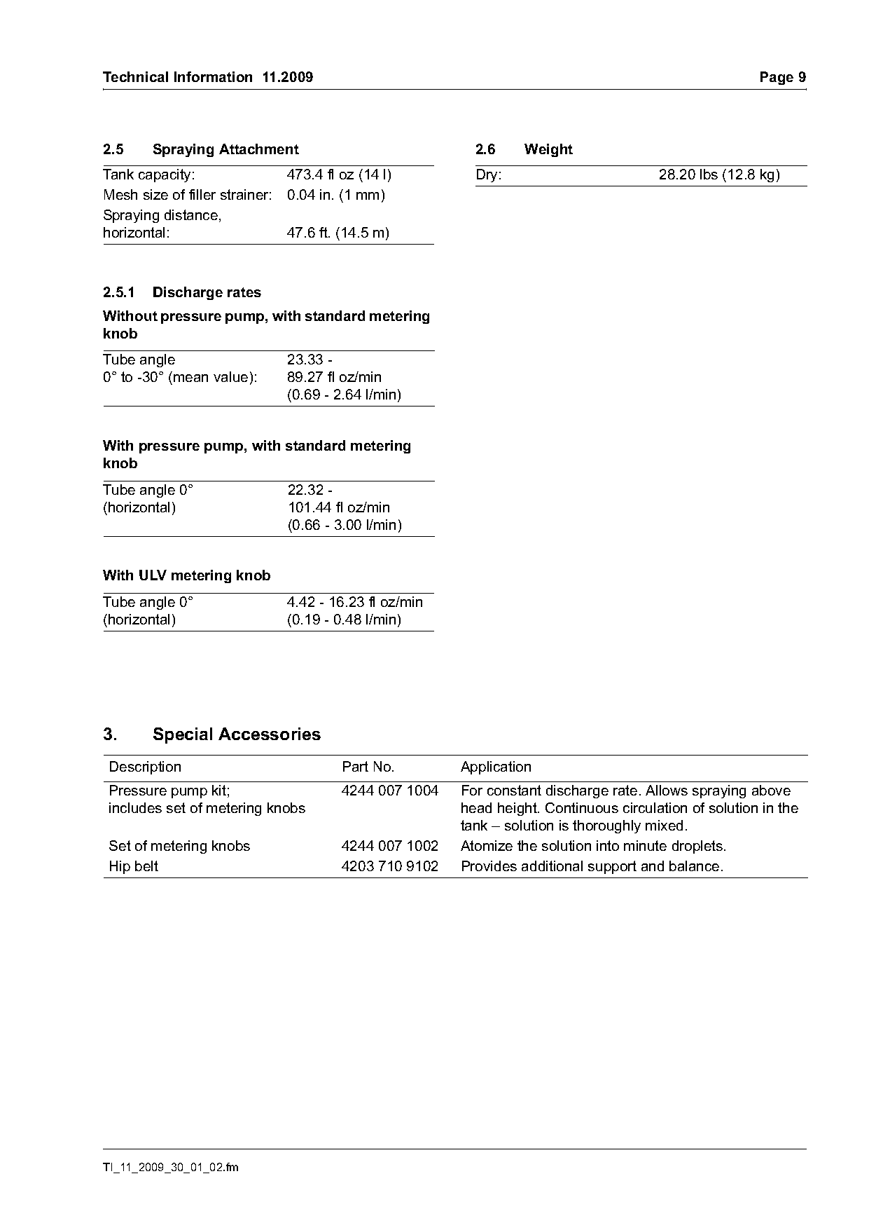
2.5     Spraying Attachment                              2.6     Weight
Tank capacity:                473.4 fl oz (14 l)         Dry:                         28.20 lbs (12.8 kg)
Mesh size of filler strainer: 0.04 in. (1 mm)
Spraying distance,
horizontal:                   47.6 ft. (14.5 m)

2.5.1   Discharge rates
Without pressure pump, with standard metering
knob
Tube angle                    23.33 -
0° to -30° (mean value):      89.27 fl oz/min
                              (0.69 - 2.64 l/min)

With pressure pump, with standard metering
knob
Tube angle 0°                 22.32 -
(horizontal)                  101.44 fl oz/min
                              (0.66 - 3.00 l/min)

With ULV metering knob
Tube angle 0°                 4.42 - 16.23 fl oz/min
(horizontal)                  (0.19 - 0.48 l/min)

3.      Special Accessories
Description                            Part No.        Application
Pressure pump kit;                     4244 007 1004   For constant discharge rate. Allows spraying above
includes set of metering knobs                         head height. Continuous circulation of solution in the
                                                       tank – solution is thoroughly mixed.
Set of metering knobs                  4244 007 1002   Atomize the solution into minute droplets.
Hip belt                               4203 710 9102   Provides additional support and balance.

TI_11_2009_30_01_02.fm
Page 10 of 13

Text of page 10 — search, copy, screen readers
Page 10                                                                                Technical Information 11.2009

4.     Servicing Accessories

4.1    Special servicing tools
The following new servicing tool is required for
models SR 450.

                                                   0002TI021 KN

Description                           Part No.                    Application
Clamping strap                        4244 893 2600               Compressing the piston rings

4.2    Servicing aids
Description                           Part No.                    Application
Carburetor parts kit                  4228 007 1051               C1Q-S 165 and C1Q-S 166 carburetors
Set of hooks                          4244 007 1008               Repairing the harness
Lubricating grease – 225 g tube       0781 120 1111               Oil seals, sliding and bearing points
STIHL press fluid OH 723              0781 957 9000               Rubber elements, fuel hoses
STIHL multipurpose grease             0781 120 1109               High voltage output on ignition module
Dirko HT red sealant                  0783 830 2000               Crankcase, oil seals (outside)
Standard commercial solvent-                                      Cleaning sealing faces and carburetor, crankshaft
based degreasant containing no                                    stubs and flywheel taper
chlorinated or halogenated
hydrocarbons

5.     Spare Parts
Dedicated parts documentation will be available for
the market launch of model SR 450.

                                                                                                   TI_11_2009_30_01_02.fm
Page 11 of 13
Text of page 11 — search, copy, screen readers
Technical Information 11.2009                                                                                        Page 11

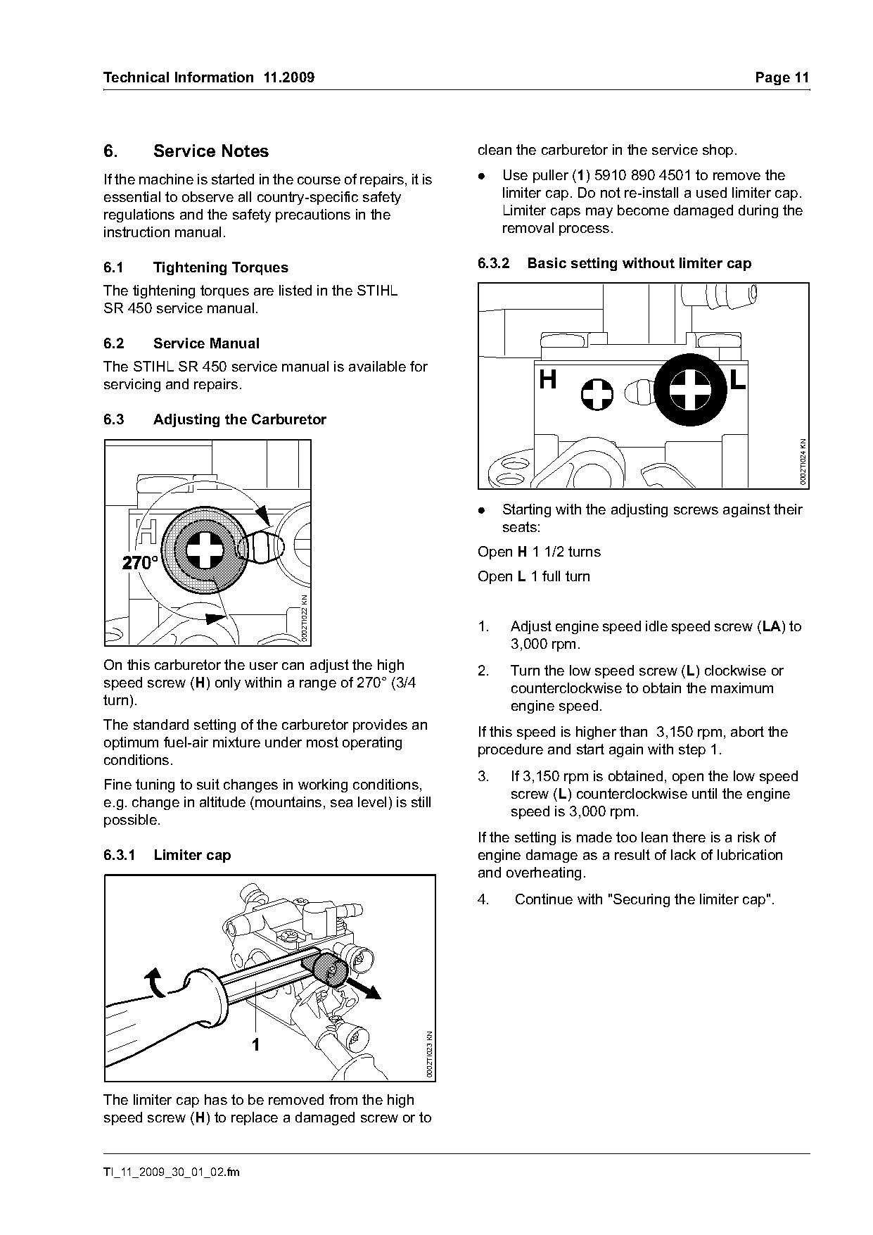
6.      Service Notes                                                 clean the carburetor in the service shop.

If the machine is started in the course of repairs, it is             .    Use puller (1) 5910 890 4501 to remove the
essential to observe all country-specific safety                           limiter cap. Do not re-install a used limiter cap.
regulations and the safety precautions in the                              Limiter caps may become damaged during the
instruction manual.                                                        removal process.

6.1     Tightening Torques                                            6.3.2     Basic setting without limiter cap
The tightening torques are listed in the STIHL
SR 450 service manual.

6.2     Service Manual
The STIHL SR 450 service manual is available for
servicing and repairs.                                                            H
6.3     Adjusting the Carburetor

                                                                                                                            0002TI024 KN
                                                                      .    Starting with the adjusting screws against their
                                                                           seats:
                                                                      Open H 1 1/2 turns
                                                                      Open L 1 full turn
                                  0002TI022 KN

                                                                      1.      Adjust engine speed idle speed screw (LA) to
                                                                              3,000 rpm.
On this carburetor the user can adjust the high                       2.      Turn the low speed screw (L) clockwise or
speed screw (H) only within a range of 270° (3/4                              counterclockwise to obtain the maximum
turn).                                                                        engine speed.
The standard setting of the carburetor provides an
                                                                      If this speed is higher than 3,150 rpm, abort the
optimum fuel-air mixture under most operating
                                                                      procedure and start again with step 1.
conditions.
                                                                      3.      If 3,150 rpm is obtained, open the low speed
Fine tuning to suit changes in working conditions,
                                                                              screw (L) counterclockwise until the engine
e.g. change in altitude (mountains, sea level) is still
                                                                              speed is 3,000 rpm.
possible.
                                                                      If the setting is made too lean there is a risk of
6.3.1   Limiter cap                                                   engine damage as a result of lack of lubrication
                                                                      and overheating.
                                                                      4.      Continue with "Securing the limiter cap".
                                                       0002TI023 KN


The limiter cap has to be removed from the high
speed screw (H) to replace a damaged screw or to

TI_11_2009_30_01_02.fm
Page 12 of 13
Text of page 12 — search, copy, screen readers
Page 12                                                                              Technical Information 11.2009

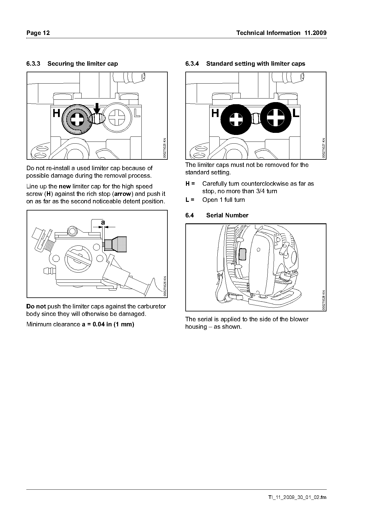
6.3.3   Securing the limiter cap                                 6.3.4    Standard setting with limiter caps

          H                                                                 H

                                                  0002TI025 KN

                                                                                                                     0002TI027 KN
                                                                 The limiter caps must not be removed for the
Do not re-install a used limiter cap because of
                                                                 standard setting.
possible damage during the removal process.
Line up the new limiter cap for the high speed                   H=      Carefully turn counterclockwise as far as
screw (H) against the rich stop (arrow) and push it                      stop, no more than 3/4 turn
on as far as the second noticeable detent position.              L=      Open 1 full turn

                                                                 6.4      Serial Number
                           a
                                                  0002TI026 KN

                                                                                                                     0002TI028 KN
Do not push the limiter caps against the carburetor
body since they will otherwise be damaged.
                                                                 The serial is applied to the side of the blower
Minimum clearance a = 0.04 in (1 mm)                             housing – as shown.

                                                                                                 TI_11_2009_30_01_02.fm
Page 13 of 13
Text of page 13 — search, copy, screen readers
Technical Information 11.2009                                                                               Page 13

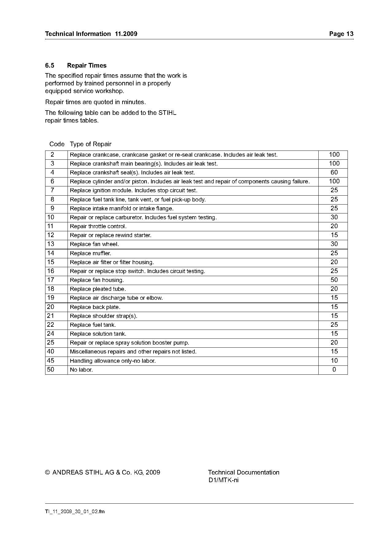
6.5     Repair Times
The specified repair times assume that the work is
performed by trained personnel in a properly
equipped service workshop.
Repair times are quoted in minutes.
The following table can be added to the STIHL
repair times tables.

 Code Type of Repair
 2       Replace crankcase, crankcase gasket or re-seal crankcase. Includes air leak test.                  100
 3       Replace crankshaft main bearing(s). Includes air leak test.                                        100
 4       Replace crankshaft seal(s). Includes air leak test.                                                 60
 6       Replace cylinder and/or piston. Includes air leak test and repair of components causing failure.   100
 7       Replace ignition module. Includes stop circuit test.                                                25
 8       Replace fuel tank line, tank vent, or fuel pick-up body.                                            25
 9       Replace intake manifold or intake flange.                                                           25
10       Repair or replace carburetor. Includes fuel system testing.                                         30
11       Repair throttle control.                                                                            20
12       Repair or replace rewind starter.                                                                   15
13       Replace fan wheel.                                                                                  30
14       Replace muffler.                                                                                    25
15       Replace air filter or filter housing.                                                               20
16       Repair or replace stop switch. Includes circuit testing.                                            25
17       Replace fan housing.                                                                                50
18       Replace pleated tube.                                                                               20
19       Replace air discharge tube or elbow.                                                                15
20       Replace back plate.                                                                                 15
21       Replace shoulder strap(s).                                                                          15
22       Replace fuel tank.                                                                                  25
24       Replace solution tank.                                                                              15
25       Repair or replace spray solution booster pump.                                                      20
40       Miscellaneous repairs and other repairs not listed.                                                 15
45       Handling allowance only-no labor.                                                                   10
50       No labor.                                                                                            0

© ANDREAS STIHL AG & Co. KG, 2009                                   Technical Documentation
                                                                    D1/MTK-ni

TI_11_2009_30_01_02.fm
Most of these PDFs embed fonts with a shifted character map, so the text above was recovered rather than copied — read it as a faithful but imperfect transcription, and treat the page image above each block as the authority where the two disagree — the figures exist only there, because they are vector drawings that text extraction cannot keep.