Technical Information · issue 19 of 2009
Brushcutter STIHL FS 90, 100, 110, 130; Brushcutter STIHL FS 310; KombiEngine STIHL KM 90, 100, 110, 130; Edger FC 90, 95, 100, 110; Pole pruner STIHL HT 100, 101, 130, 131; Hedge trimmer STIHL HL 90 K, 95, 95 K, 100, 100 K
IssueTI 19/2009
Part changes (3)
| Was | Becomes | What the bulletin says |
|---|---|---|
| 4182 967 3700 | 0000 967 3743 | 2 HT 100, 130 The previous pictogram 4182 967 3700 is replaced by the pictogram 0000 967 3743. |
| 4180 350 0425 | 4180 350 0424 | 53 l) If the pictogram must be replaced in case of service, The previous fuel tank 4180 350 0425 is being then it should also be attached in the new position replaced by the version 4180 350 0424. |
| 0000 967 3749 | 0000 967 3605 | The previous pictogram 0000 967 3749 is being The new fuel tank 4180 350 0424 is without replaced by the version 0000 967 3605. |
Full text
Page 1 of 5
Text of page 1 — search, copy, screen readers
STIH)

Technical Information                                                                     19.2009

  Brushcutter STIHL FS 90, 100, 110, 130                                            – Series 4180
  Brushcutter STIHL FS 310                                                          – Series 4180
  KombiEngine STIHL KM 90, 100, 110, 130                                            – Series 4180
  Edger FC 90, 95, 100, 110                                                         – Series 4180
  Pole pruner STIHL HT 100, 101, 130, 131                                           – Series 4182
  Hedge trimmer STIHL HL 90 K, 95, 95 K, 100, 100 K                                 – Series 4280

  Contents
  1. FS 310: Fuel hose, connector
     (for informational purpose only)
  2. Warning pictogram HT and warning pictogram filler cap
  3. Summary

  1.     FS 310: Fuel hose, connector                            The hoses can be identified according to the
          (for informational purpose only)                       markings:
                                                                 Identification     Part number
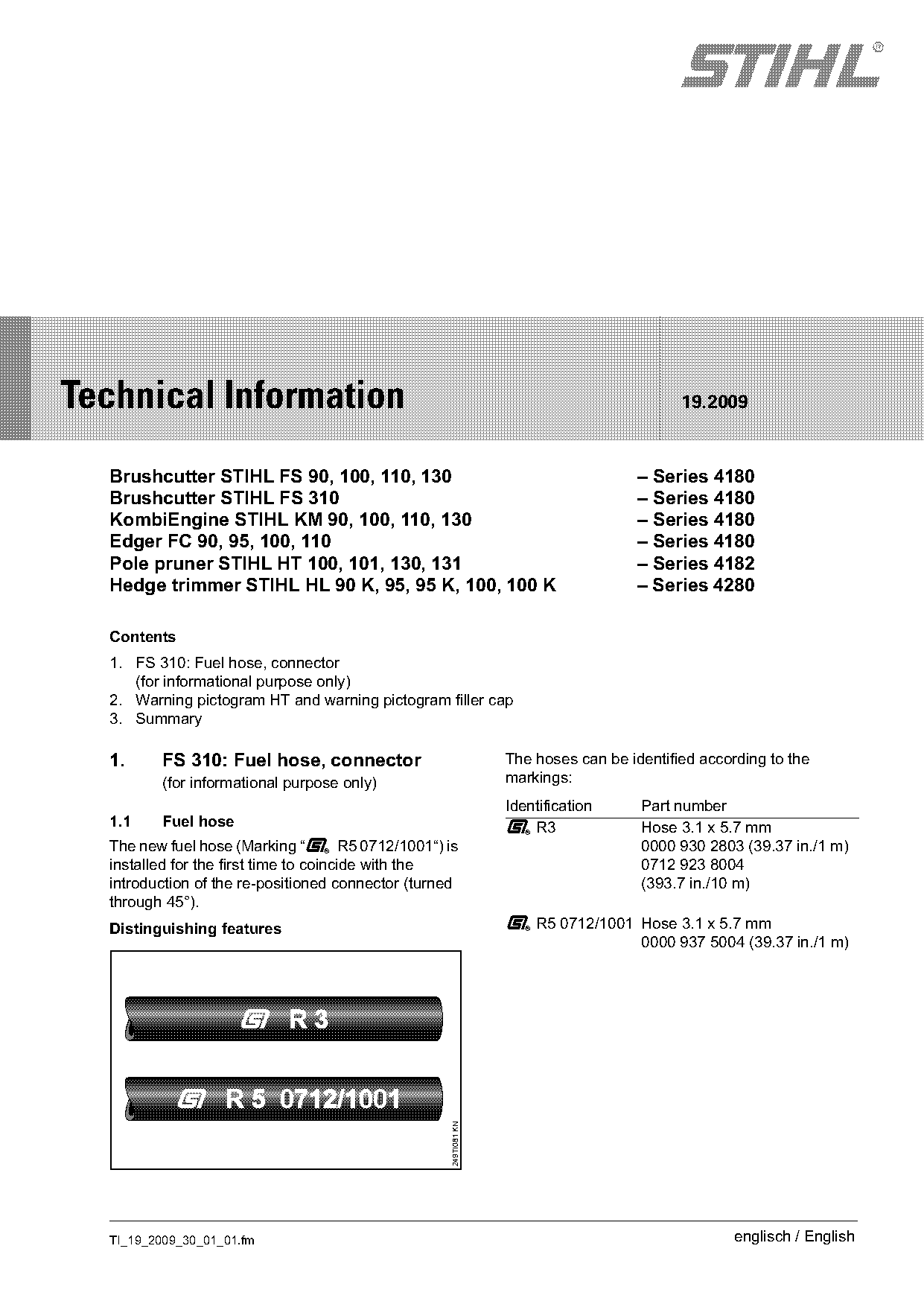
  1.1     Fuel hose                                              K R3               Hose 3.1 x 5.7 mm
  The new fuel hose (Marking “K R5 0712/1001“) is                                   0000 930 2803 (39.37 in./1 m)
  installed for the first time to coincide with the                                 0712 923 8004
  introduction of the re-positioned connector (turned                               (393.7 in./10 m)
  through 45°).
  Distinguishing features                                        K R5 0712/1001 Hose 3.1 x 5.7 mm
                                                                                0000 937 5004 (39.37 in./1 m)
                                                   249TI081 KN

  TI_19_2009_30_01_01.fm                                                                          englisch / English
Page 2 of 5
Text of page 2 — search, copy, screen readers
Page 2                                                                               Technical Information 19.2009

1.2      Length of the fuel hoses                                  1.3     Suction hose alignment
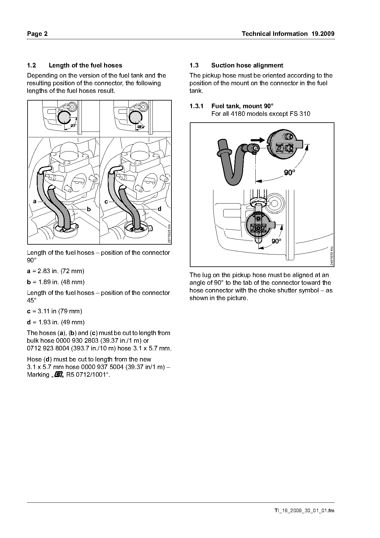
Depending on the version of the fuel tank and the                  The pickup hose must be oriented according to the
resulting position of the connector, the following                 position of the mount on the connector in the fuel
lengths of the fuel hoses result.                                  tank.

                                                                   1.3.1   Fuel tank, mount 90°
                                                                           For all 4180 models except FS 310

  a                         c
                       b                       d
                                                     237TI025 KN

                                                                                                                     249TI070 KN
Length of the fuel hoses – position of the connector
90°
a = 2.83 in. (72 mm)
                                                                   The lug on the pickup hose must be aligned at an
b = 1.89 in. (48 mm)                                               angle of 90° to the tab of the connector toward the
Length of the fuel hoses – position of the connector               hose connector with the choke shutter symbol – as
45°                                                                shown in the picture.

c = 3.11 in (79 mm)
d = 1.93 in. (49 mm)
The hoses (a), (b) and (c) must be cut to length from
bulk hose 0000 930 2803 (39.37 in./1 m) or
0712 923 8004 (393.7 in./10 m) hose 3.1 x 5.7 mm.
Hose (d) must be cut to length from the new
3.1 x 5.7 mm hose 0000 937 5004 (39.37 in/1 m) –
Marking „K R5 0712/1001“.

                                                                                                 TI_19_2009_30_01_01.fm
Page 3 of 5
Text of page 3 — search, copy, screen readers
Technical Information 19.2009                                                                                   Page 3

1.3.2   Fuel tank, mount 45°                                        2.      Warning pictogram HT and
        Only FS 310                                                         warning pictogram filler cap

                                                                    2.1     Warning pictogram HT

                                                                    2.1.1   HT 101, 131
                                                                    The warning pictogram 4182 967 3700 is being
                                                                    moved from the previous position on the shroud to
                                                                    the clamp on the shaft.

                                                                    2.1.2   HT 100, 130
                                                                    The previous pictogram 4182 967 3700 is replaced
                                                                    by the pictogram 0000 967 3743. Simultaneously,
                                                                    the pictogram is being moved from the shroud to the
                                                                    shaft.

                                                                    2.1.3   Position
                                                      249TI071 KN

The lug on the pickup hose must be aligned at an
angle of 45° to the tab of the connector toward the
hose connector with the choke shutter symbol – as
shown in the picture.
                                                                                                            c


                                                                                                                     246TI008 KN
                                                                     a                     a

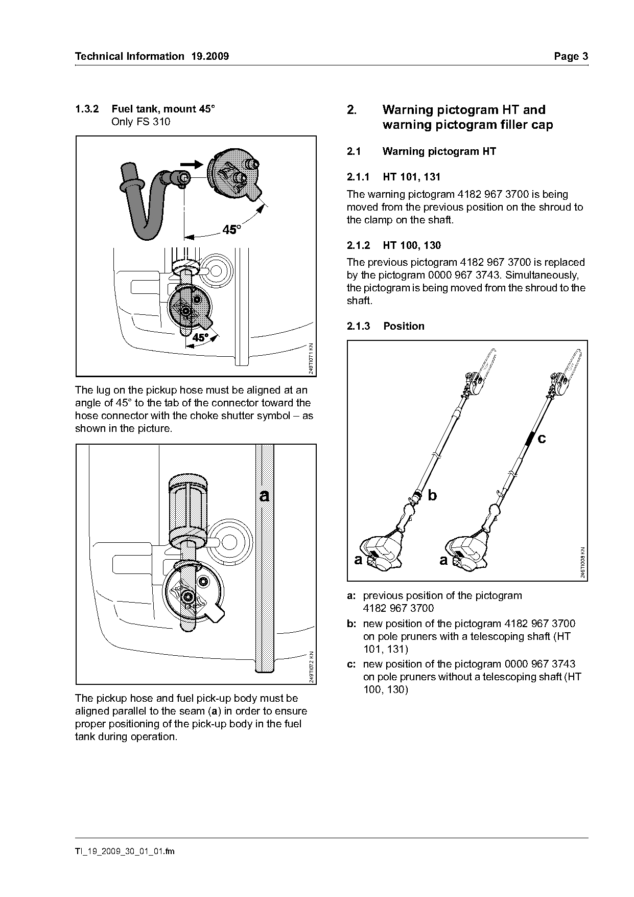
                                                                    a: previous position of the pictogram
                                                                       4182 967 3700
                                                                    b: new position of the pictogram 4182 967 3700
                                                                       on pole pruners with a telescoping shaft (HT
                                                                       101, 131)
                                                      249TI072 KN

                                                                    c: new position of the pictogram 0000 967 3743
                                                                       on pole pruners without a telescoping shaft (HT
                                                                       100, 130)
The pickup hose and fuel pick-up body must be
aligned parallel to the seam (a) in order to ensure
proper positioning of the pick-up body in the fuel
tank during operation.

TI_19_2009_30_01_01.fm
Page 4 of 5
Text of page 4 — search, copy, screen readers
Page 4                                                                              Technical Information 19.2009

2.1.4    Spare parts/service notes                               2.2.3   Fuel tank 1.12 pt (0.53 l)
If the pictogram must be replaced in case of service,            The previous fuel tank 4180 350 0425 is being
then it should also be attached in the new position              replaced by the version 4180 350 0424.
on older machines, see b 2.1.3
                                                                 Spare parts/service notes
                                                                 The previous fuel tank 4180 350 0425 with
                                                                 pictogram 0000 967 3749 will remain available for
2.2      Warning pictogram filler cap
                                                                 approx. five years for older machines.
The previous pictogram 0000 967 3749 is being
                                                                 The new fuel tank 4180 350 0424 is without
replaced by the version 0000 967 3605. The new
                                                                 pictogram 0000 967 3749 and can only be
pictogram is attached to the shroud.
                                                                 combined with machines that have pictogram
                                                                 0000 967 3605 on the shroud.
2.2.1    Shroud
The previous shroud 4180 080 1600 without                        2.3     Service notes
pictogram is being replaced by the shroud
                                                                 After all service work on the machine, check for
4180 080 1604 with pictogram 0000 967 3605.
                                                                 completeness and condition of the warning
                                                                 pictograms. Add or replace warning pictograms if
2.2.2    Position
                                                                 necessary.


            a
                                                   273TI024 KN

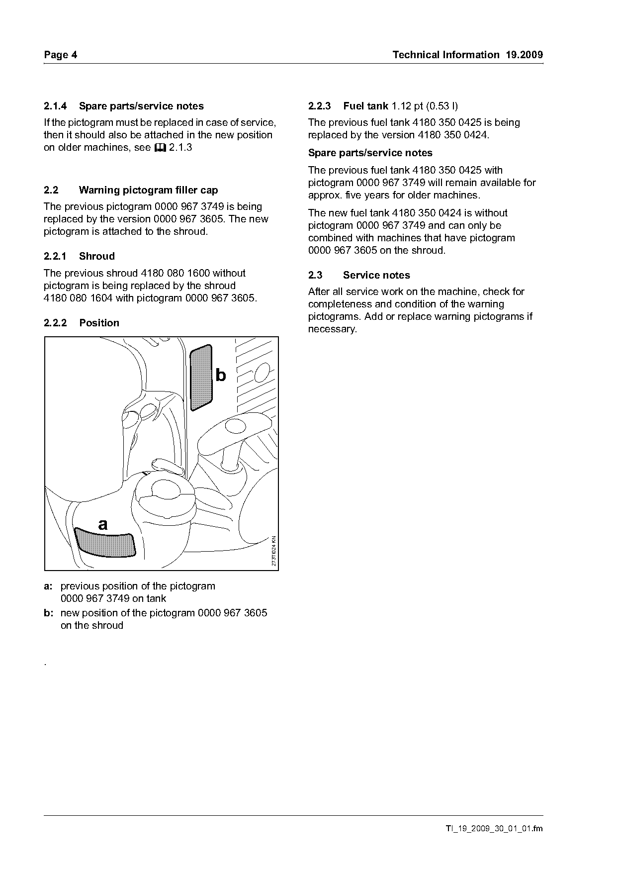
a: previous position of the pictogram
   0000 967 3749 on tank
b: new position of the pictogram 0000 967 3605
   on the shroud

.

                                                                                                TI_19_2009_30_01_01.fm
Page 5 of 5
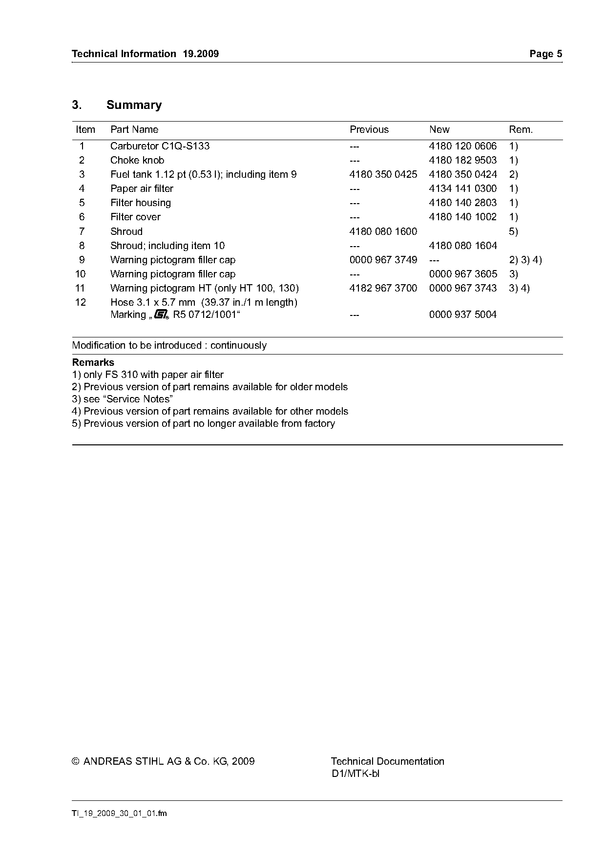
Text of page 5 — search, copy, screen readers
Technical Information 19.2009                                                                         Page 5

3.     Summary
Item    Part Name                                                Previous        New             Rem.
 1      Carburetor C1Q-S133                                      ---             4180 120 0606   1)
 2      Choke knob                                               ---             4180 182 9503   1)
 3      Fuel tank 1.12 pt (0.53 l); including item 9             4180 350 0425   4180 350 0424   2)
 4      Paper air filter                                         ---             4134 141 0300   1)
 5      Filter housing                                           ---             4180 140 2803   1)
 6      Filter cover                                             ---             4180 140 1002   1)
 7      Shroud                                                   4180 080 1600                   5)
 8      Shroud; including item 10                                ---             4180 080 1604
 9      Warning pictogram filler cap                             0000 967 3749   ---             2) 3) 4)
10      Warning pictogram filler cap                             ---             0000 967 3605   3)
11      Warning pictogram HT (only HT 100, 130)                  4182 967 3700   0000 967 3743   3) 4)
12      Hose 3.1 x 5.7 mm (39.37 in./1 m length)
        Marking „K R5 0712/1001“                                 ---             0000 937 5004

Modification to be introduced : continuously
Remarks
1) only FS 310 with paper air filter
2) Previous version of part remains available for older models
3) see “Service Notes”
4) Previous version of part remains available for other models
5) Previous version of part no longer available from factory

© ANDREAS STIHL AG & Co. KG, 2009                         Technical Documentation
                                                          D1/MTK-bl

TI_19_2009_30_01_01.fm
Most of these PDFs embed fonts with a shifted character map, so the text above was recovered rather than copied — read it as a faithful but imperfect transcription, and treat the page image above each block as the authority where the two disagree — the figures exist only there, because they are vector drawings that text extraction cannot keep.