Technical Information · issue 25 of 2009
New STIHL FS 310 Brushcutter
IssueTI 25/2009
Full text
Page 1 of 9
Text of page 1 — search, copy, screen readers
STIH)

Draft
USA only – Market Launch

Technical Information                                          25.2009

   New STIHL FS 310 Brushcutter – Series 4180

   Contents
   1.   Technical Description
   2.   Specifications
   3.   Cutting Tools
   4.   Accessories
   5.   Service Accessories
   6.   Service Note

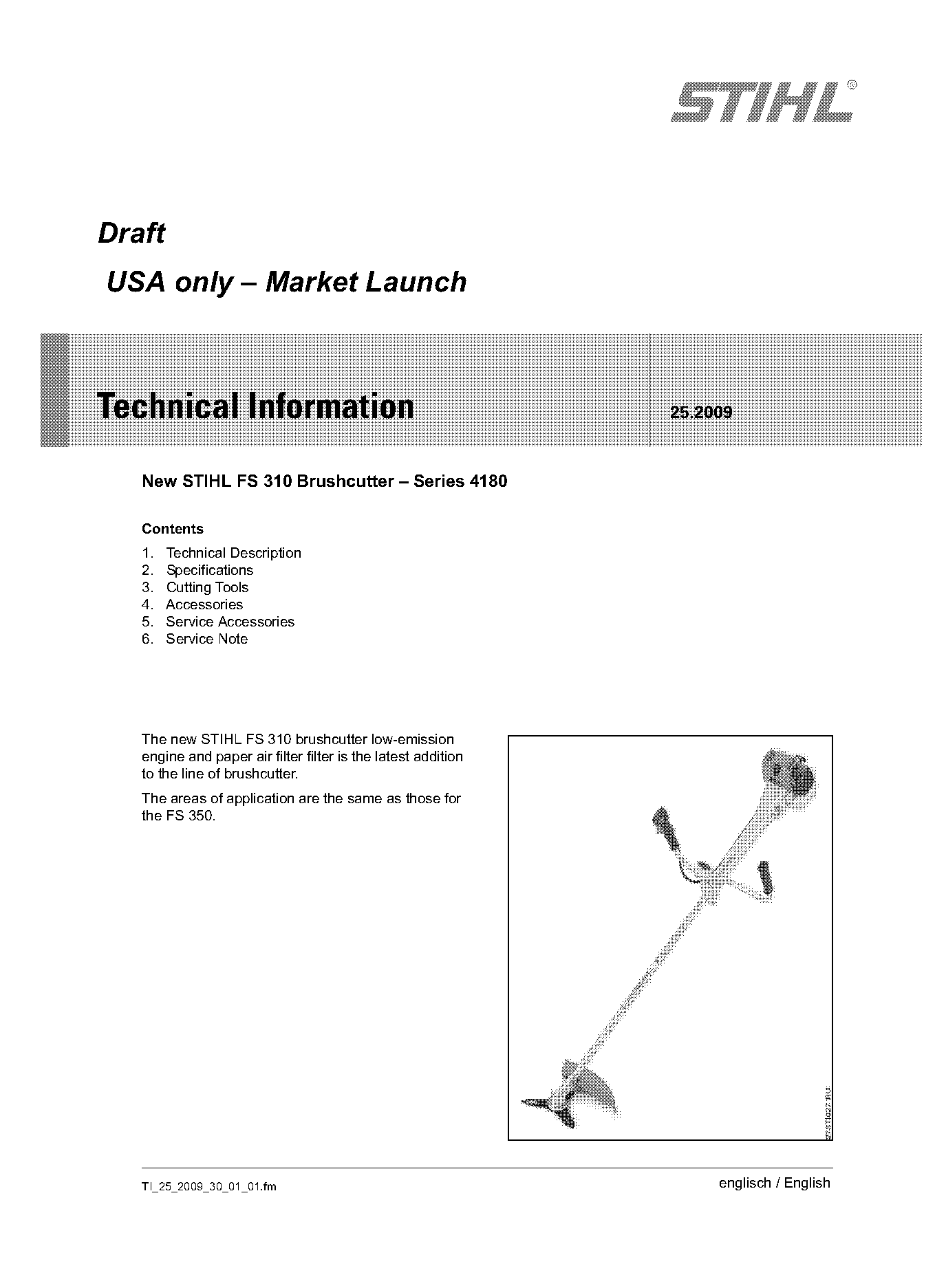
   The new STIHL FS 310 brushcutter low-emission
   engine and paper air filter filter is the latest addition
   to the line of brushcutter.
   The areas of application are the same as those for
   the FS 350.

   TI_25_2009_30_01_01.fm                                           englisch / English
Page 2 of 9
Text of page 2 — search, copy, screen readers
Page 2                                                                                Technical Information 25.2009

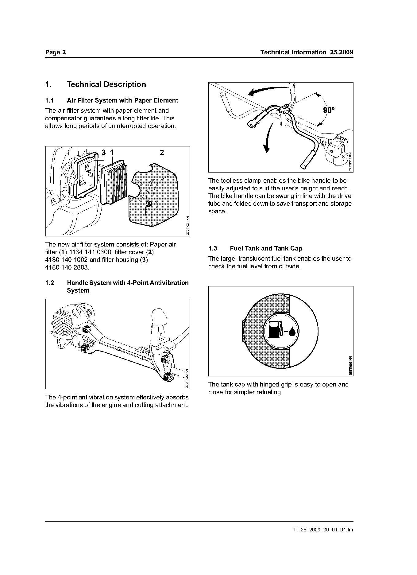
1.       Technical Description

1.1      Air Filter System with Paper Element
The air filter system with paper element and
compensator guarantees a long filter life. This
allows long periods of uninterrupted operation.

                    3 1                   2

                                                                                                                     273TI003 KN
                                                                   The toolless clamp enables the bike handle to be
                                                                   easily adjusted to suit the user's height and reach.
                                                                   The bike handle can be swung in line with the drive
                                                                   tube and folded down to save transport and storage
                                                                   space.
                                                     273TI021 KN

The new air filter system consists of: Paper air
                                                                   1.3    Fuel Tank and Tank Cap
filter (1) 4134 141 0300, filter cover (2)
4180 140 1002 and filter housing (3)                               The large, translucent fuel tank enables the user to
4180 140 2803.                                                     check the fuel level from outside.

1.2      Handle System with 4-Point Antivibration
         System
                                                   273TI002 KN

                                                                   The tank cap with hinged grip is easy to open and
                                                                   close for simpler refueling.
The 4-point antivibration system effectively absorbs
the vibrations of the engine and cutting attachment.

                                                                                                 TI_25_2009_30_01_01.fm
Page 3 of 9
Text of page 3 — search, copy, screen readers
Technical Information 25.2009                                                                         Page 3

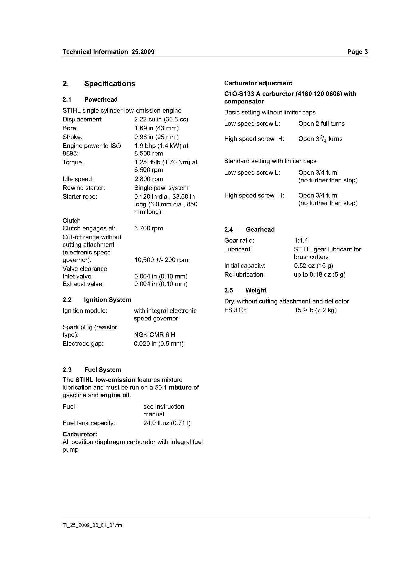
2.      Specifications                                 Carburetor adjustment
                                                       C1Q-S133 A carburetor (4180 120 0606) with
2.1     Powerhead                                      compensator
STIHL single cylinder low-emission engine              Basic setting without limiter caps
Displacement:            2.22 cu.in (36.3 cc)
                                                       Low speed screw L:         Open 2 full turns
Bore:                    1.69 in (43 mm)
Stroke:                  0.98 in (25 mm)               High speed screw H:        Open 33/4 turns
Engine power to ISO      1.9 bhp (1.4 kW) at
8893:                    8,500 rpm
Torque:                  1.25 ft/lb (1.70 Nm) at       Standard setting with limiter caps
                         6,500 rpm                     Low speed screw L:         Open 3/4 turn
Idle speed:              2,800 rpm                                                (no further than stop)
Rewind starter:          Single pawl system
Starter rope:            0.120 in dia., 33.50 in       High speed screw H:        Open 3/4 turn
                         long (3.0 mm dia., 850                                   (no further than stop)
                         mm long)
Clutch
Clutch engages at:       3,700 rpm                     2.4     Gearhead
Cut-off range without
                                                       Gear ratio:              1:1.4
cutting attachment
(electronic speed                                      Lubricant:               STIHL gear lubricant for
governor):               10,500 +/- 200 rpm                                     brushcutters
                                                       Initial capacity:        0.52 oz (15 g)
Valve clearance
Inlet valve:             0.004 in (0.10 mm)            Re-lubrication:          up to 0.18 oz (5 g)
Exhaust valve:           0.004 in (0.10 mm)
                                                       2.5     Weight
2.2     Ignition System                                Dry, without cutting attachment and deflector
Ignition module:          with integral electronic     FS 310:                   15.9 lb (7.2 kg)
                          speed governor
Spark plug (resistor
type):                    NGK CMR 6 H
Electrode gap:            0.020 in (0.5 mm)

2.3     Fuel System
The STIHL low-emission features mixture
lubrication and must be run on a 50:1 mixture of
gasoline and engine oil.
Fuel:                        see instruction
                             manual
Fuel tank capacity:          24.0 fl.oz (0.71 l)
Carburetor:
All position diaphragm carburetor with integral fuel
pump

TI_25_2009_30_01_01.fm
Page 4 of 9
Text of page 4 — search, copy, screen readers
Page 4                                                                           Technical Information 25.2009

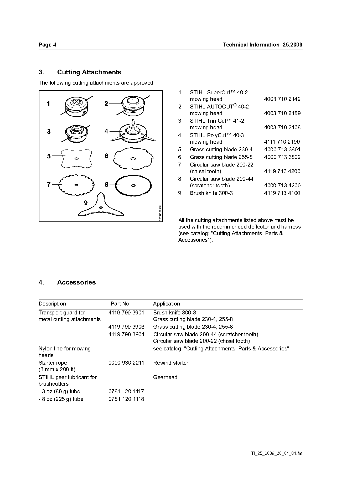
3.       Cutting Attachments
The following cutting attachments are approved
                                                                1   STIHL SuperCut™ 40-2
                                                                    mowing head                  4003 710 2142
     1                      2                                   2   STIHL AUTOCUT® 40-2
                                                                    mowing head                  4003 710 2189
                                                                3   STIHL TrimCut™ 41-2
                                                                    mowing head                  4003 710 2108
     3                      4
                                                                4   STIHL PolyCut™ 40-3
                                                                    mowing head                  4111 710 2190
                                                                5   Grass cutting blade 230-4    4000 713 3801
     5                      6                                   6   Grass cutting blade 255-8    4000 713 3802
                                                                7   Circular saw blade 200-22
                                                                    (chisel tooth)               4119 713 4200
                                                                8   Circular saw blade 200-44
     7                      8                                       (scratcher tooth)            4000 713 4200
                                                                9   Brush knife 300-3            4119 713 4100
                  9
                                                  273TI026 KN

                                                                All the cutting attachments listed above must be
                                                                used with the recommended deflector and harness
                                                                (see catalog: "Cutting Attachments, Parts &
                                                                Accessories").

4.       Accessories

Description                     Part No.        Application
Transport guard for             4116 790 3901   Brush knife 300-3
metal cutting attachments                       Grass cutting blade 230-4, 255-8
                                4119 790 3906   Grass cutting blade 230-4, 255-8
                                4119 790 3901   Circular saw blade 200-44 (scratcher tooth)
                                                Circular saw blade 200-22 (chisel tooth)
Nylon line for mowing                           see catalog: "Cutting Attachments, Parts & Accessories"
heads
Starter rope                    0000 930 2211   Rewind starter
(3 mm x 200 ft)
STIHL gear lubricant for                        Gearhead
brushcutters
- 3 oz (80 g) tube              0781 120 1117
- 8 oz (225 g) tube             0781 120 1118

                                                                                            TI_25_2009_30_01_01.fm
Page 5 of 9
Text of page 5 — search, copy, screen readers
Technical Information 25.2009                                                                         Page 5

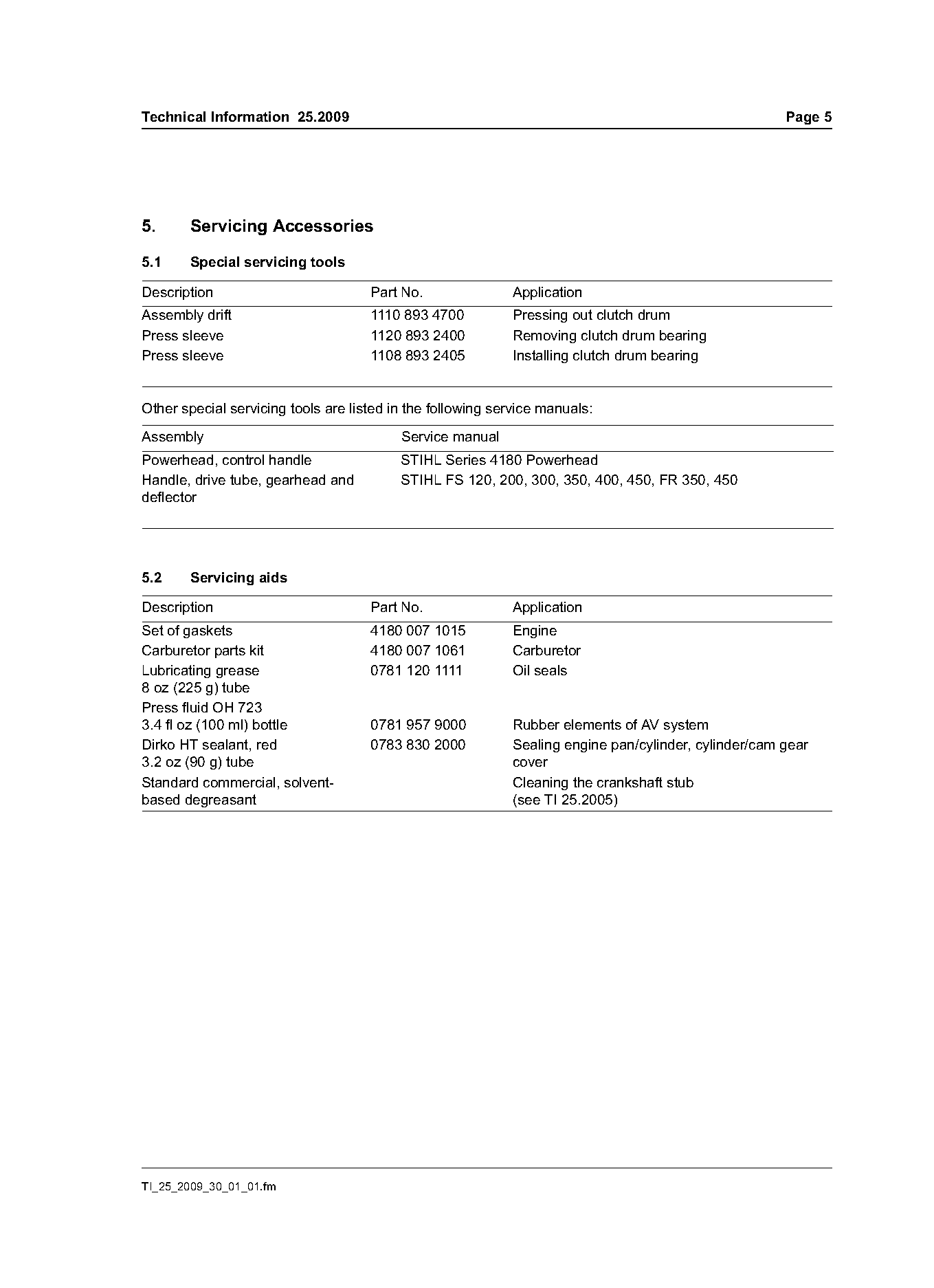
5.     Servicing Accessories

5.1    Special servicing tools

Description                          Part No.               Application
Assembly drift                       1110 893 4700          Pressing out clutch drum
Press sleeve                         1120 893 2400          Removing clutch drum bearing
Press sleeve                         1108 893 2405          Installing clutch drum bearing

Other special servicing tools are listed in the following service manuals:
Assembly                                  Service manual
Powerhead, control handle                 STIHL Series 4180 Powerhead
Handle, drive tube, gearhead and          STIHL FS 120, 200, 300, 350, 400, 450, FR 350, 450
deflector

5.2    Servicing aids

Description                          Part No.               Application
Set of gaskets                       4180 007 1015          Engine
Carburetor parts kit                 4180 007 1061          Carburetor
Lubricating grease                   0781 120 1111          Oil seals
8 oz (225 g) tube
Press fluid OH 723
3.4 fl oz (100 ml) bottle            0781 957 9000          Rubber elements of AV system
Dirko HT sealant, red                0783 830 2000          Sealing engine pan/cylinder, cylinder/cam gear
3.2 oz (90 g) tube                                          cover
Standard commercial, solvent-                               Cleaning the crankshaft stub
based degreasant                                            (see TI 25.2005)

TI_25_2009_30_01_01.fm
Page 6 of 9
Text of page 6 — search, copy, screen readers
Page 6                                                                                     Technical Information 25.2009

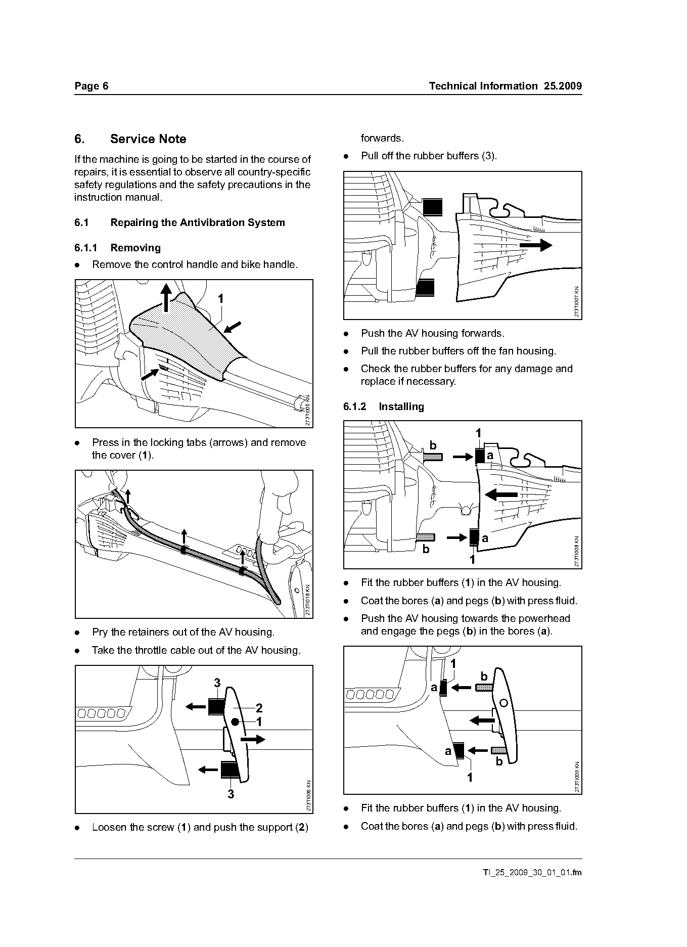
6.       Service Note                                                     forwards.

If the machine is going to be started in the course of                .   Pull off the rubber buffers (3).
repairs, it is essential to observe all country-specific
safety regulations and the safety precautions in the
instruction manual.

6.1      Repairing the Antivibration System

6.1.1    Removing
.     Remove the control handle and bike handle.

                                                                                                                                273TI007 KN
                                 1

                                                                      .   Push the AV housing forwards.
                                                                      .   Pull the rubber buffers off the fan housing.
                                                                      .   Check the rubber buffers for any damage and
                                                                          replace if necessary.
                                                       273TI005 KN

                                                                      6.1.2   Installing

                                                                                                        1
.     Press in the locking tabs (arrows) and remove                                        b
      the cover (1).                                                                                        a


                                                                                                                                273TI008 KN
                                                                                        b
                                                                                                    1
                                                                      .   Fit the rubber buffers (1) in the AV housing.
                                                       273TI018 KN

                                                                      .   Coat the bores (a) and pegs (b) with press fluid.
                                                                      .   Push the AV housing towards the powerhead
.     Pry the retainers out of the AV housing.                            and engage the pegs (b) in the bores (a).
.     Take the throttle cable out of the AV housing.
                                                                                                1
                                                                                                        b
                                 3                                                          a
                                           2
                                           1

                                                                                                a
                                                                                                                b
                                                                                                                                 273TI009 KN

                                                                                                    1
                                                        273TI006 KN

                                     3
                                                                      .   Fit the rubber buffers (1) in the AV housing.
.     Loosen the screw (1) and push the support (2)                   .   Coat the bores (a) and pegs (b) with press fluid.

                                                                                                            TI_25_2009_30_01_01.fm
Page 7 of 9
Text of page 7 — search, copy, screen readers
Technical Information 25.2009                                                                                        Page 7

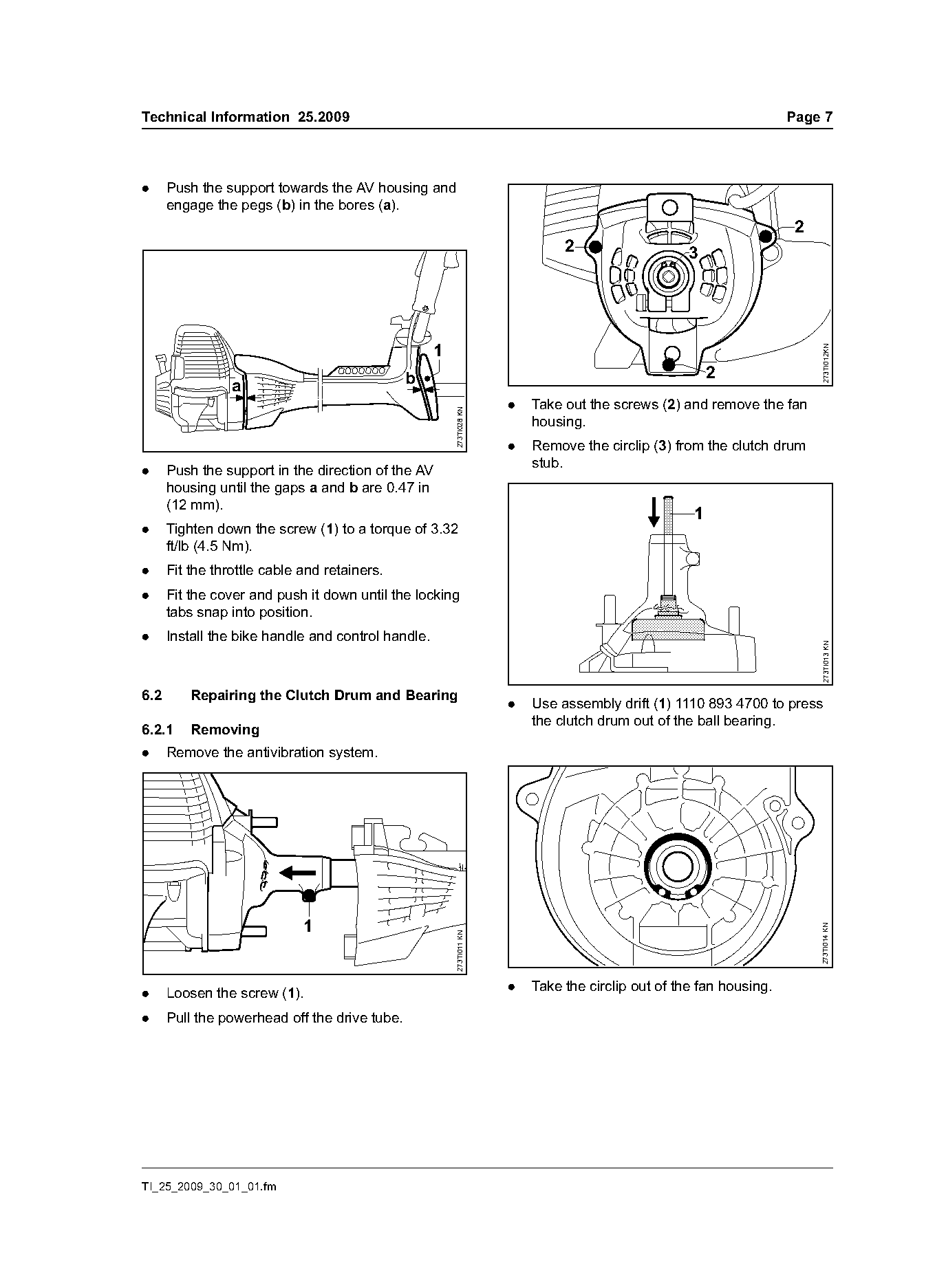
.     Push the support towards the AV housing and
      engage the pegs (b) in the bores (a).
                                                                                                                      2
                                                                               2                    3


                                                                                                                           273TI012KN
                                               b                                                         2
                 a
                                                                      .   Take out the screws (2) and remove the fan

                                                        273TI028 KN
                                                                          housing.
                                                                      .   Remove the circlip (3) from the clutch drum
                                                                          stub.
.     Push the support in the direction of the AV
      housing until the gaps a and b are 0.47 in
      (12 mm).
                                                                                                     1
.     Tighten down the screw (1) to a torque of 3.32
      ft/lb (4.5 Nm).
.     Fit the throttle cable and retainers.
.     Fit the cover and push it down until the locking
      tabs snap into position.
.     Install the bike handle and control handle.

                                                                                                                           273TI013 KN
6.2       Repairing the Clutch Drum and Bearing
                                                                      .   Use assembly drift (1) 1110 893 4700 to press
                                                                          the clutch drum out of the ball bearing.
6.2.1     Removing
.     Remove the antivibration system.

                             1
                                                                                                                          273TI014 KN
                                                        273TI011 KN

.     Loosen the screw (1).                                           .   Take the circlip out of the fan housing.

.     Pull the powerhead off the drive tube.

TI_25_2009_30_01_01.fm
Page 8 of 9
Text of page 8 — search, copy, screen readers
Page 8                                                                                   Technical Information 25.2009

                                                                                                        1
                                1

                                                                                                                          273TI016 KN
                                                      273TI019 KN
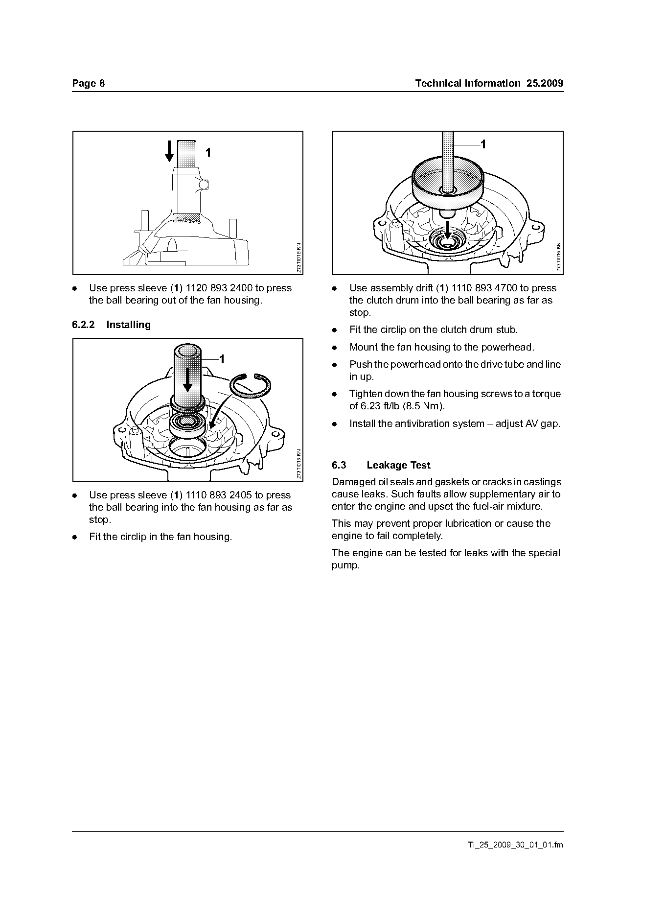
.   Use press sleeve (1) 1120 893 2400 to press                     .     Use assembly drift (1) 1110 893 4700 to press
    the ball bearing out of the fan housing.                              the clutch drum into the ball bearing as far as
                                                                          stop.
6.2.2    Installing
                                                                    .     Fit the circlip on the clutch drum stub.
                                                                    .     Mount the fan housing to the powerhead.
                                    1                               .     Push the powerhead onto the drive tube and line
                                                                          in up.
                                                                    .     Tighten down the fan housing screws to a torque
                                                                          of 6.23 ft/lb (8.5 Nm).
                                                                    .     Install the antivibration system – adjust AV gap.
                                                      273TI015 KN

                                                                    6.3       Leakage Test
                                                                    Damaged oil seals and gaskets or cracks in castings
.   Use press sleeve (1) 1110 893 2405 to press                     cause leaks. Such faults allow supplementary air to
    the ball bearing into the fan housing as far as                 enter the engine and upset the fuel-air mixture.
    stop.                                                           This may prevent proper lubrication or cause the
.   Fit the circlip in the fan housing.                             engine to fail completely.
                                                                    The engine can be tested for leaks with the special
                                                                    pump.

                                                                                                      TI_25_2009_30_01_01.fm
Page 9 of 9
Text of page 9 — search, copy, screen readers
Technical Information 25.2009                                                                   Page 9

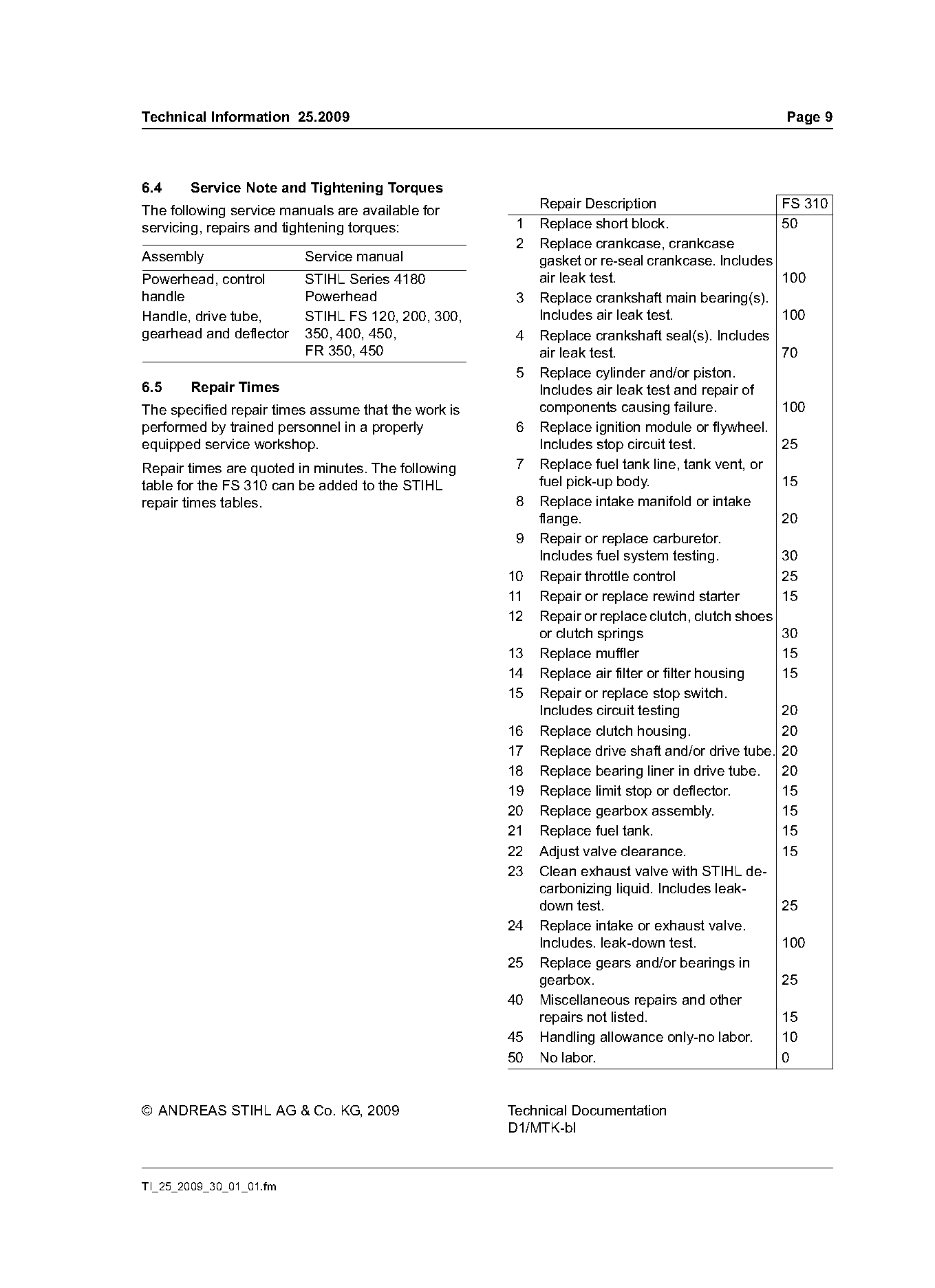
6.4    Service Note and Tightening Torques
                                                          Repair Description                     FS 310
The following service manuals are available for
servicing, repairs and tightening torques:            1   Replace short block.                   50
                                                      2   Replace crankcase, crankcase
Assembly                 Service manual                   gasket or re-seal crankcase. Includes
Powerhead, control       STIHL Series 4180                air leak test.                         100
handle                   Powerhead                    3   Replace crankshaft main bearing(s).
Handle, drive tube,      STIHL FS 120, 200, 300,          Includes air leak test.                100
gearhead and deflector   350, 400, 450,               4   Replace crankshaft seal(s). Includes
                         FR 350, 450                      air leak test.                         70
                                                      5   Replace cylinder and/or piston.
6.5    Repair Times                                       Includes air leak test and repair of
The specified repair times assume that the work is        components causing failure.            100
performed by trained personnel in a properly          6   Replace ignition module or flywheel.
equipped service workshop.                                Includes stop circuit test.            25
Repair times are quoted in minutes. The following     7   Replace fuel tank line, tank vent, or
table for the FS 310 can be added to the STIHL            fuel pick-up body.                     15
repair times tables.                                  8   Replace intake manifold or intake
                                                          flange.                                20
                                                      9   Repair or replace carburetor.
                                                          Includes fuel system testing.          30
                                                     10   Repair throttle control                25
                                                     11   Repair or replace rewind starter       15
                                                     12   Repair or replace clutch, clutch shoes
                                                          or clutch springs                      30
                                                     13   Replace muffler                        15
                                                     14   Replace air filter or filter housing   15
                                                     15   Repair or replace stop switch.
                                                          Includes circuit testing               20
                                                     16   Replace clutch housing.                20
                                                     17   Replace drive shaft and/or drive tube. 20
                                                     18   Replace bearing liner in drive tube. 20
                                                     19   Replace limit stop or deflector.       15
                                                     20   Replace gearbox assembly.              15
                                                     21   Replace fuel tank.                     15
                                                     22   Adjust valve clearance.                15
                                                     23   Clean exhaust valve with STIHL de-
                                                          carbonizing liquid. Includes leak-
                                                          down test.                             25
                                                     24   Replace intake or exhaust valve.
                                                          Includes. leak-down test.              100
                                                     25   Replace gears and/or bearings in
                                                          gearbox.                               25
                                                     40   Miscellaneous repairs and other
                                                          repairs not listed.                    15
                                                     45   Handling allowance only-no labor.      10
                                                     50   No labor.                              0

© ANDREAS STIHL AG & Co. KG, 2009                    Technical Documentation
                                                     D1/MTK-bl

TI_25_2009_30_01_01.fm
Most of these PDFs embed fonts with a shifted character map, so the text above was recovered rather than copied — read it as a faithful but imperfect transcription, and treat the page image above each block as the authority where the two disagree — the figures exist only there, because they are vector drawings that text extraction cannot keep.