Technical Information · issue 35 of 2009
Guard with defined adjustment range; Belt guard, screw; Instruction labels; Summary
IssueTI 35/2009
Part changes (4)
| Was | Becomes | What the bulletin says |
|---|---|---|
| 4238 701 0200 | 4238 701 0203 | The previous versions of the cast arm Left: Previous versions of the guard 4238 701 0201 (TS 410) and cast arm Right: New versions of the guard 4238 701 0200 (TS 420) are being replaced by the new versions of the cast arm 4238 701 0203 The previous versions of the guard dia. |
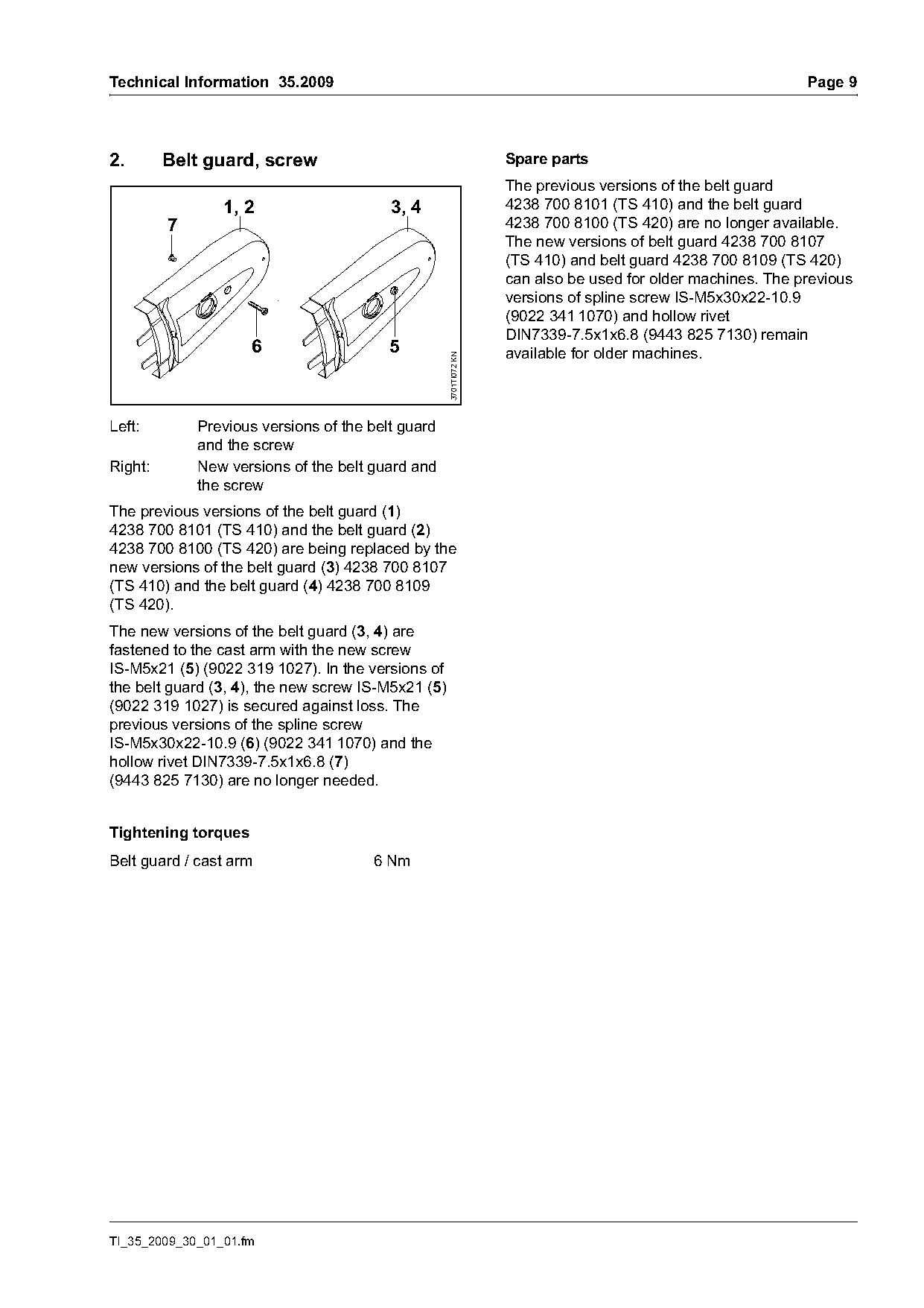
| 4238 700 8101 | 4238 700 8107 | 3701TI072 KN Left: Previous versions of the belt guard and the screw Right: New versions of the belt guard and the screw The previous versions of the belt guard (1) 4238 700 8101 (TS 410) and the belt guard (2) 4238 700 8100 (TS 420) are being replaced by the new versions of the belt guard (3) 4238 |
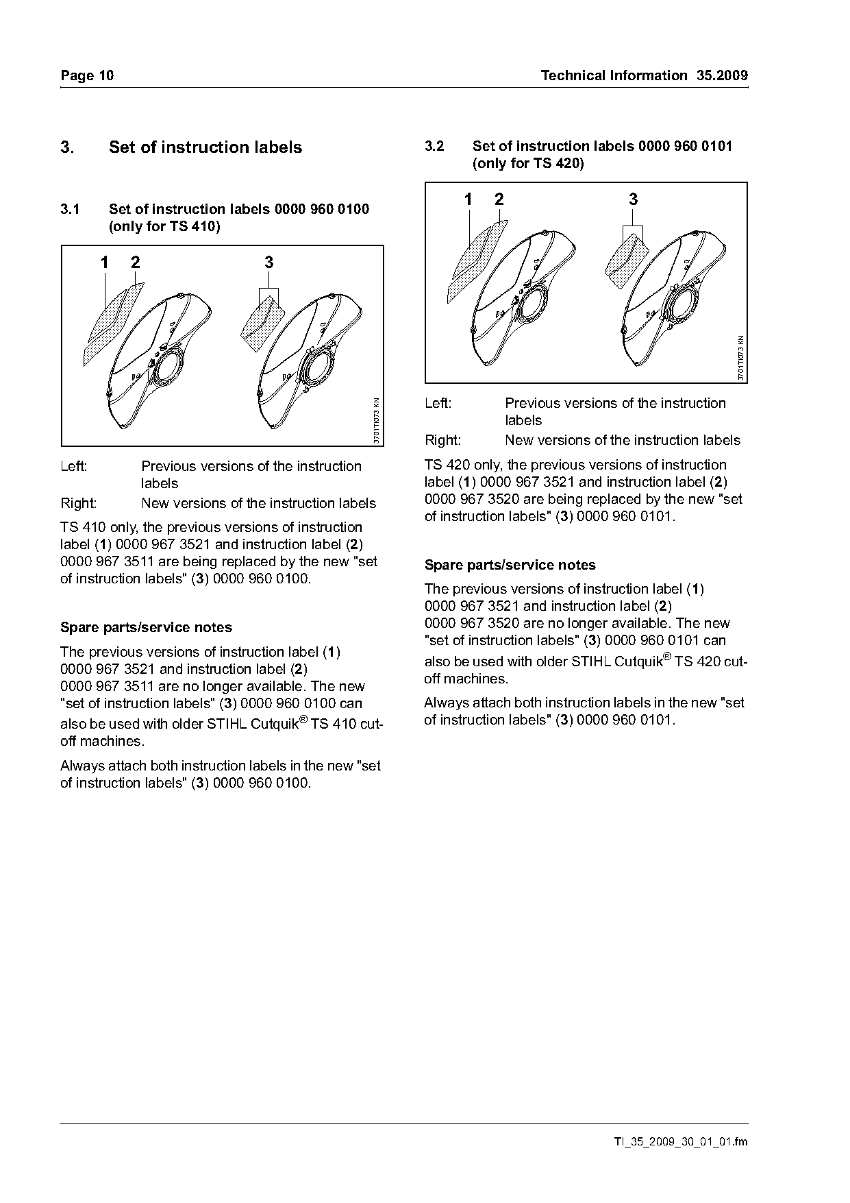
| 0000 967 3521 | 0000 960 0101 | labels Right: New versions of the instruction labels Left: Previous versions of the instruction TS 420 only, the previous versions of instruction labels label (1) 0000 967 3521 and instruction label (2) Right: New versions of the instruction labels 0000 967 3520 are being replaced by the new "set of |
| 0000 967 3521 | 0000 960 0100 | TS 410 only, the previous versions of instruction label (1) 0000 967 3521 and instruction label (2) 0000 967 3511 are being replaced by the new "set Spare parts/service notes of instruction labels" (3) 0000 960 0100. |
Full text
Page 1 of 11
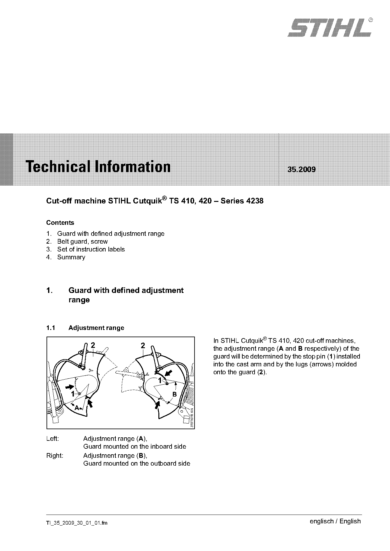
Text of page 1 — search, copy, screen readers
STIH)

Technical Information                                                                      35.2009

  Cut-off machine STIHL Cutquik® TS 410, 420 – Series 4238

  Contents
  1.    Guard with defined adjustment range
  2.    Belt guard, screw
  3.    Set of instruction labels
  4.    Summary

  1.       Guard with defined adjustment
           range

  1.1      Adjustment range
                                                                In STIHL Cutquik® TS 410, 420 cut-off machines,
                   2               2                            the adjustment range (A and B respectively) of the
                                                                guard will be determined by the stop pin (1) installed
                                                                into the cast arm and by the lugs (arrows) molded
                                                                onto the guard (2).
                                        1
            1                                 B

             A
                                                  370TI016 KN

  Left:          Adjustment range (A),
                 Guard mounted on the inboard side
  Right:         Adjustment range (B),
                 Guard mounted on the outboard side

  TI_35_2009_30_01_01.fm                                                                           englisch / English
Page 2 of 11
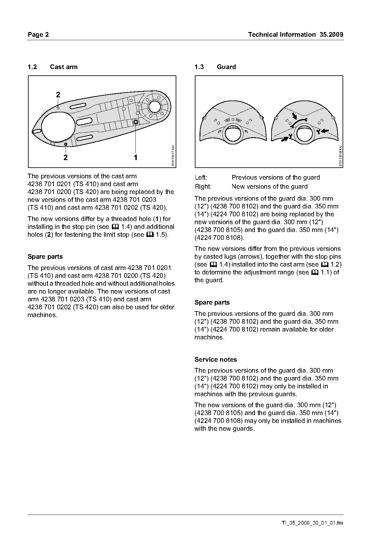
Text of page 2 — search, copy, screen readers
Page 2                                                                               Technical Information 35.2009

1.2      Cast arm                                                 1.3      Guard


                                                   3701TI017 KN

                                                                                                                     3701TI018 KN
              2                       1

The previous versions of the cast arm                             Left:         Previous versions of the guard
4238 701 0201 (TS 410) and cast arm                               Right:        New versions of the guard
4238 701 0200 (TS 420) are being replaced by the
new versions of the cast arm 4238 701 0203                        The previous versions of the guard dia. 300 mm
(TS 410) and cast arm 4238 701 0202 (TS 420).                     (12") (4238 700 8102) and the guard dia. 350 mm
                                                                  (14") (4224 700 8102) are being replaced by the
The new versions differ by a threaded hole (1) for                new versions of the guard dia. 300 mm (12")
installing in the stop pin (see b 1.4) and additional             (4238 700 8105) and the guard dia. 350 mm (14")
holes (2) for fastening the limit stop (see b 1.5).               (4224 700 8108).
                                                                  The new versions differ from the previous versions
Spare parts                                                       by casted lugs (arrows), together with the stop pins
                                                                  (see b 1.4) installed into the cast arm (see b 1.2)
The previous versions of cast arm 4238 701 0201
                                                                  to determine the adjustment range (see b 1.1) of
(TS 410) and cast arm 4238 701 0200 (TS 420)
                                                                  the guard.
without a threaded hole and without additional holes
are no longer available. The new versions of cast
arm 4238 701 0203 (TS 410) and cast arm
                                                                  Spare parts
4238 701 0202 (TS 420) can also be used for older
machines.                                                         The previous versions of the guard dia. 300 mm
                                                                  (12") (4238 700 8102) and the guard dia. 350 mm
                                                                  (14") (4224 700 8102) remain available for older
                                                                  machines.

                                                                  Service notes
                                                                  The previous versions of the guard dia. 300 mm
                                                                  (12") (4238 700 8102) and the guard dia. 350 mm
                                                                  (14") (4224 700 8102) may only be installed in
                                                                  machines with the previous guards.
                                                                  The new versions of the guard dia. 300 mm (12")
                                                                  (4238 700 8105) and the guard dia. 350 mm (14")
                                                                  (4224 700 8108) may only be installed in machines
                                                                  with the new guards.

                                                                                                TI_35_2009_30_01_01.fm
Page 3 of 11
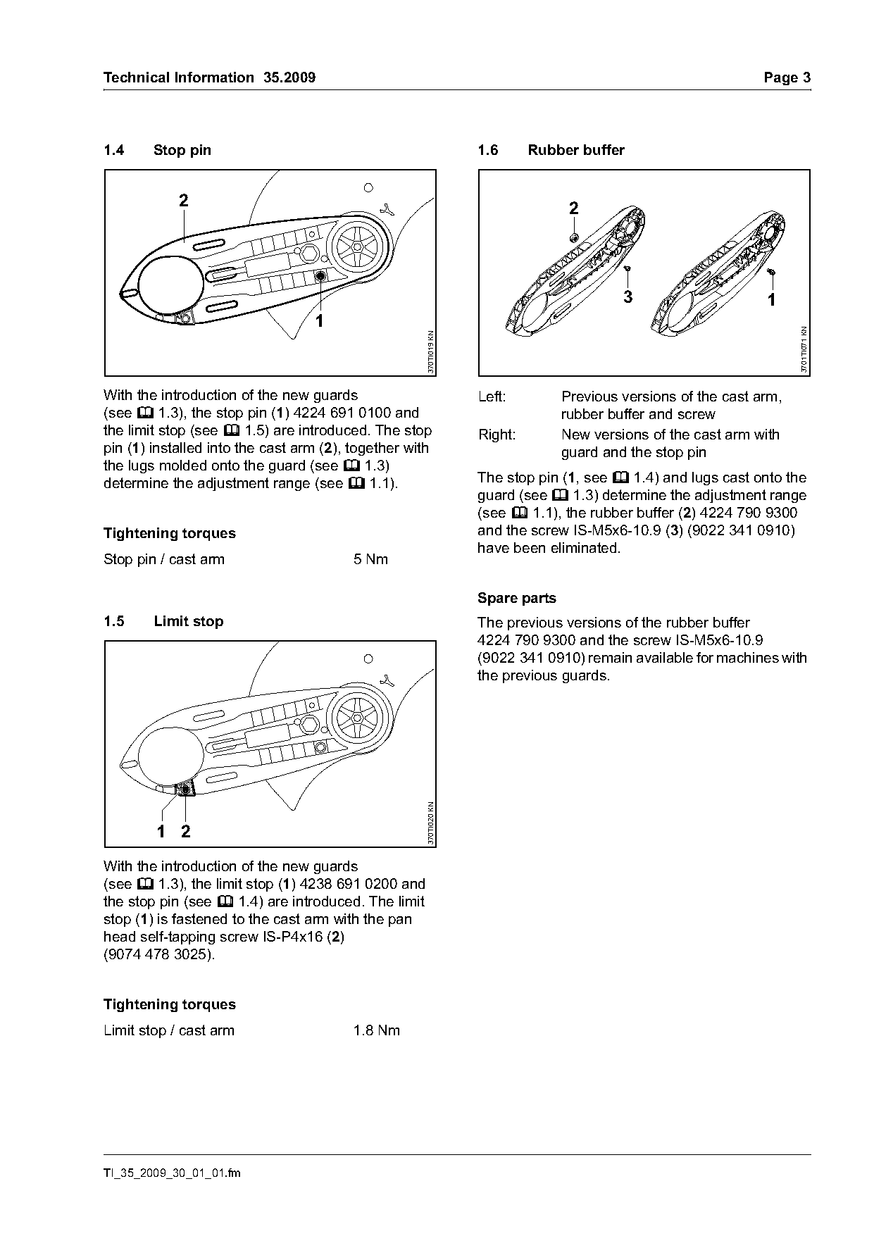
Text of page 3 — search, copy, screen readers
Technical Information 35.2009                                                                                   Page 3

1.4     Stop pin                                                   1.6      Rubber buffer

            2                                                                     2

                                                                                          3                     1
                                  1

                                                                                                                      3701TI071 KN
                                                     370TI019 KN
With the introduction of the new guards                            Left:         Previous versions of the cast arm,
(see b 1.3), the stop pin (1) 4224 691 0100 and                                  rubber buffer and screw
the limit stop (see b 1.5) are introduced. The stop                Right:        New versions of the cast arm with
pin (1) installed into the cast arm (2), together with                           guard and the stop pin
the lugs molded onto the guard (see b 1.3)
determine the adjustment range (see b 1.1).                        The stop pin (1, see b 1.4) and lugs cast onto the
                                                                   guard (see b 1.3) determine the adjustment range
                                                                   (see b 1.1), the rubber buffer (2) 4224 790 9300
Tightening torques                                                 and the screw IS-M5x6-10.9 (3) (9022 341 0910)
                                                                   have been eliminated.
Stop pin / cast arm                      5 Nm

                                                                   Spare parts
1.5     Limit stop                                                 The previous versions of the rubber buffer
                                                                   4224 790 9300 and the screw IS-M5x6-10.9
                                                                   (9022 341 0910) remain available for machines with
                                                                   the previous guards.
                                                     370TI020 KN

        1 2
With the introduction of the new guards
(see b 1.3), the limit stop (1) 4238 691 0200 and
the stop pin (see b 1.4) are introduced. The limit
stop (1) is fastened to the cast arm with the pan
head self-tapping screw IS-P4x16 (2)
(9074 478 3025).

Tightening torques
Limit stop / cast arm                    1.8 Nm

TI_35_2009_30_01_01.fm
Page 4 of 11
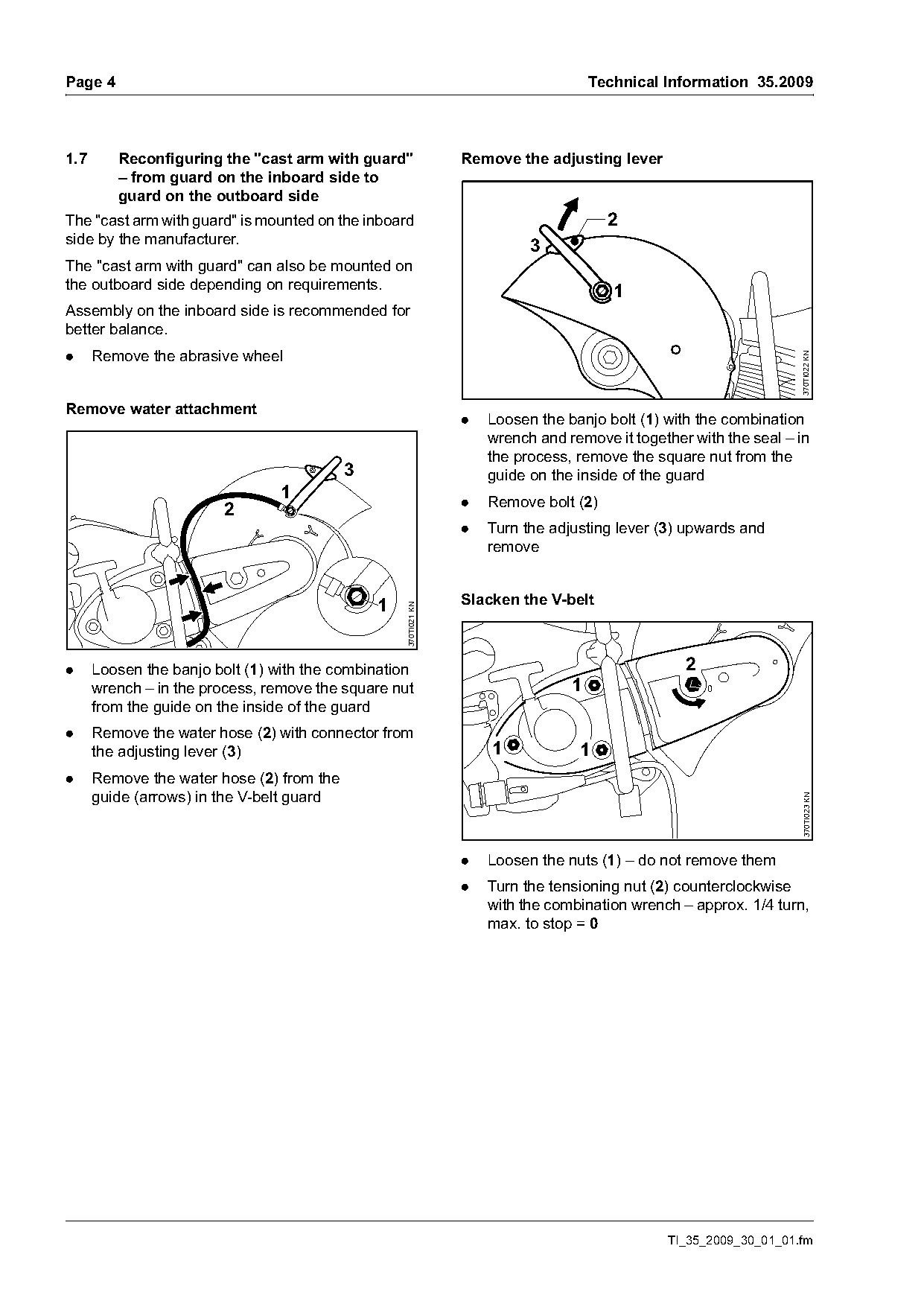
Text of page 4 — search, copy, screen readers
Page 4                                                                               Technical Information 35.2009

1.7      Reconfiguring the "cast arm with guard"                 Remove the adjusting lever
         – from guard on the inboard side to
         guard on the outboard side
The "cast arm with guard" is mounted on the inboard                                    2
side by the manufacturer.                                                  3
The "cast arm with guard" can also be mounted on
the outboard side depending on requirements.                                            1
Assembly on the inboard side is recommended for
better balance.
.     Remove the abrasive wheel

                                                                                                                   370TI022 KN
Remove water attachment
                                                                 .   Loosen the banjo bolt (1) with the combination
                                                                     wrench and remove it together with the seal – in
                                                                     the process, remove the square nut from the
                                           3                         guide on the inside of the guard
                                1                                .   Remove bolt (2)
                        2
                                                                 .   Turn the adjusting lever (3) upwards and
                                                                     remove

                                               1                 Slacken the V-belt
                                                   370TI021 KN

.     Loosen the banjo bolt (1) with the combination                                              2
      wrench – in the process, remove the square nut                             1                    0

      from the guide on the inside of the guard
.     Remove the water hose (2) with connector from
      the adjusting lever (3)                                        1            1
.     Remove the water hose (2) from the
      guide (arrows) in the V-belt guard                                                                           370TI023 KN

                                                                 .   Loosen the nuts (1) – do not remove them
                                                                 .   Turn the tensioning nut (2) counterclockwise
                                                                     with the combination wrench – approx. 1/4 turn,
                                                                     max. to stop = 0

                                                                                               TI_35_2009_30_01_01.fm
Page 5 of 11
Text of page 5 — search, copy, screen readers
Technical Information 35.2009                                                                                     Page 5

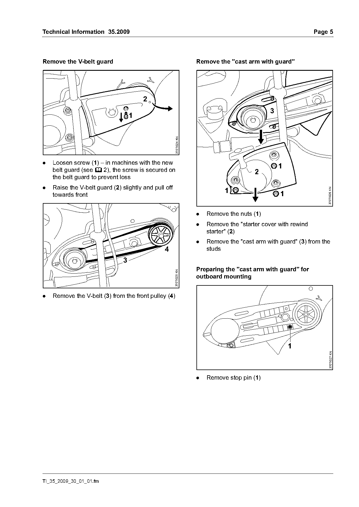
Remove the V-belt guard                                               Remove the "cast arm with guard"

                                        2
                                                                                                 3
                                    1

                                                        370TI024 KN
.   Loosen screw (1) – in machines with the new
    belt guard (see b 2), the screw is secured on
                                                                                                     1
                                                                                           2
    the belt guard to prevent loss
.   Raise the V-belt guard (2) slightly and pull off
                                                                                1

                                                                                                                      370TI026 KN
    towards front                                                                                    1

                                                                      .   Remove the nuts (1)
                                                                      .   Remove the "starter cover with rewind
                                                                          starter" (2)
                                                                      .   Remove the "cast arm with guard" (3) from the
                                                4                         studs
                                3
                                                                      Preparing the "cast arm with guard" for
                                                       370TI025 KN

                                                                      outboard mounting

.   Remove the V-belt (3) from the front pulley (4)

                                                                                                         1
                                                                                                                        370TI027 KN

                                                                      .   Remove stop pin (1)

TI_35_2009_30_01_01.fm
Page 6 of 11
Text of page 6 — search, copy, screen readers
Page 6                                                                                         Technical Information 35.2009

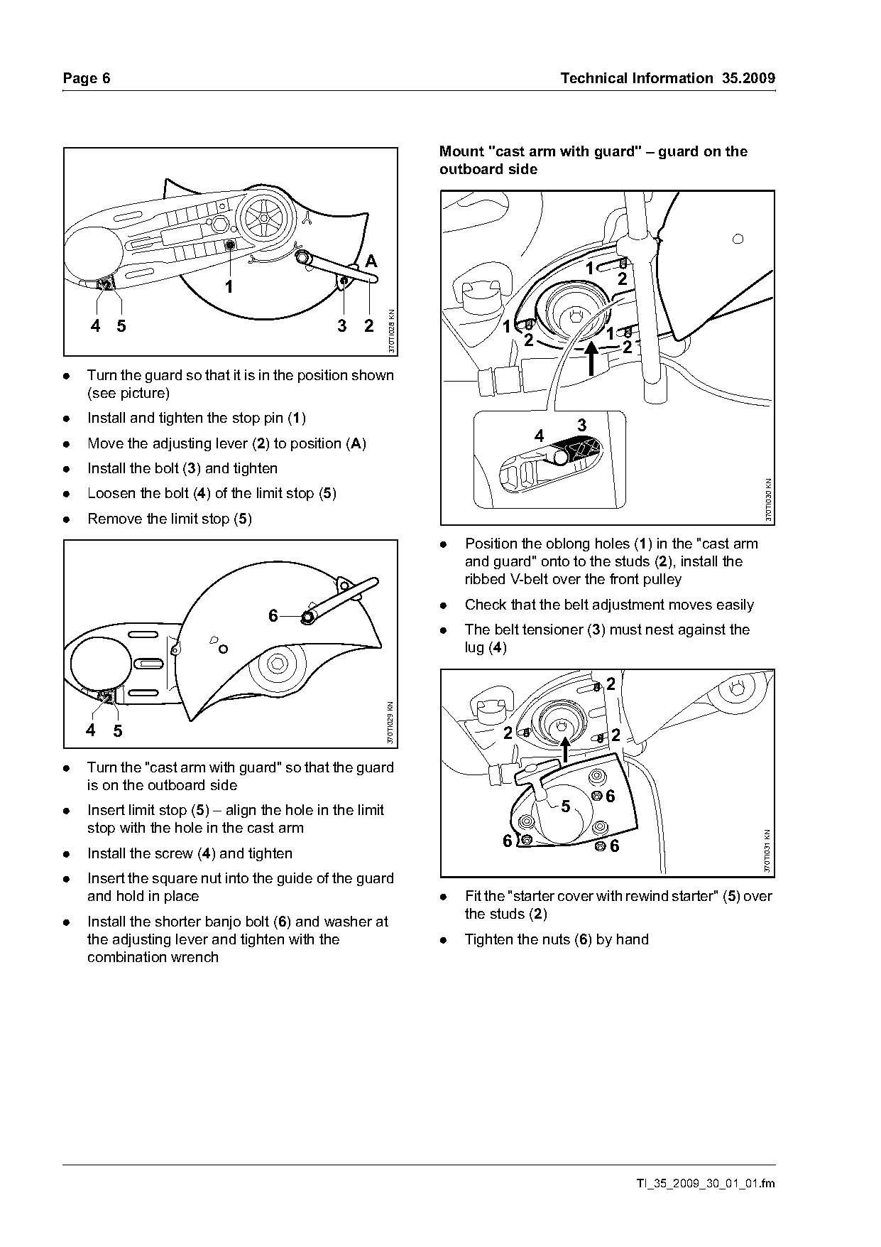
                                                                         Mount "cast arm with guard" – guard on the
                                                                         outboard side

                                                    A                                              1
                           1                                                                               2

                                                           370TI028 KN
    4 5                                         3   2                              1                   1
                                                                                       2                   2
.   Turn the guard so that it is in the position shown
    (see picture)
.   Install and tighten the stop pin (1)
                                                                                                   3
.   Move the adjusting lever (2) to position (A)                                           4
.   Install the bolt (3) and tighten

                                                                                                                                    370TI030 KN
.   Loosen the bolt (4) of the limit stop (5)
.   Remove the limit stop (5)
                                                                         .   Position the oblong holes (1) in the "cast arm
                                                                             and guard" onto to the studs (2), install the
                                                                             ribbed V-belt over the front pulley
                                                                         .   Check that the belt adjustment moves easily
                                   6
                                                                         .   The belt tensioner (3) must nest against the
                                                                             lug (4)

                                                                                                       2
                                                          370TI029 KN

    4 5                                                                            2                   2
.   Turn the "cast arm with guard" so that the guard
    is on the outboard side
                                                                                                       6
.   Insert limit stop (5) – align the hole in the limit                                        5
    stop with the hole in the cast arm
                                                                                                                                   370TI031 KN

                                                                                   6                   6
.   Install the screw (4) and tighten
.   Insert the square nut into the guide of the guard
    and hold in place                                                    .   Fit the "starter cover with rewind starter" (5) over
.   Install the shorter banjo bolt (6) and washer at                         the studs (2)
    the adjusting lever and tighten with the                             .   Tighten the nuts (6) by hand
    combination wrench

                                                                                                               TI_35_2009_30_01_01.fm
Page 7 of 11
Text of page 7 — search, copy, screen readers
Technical Information 35.2009                                                                                  Page 7

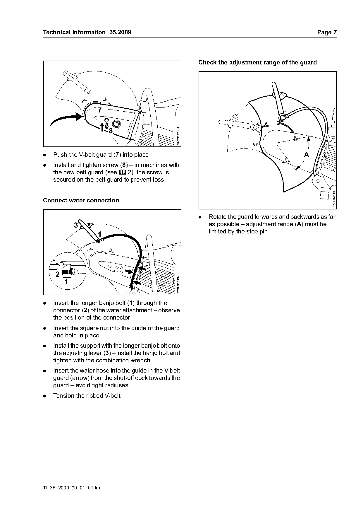
                                                                    Check the adjustment range of the guard


                                                      370TI032 KN
.   Push the V-belt guard (7) into place                                                                  A
.   Install and tighten screw (8) – in machines with
    the new belt guard (see b 2), the screw is
    secured on the belt guard to prevent loss

                                                                                                                    370TI034 KN
Connect water connection

                                                                    .   Rotate the guard forwards and backwards as far
            3                                                           as possible – adjustment range (A) must be
                                                                        limited by the stop pin
                      1

    2
                                                      370TI033 KN


.   Insert the longer banjo bolt (1) through the
    connector (2) of the water attachment – observe
    the position of the connector
.   Insert the square nut into the guide of the guard
    and hold in place
.   Install the support with the longer banjo bolt onto
    the adjusting lever (3) – install the banjo bolt and
    tighten with the combination wrench
.   Insert the water hose into the guide in the V-belt
    guard (arrow) from the shut-off cock towards the
    guard – avoid tight radiuses
.   Tension the ribbed V-belt

TI_35_2009_30_01_01.fm
Page 8 of 11
Text of page 8 — search, copy, screen readers
Page 8                                                                                        Technical Information 35.2009

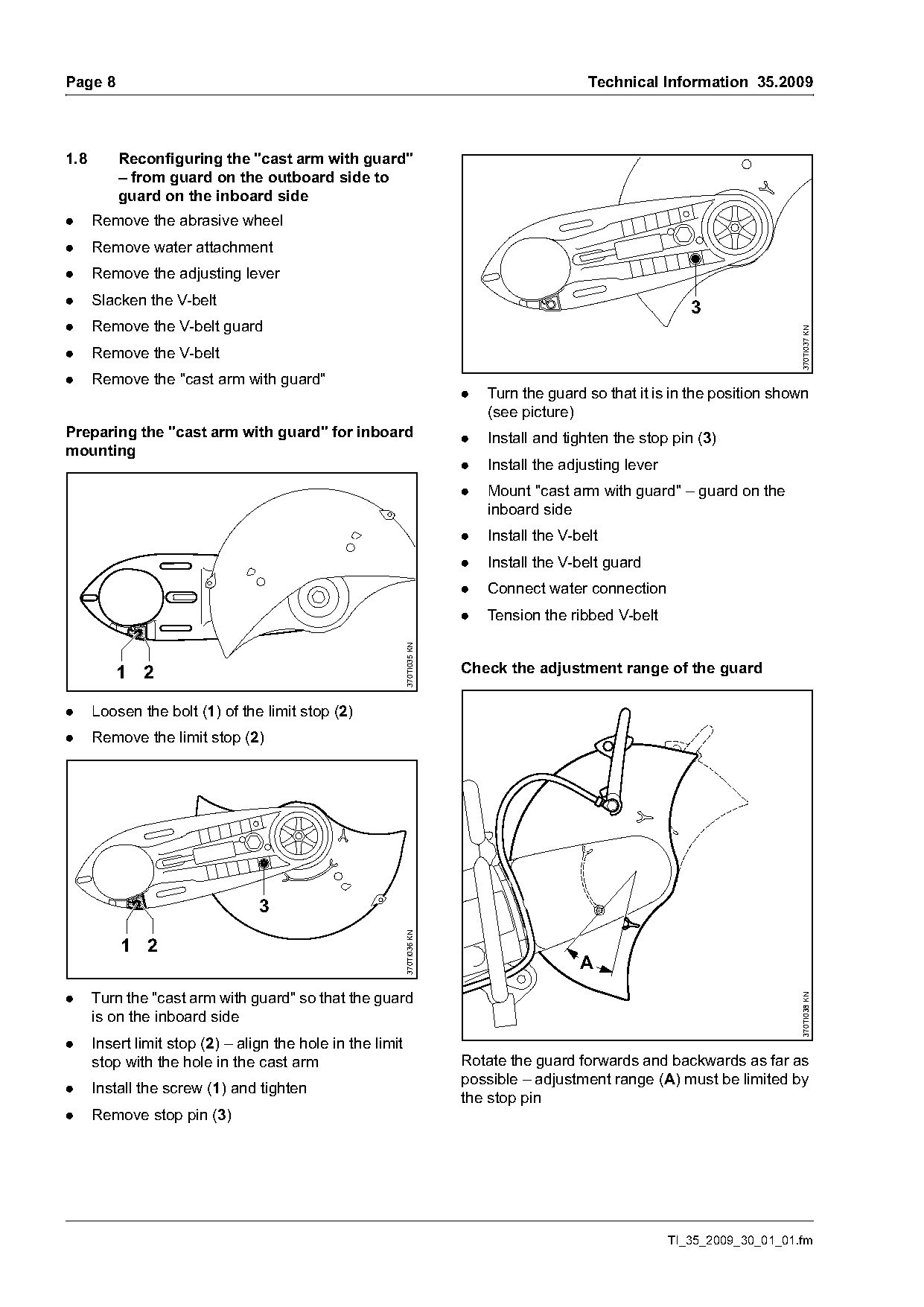
1.8       Reconfiguring the "cast arm with guard"
          – from guard on the outboard side to
          guard on the inboard side
.     Remove the abrasive wheel
.     Remove water attachment
.     Remove the adjusting lever
.     Slacken the V-belt
                                                                                                               3
.     Remove the V-belt guard

                                                                                                                                370TI037 KN
.     Remove the V-belt
.     Remove the "cast arm with guard"
                                                                          .   Turn the guard so that it is in the position shown
                                                                              (see picture)
Preparing the "cast arm with guard" for inboard                           .   Install and tighten the stop pin (3)
mounting
                                                                          .   Install the adjusting lever
                                                                          .   Mount "cast arm with guard" – guard on the
                                                                              inboard side
                                                                          .   Install the V-belt
                                                                          .   Install the V-belt guard
                                                                          .   Connect water connection
                                                                          .   Tension the ribbed V-belt
                                                            370TI035 KN

         1 2                                                              Check the adjustment range of the guard

.     Loosen the bolt (1) of the limit stop (2)
.     Remove the limit stop (2)

                                 3
                                                            370TI036 KN

          1 2
                                                                                             A
.     Turn the "cast arm with guard" so that the guard
                                                                                                                                370TI038 KN

      is on the inboard side
.     Insert limit stop (2) – align the hole in the limit
      stop with the hole in the cast arm                                  Rotate the guard forwards and backwards as far as
                                                                          possible – adjustment range (A) must be limited by
.     Install the screw (1) and tighten
                                                                          the stop pin
.     Remove stop pin (3)

                                                                                                            TI_35_2009_30_01_01.fm
Page 9 of 11
Text of page 9 — search, copy, screen readers
Technical Information 35.2009                                                                                Page 9

2.       Belt guard, screw                                         Spare parts
                                                                   The previous versions of the belt guard
                 1, 2                    3, 4                      4238 700 8101 (TS 410) and the belt guard
         7                                                         4238 700 8100 (TS 420) are no longer available.
                                                                   The new versions of belt guard 4238 700 8107
                                                                   (TS 410) and belt guard 4238 700 8109 (TS 420)
                                                                   can also be used for older machines. The previous
                                                                   versions of spline screw IS-M5x30x22-10.9
                                                                   (9022 341 1070) and hollow rivet
                                                                   DIN7339-7.5x1x6.8 (9443 825 7130) remain
                     6                   5                         available for older machines.

                                                    3701TI072 KN
Left:        Previous versions of the belt guard
             and the screw
Right:       New versions of the belt guard and
             the screw
The previous versions of the belt guard (1)
4238 700 8101 (TS 410) and the belt guard (2)
4238 700 8100 (TS 420) are being replaced by the
new versions of the belt guard (3) 4238 700 8107
(TS 410) and the belt guard (4) 4238 700 8109
(TS 420).
The new versions of the belt guard (3, 4) are
fastened to the cast arm with the new screw
IS-M5x21 (5) (9022 319 1027). In the versions of
the belt guard (3, 4), the new screw IS-M5x21 (5)
(9022 319 1027) is secured against loss. The
previous versions of the spline screw
IS-M5x30x22-10.9 (6) (9022 341 1070) and the
hollow rivet DIN7339-7.5x1x6.8 (7)
(9443 825 7130) are no longer needed.

Tightening torques
Belt guard / cast arm                 6 Nm

TI_35_2009_30_01_01.fm
Page 10 of 11
Text of page 10 — search, copy, screen readers
Page 10                                                                                    Technical Information 35.2009

3.       Set of instruction labels                                   3.2      Set of instruction labels 0000 960 0101
                                                                              (only for TS 420)

                                                                              1   2                      3
3.1      Set of instruction labels 0000 960 0100
         (only for TS 410)

         1   2                      3

                                                                                                                           3701TI073 KN
                                                                     Left:            Previous versions of the instruction
                                                      3701TI073 KN

                                                                                      labels
                                                                     Right:           New versions of the instruction labels
Left:            Previous versions of the instruction                TS 420 only, the previous versions of instruction
                 labels                                              label (1) 0000 967 3521 and instruction label (2)
Right:           New versions of the instruction labels              0000 967 3520 are being replaced by the new "set
                                                                     of instruction labels" (3) 0000 960 0101.
TS 410 only, the previous versions of instruction
label (1) 0000 967 3521 and instruction label (2)
0000 967 3511 are being replaced by the new "set                     Spare parts/service notes
of instruction labels" (3) 0000 960 0100.
                                                                     The previous versions of instruction label (1)
                                                                     0000 967 3521 and instruction label (2)
Spare parts/service notes                                            0000 967 3520 are no longer available. The new
                                                                     "set of instruction labels" (3) 0000 960 0101 can
The previous versions of instruction label (1)
                                                                     also be used with older STIHL Cutquik® TS 420 cut-
0000 967 3521 and instruction label (2)
                                                                     off machines.
0000 967 3511 are no longer available. The new
"set of instruction labels" (3) 0000 960 0100 can                    Always attach both instruction labels in the new "set
also be used with older STIHL Cutquik® TS 410 cut-                   of instruction labels" (3) 0000 960 0101.
off machines.
Always attach both instruction labels in the new "set
of instruction labels" (3) 0000 960 0100.

                                                                                                       TI_35_2009_30_01_01.fm
Page 11 of 11
Text of page 11 — search, copy, screen readers
Technical Information 35.2009                                                                        Page 11

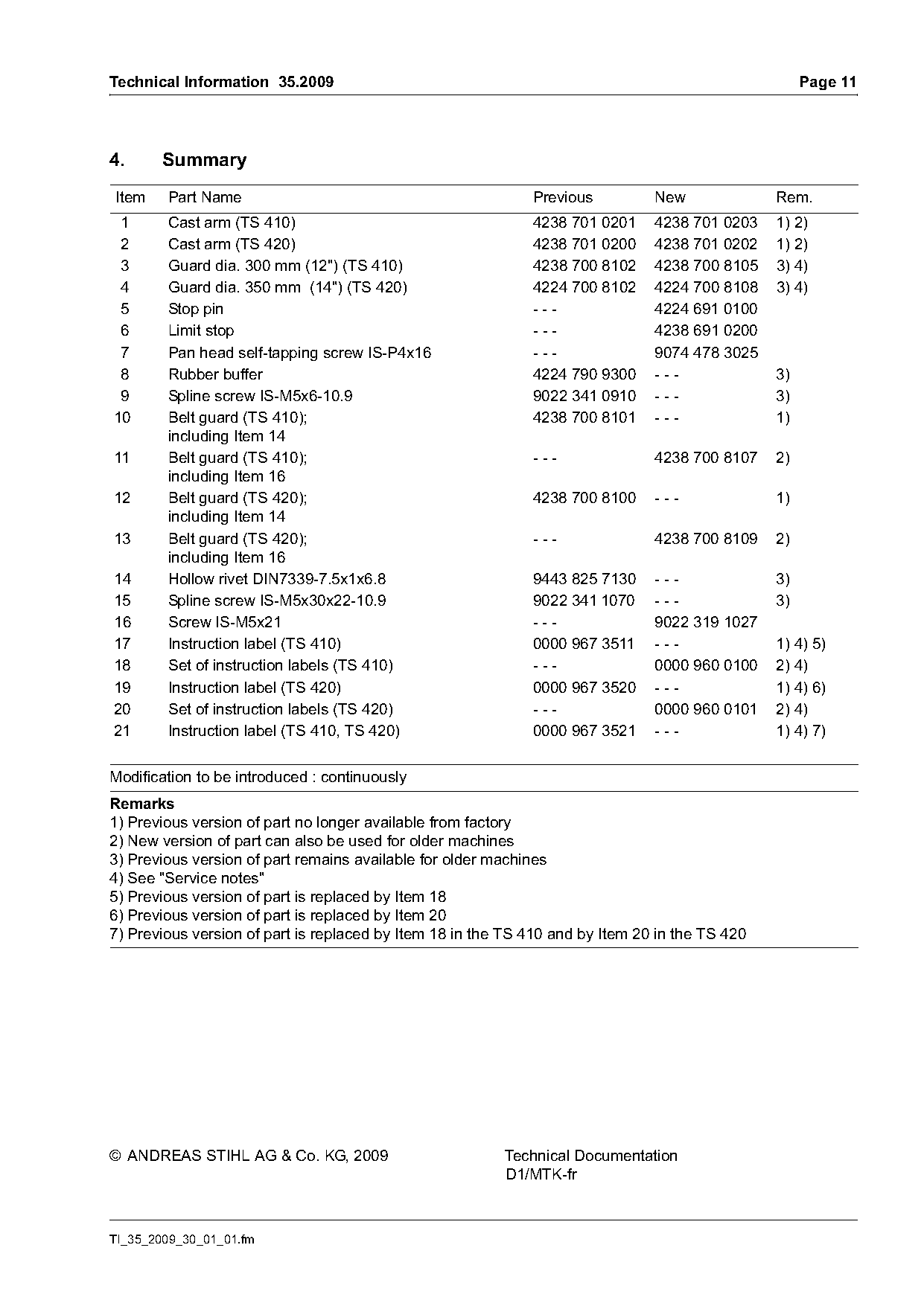
4.     Summary
Item    Part Name                                            Previous          New              Rem.
 1      Cast arm (TS 410)                                    4238 701 0201     4238 701 0203    1) 2)
 2      Cast arm (TS 420)                                    4238 701 0200     4238 701 0202    1) 2)
 3      Guard dia. 300 mm (12") (TS 410)                     4238 700 8102     4238 700 8105    3) 4)
 4      Guard dia. 350 mm (14") (TS 420)                     4224 700 8102     4224 700 8108    3) 4)
 5      Stop pin                                             ---               4224 691 0100
 6      Limit stop                                           ---               4238 691 0200
 7      Pan head self-tapping screw IS-P4x16                 ---               9074 478 3025
 8      Rubber buffer                                        4224 790 9300     ---              3)
 9      Spline screw IS-M5x6-10.9                            9022 341 0910     ---              3)
10      Belt guard (TS 410);                                 4238 700 8101     ---              1)
        including Item 14
11      Belt guard (TS 410);                                 ---               4238 700 8107    2)
        including Item 16
12      Belt guard (TS 420);                                 4238 700 8100     ---              1)
        including Item 14
13      Belt guard (TS 420);                                 ---               4238 700 8109    2)
        including Item 16
14      Hollow rivet DIN7339-7.5x1x6.8                       9443 825 7130     ---              3)
15      Spline screw IS-M5x30x22-10.9                        9022 341 1070     ---              3)
16      Screw IS-M5x21                                       ---               9022 319 1027
17      Instruction label (TS 410)                           0000 967 3511     ---              1) 4) 5)
18      Set of instruction labels (TS 410)                   ---               0000 960 0100    2) 4)
19      Instruction label (TS 420)                           0000 967 3520     ---              1) 4) 6)
20      Set of instruction labels (TS 420)                   ---               0000 960 0101    2) 4)
21      Instruction label (TS 410, TS 420)                   0000 967 3521     ---              1) 4) 7)

Modification to be introduced : continuously
Remarks
1) Previous version of part no longer available from factory
2) New version of part can also be used for older machines
3) Previous version of part remains available for older machines
4) See "Service notes"
5) Previous version of part is replaced by Item 18
6) Previous version of part is replaced by Item 20
7) Previous version of part is replaced by Item 18 in the TS 410 and by Item 20 in the TS 420

© ANDREAS STIHL AG & Co. KG, 2009                        Technical Documentation
                                                         D1/MTK-fr

TI_35_2009_30_01_01.fm
Most of these PDFs embed fonts with a shifted character map, so the text above was recovered rather than copied — read it as a faithful but imperfect transcription, and treat the page image above each block as the authority where the two disagree — the figures exist only there, because they are vector drawings that text extraction cannot keep.