Technical Information · issue 36 of 2009
Technical Description; Specifications; Cutting Attachments; Special Accessories; Servicing Accessories; Spare Parts; Repairs
IssueTI 36/2009
Full text
Page 1 of 8
Text of page 1 — search, copy, screen readers
STIH)

Technical Information                                   36.2009

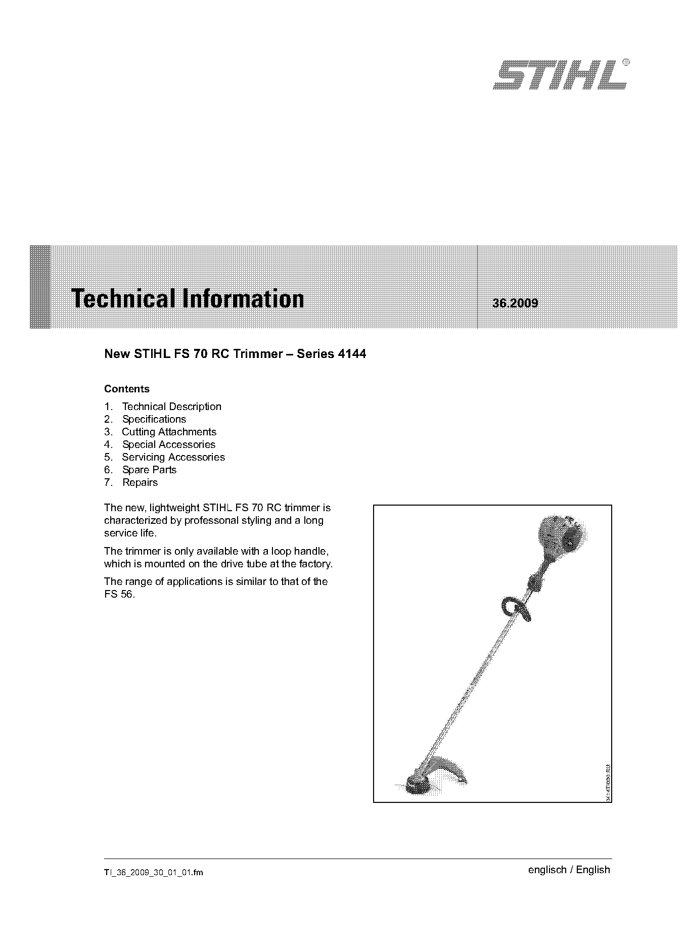
  New STIHL FS 70 RC Trimmer – Series 4144

  Contents
  1.   Technical Description
  2.   Specifications
  3.   Cutting Attachments
  4.   Special Accessories
  5.   Servicing Accessories
  6.   Spare Parts
  7.   Repairs

  The new, lightweight STIHL FS 70 RC trimmer is
  characterized by professonal styling and a long
  service life.
  The trimmer is only available with a loop handle,
  which is mounted on the drive tube at the factory.
  The range of applications is similar to that of the
  FS 56.

  TI_36_2009_30_01_01.fm                                     englisch / English
Page 2 of 8
Text of page 2 — search, copy, screen readers
Page 2                                                                                Technical Information 36.2009

1.       Technical Description                                    1.3     Engine, carburetor
                                                                  The FS 70 RC engine with stratified scavenging and
1.1      Function of stop switch and the ignition                 carburetor with baffle plate are the same as those in
                                                                  the FS 56.
                                                                  See TI 23.2008 for further information on the engine
                                  1                               and carburetor.

                                                                  1.4     Shroud

                                                    546TI000 KN

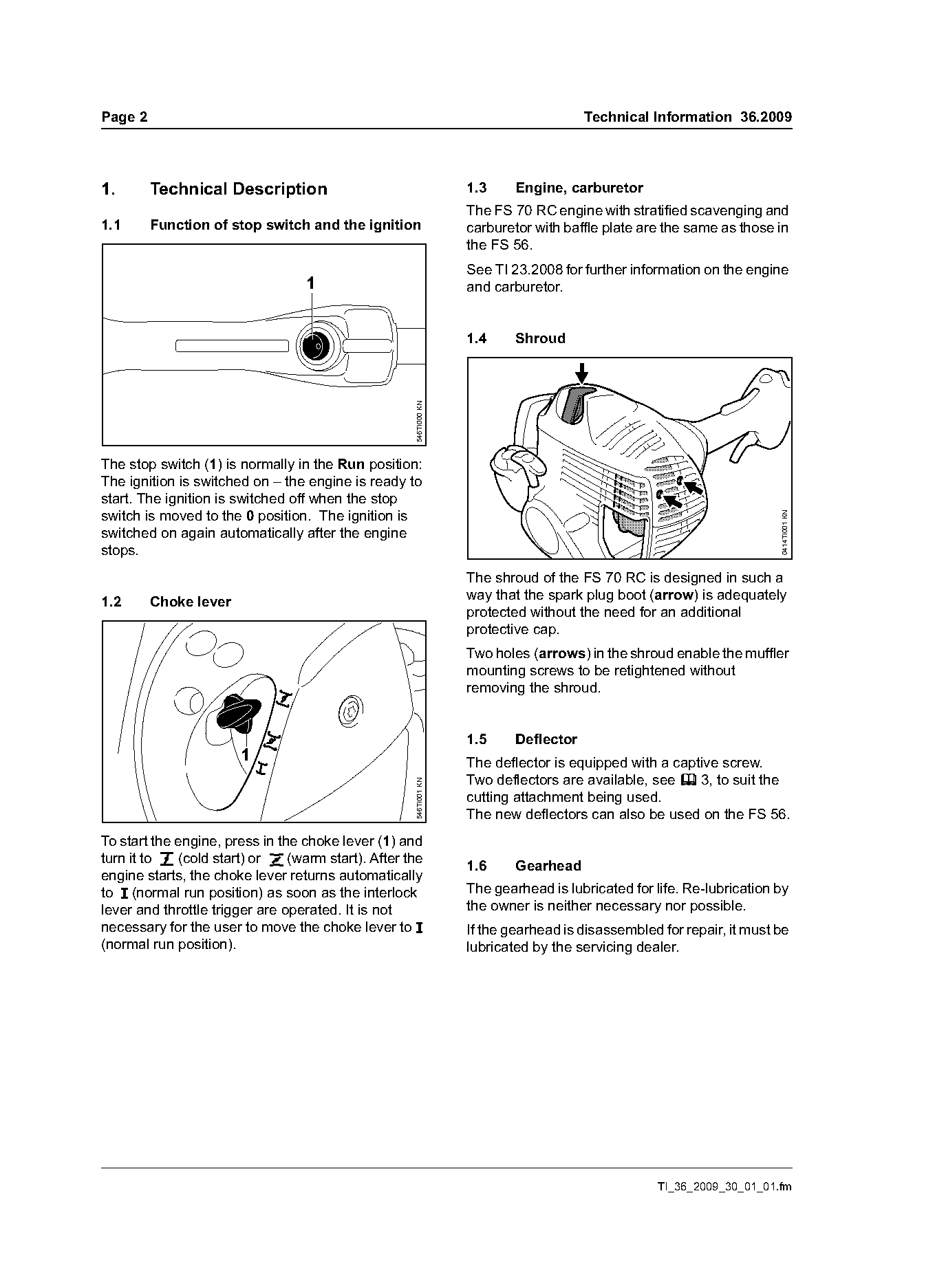
The stop switch (1) is normally in the Run position:
The ignition is switched on – the engine is ready to
start. The ignition is switched off when the stop
switch is moved to the 0 position. The ignition is

                                                                                                                      0414TI001 KN
switched on again automatically after the engine
stops.
                                                                  The shroud of the FS 70 RC is designed in such a
1.2      Choke lever                                              way that the spark plug boot (arrow) is adequately
                                                                  protected without the need for an additional
                                                                  protective cap.
                                                                  Two holes (arrows) in the shroud enable the muffler
                                                                  mounting screws to be retightened without
                                                                  removing the shroud.

                                                                  1.5     Deflector
                       1                                          The deflector is equipped with a captive screw.
                                                                  Two deflectors are available, see b 3, to suit the
                                                    546TI001 KN

                                                                  cutting attachment being used.
                                                                  The new deflectors can also be used on the FS 56.
To start the engine, press in the choke lever (1) and
turn it to g (cold start) or < (warm start). After the            1.6     Gearhead
engine starts, the choke lever returns automatically
to F (normal run position) as soon as the interlock               The gearhead is lubricated for life. Re-lubrication by
lever and throttle trigger are operated. It is not                the owner is neither necessary nor possible.
necessary for the user to move the choke lever to F               If the gearhead is disassembled for repair, it must be
(normal run position).                                            lubricated by the servicing dealer.

                                                                                                  TI_36_2009_30_01_01.fm
Page 3 of 8
Text of page 3 — search, copy, screen readers
Technical Information 36.2009                                                                                Page 3

2.      Specifications

2.1     Engine

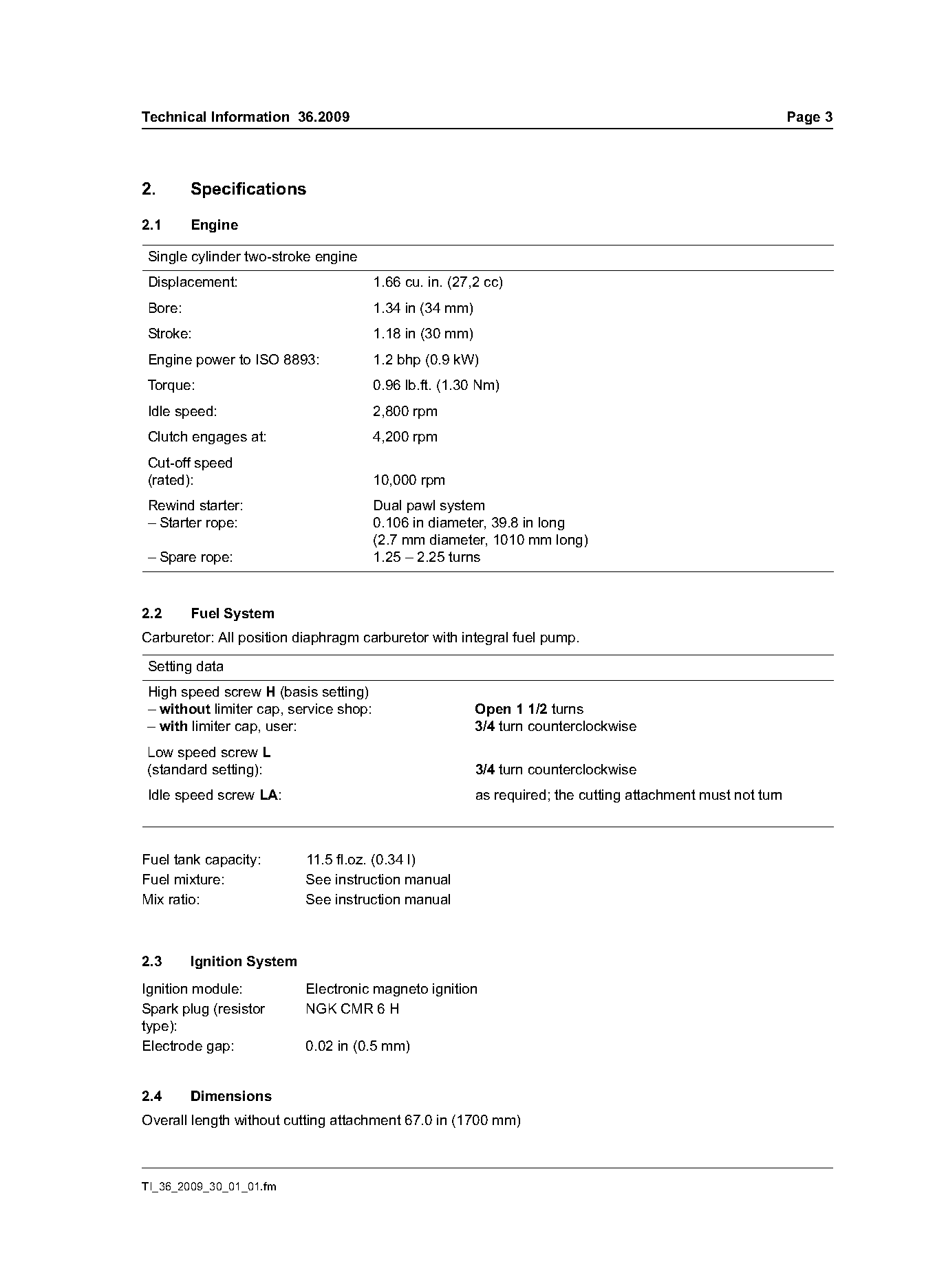
Single cylinder two-stroke engine
Displacement:                          1.66 cu. in. (27,2 cc)
Bore:                                  1.34 in (34 mm)
Stroke:                                1.18 in (30 mm)
Engine power to ISO 8893:              1.2 bhp (0.9 kW)
Torque:                                0.96 lb.ft. (1.30 Nm)
Idle speed:                            2,800 rpm
Clutch engages at:                     4,200 rpm
Cut-off speed
(rated):                               10,000 rpm
Rewind starter:                        Dual pawl system
– Starter rope:                        0.106 in diameter, 39.8 in long
                                       (2.7 mm diameter, 1010 mm long)
– Spare rope:                          1.25 – 2.25 turns

2.2     Fuel System
Carburetor: All position diaphragm carburetor with integral fuel pump.

Setting data
High speed screw H (basis setting)
– without limiter cap, service shop:                     Open 1 1/2 turns
– with limiter cap, user:                                3/4 turn counterclockwise
Low speed screw L
(standard setting):                                      3/4 turn counterclockwise
Idle speed screw LA:                                     as required; the cutting attachment must not turn

Fuel tank capacity:       11.5 fl.oz. (0.34 l)
Fuel mixture:             See instruction manual
Mix ratio:                See instruction manual

2.3     Ignition System
Ignition module:          Electronic magneto ignition
Spark plug (resistor      NGK CMR 6 H
type):
Electrode gap:            0.02 in (0.5 mm)

2.4     Dimensions
Overall length without cutting attachment 67.0 in (1700 mm)

TI_36_2009_30_01_01.fm
Page 4 of 8
Text of page 4 — search, copy, screen readers
Page 4                                                          Technical Information 36.2009

2.5      Weight
Without cutting attachment and deflector
FS 70 RC:                         10.6 lbs (4.8 kg)

3.       Cutting Attachments
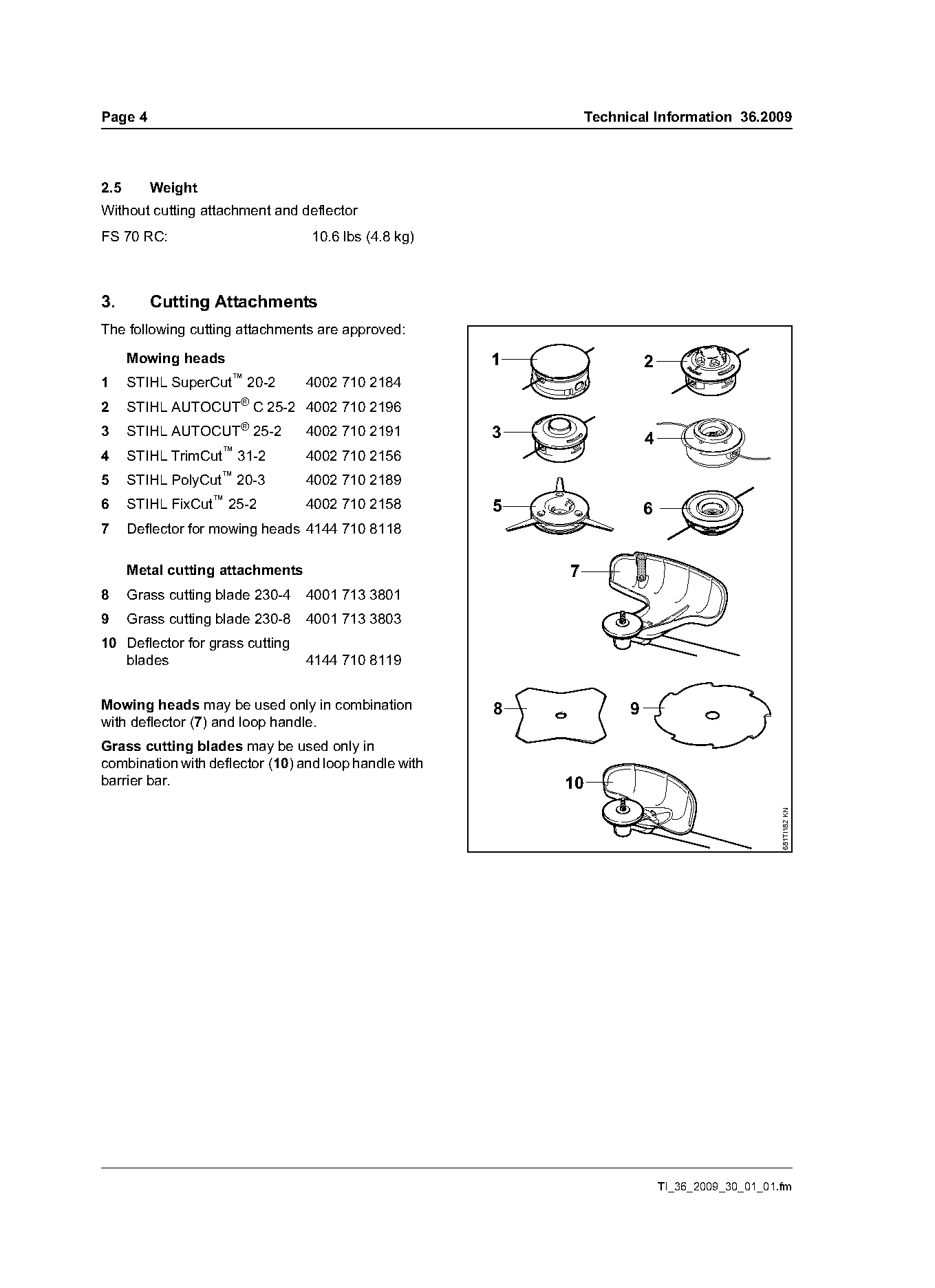
The following cutting attachments are approved:

      Mowing heads                                     1                  2
                      ™
1     STIHL SuperCut      20-2    4002 710 2184
2     STIHL AUTOCUT® C 25-2 4002 710 2196
3     STIHL AUTOCUT® 25-2         4002 710 2191        3                  4
                    ™
4     STIHL TrimCut     31-2      4002 710 2156
5     STIHL PolyCut™ 20-3         4002 710 2189
6     STIHL FixCut™ 25-2          4002 710 2158        5                  6
7     Deflector for mowing heads 4144 710 8118

      Metal cutting attachments                            7
8     Grass cutting blade 230-4   4001 713 3801
9     Grass cutting blade 230-8   4001 713 3803
10 Deflector for grass cutting
   blades                         4144 710 8119

Mowing heads may be used only in combination           8              9
with deflector (7) and loop handle.
Grass cutting blades may be used only in
combination with deflector (10) and loop handle with
barrier bar.                                               10                                     681TI182 KN

                                                                              TI_36_2009_30_01_01.fm
Page 5 of 8
Text of page 5 — search, copy, screen readers
Technical Information 36.2009                                                           Page 5

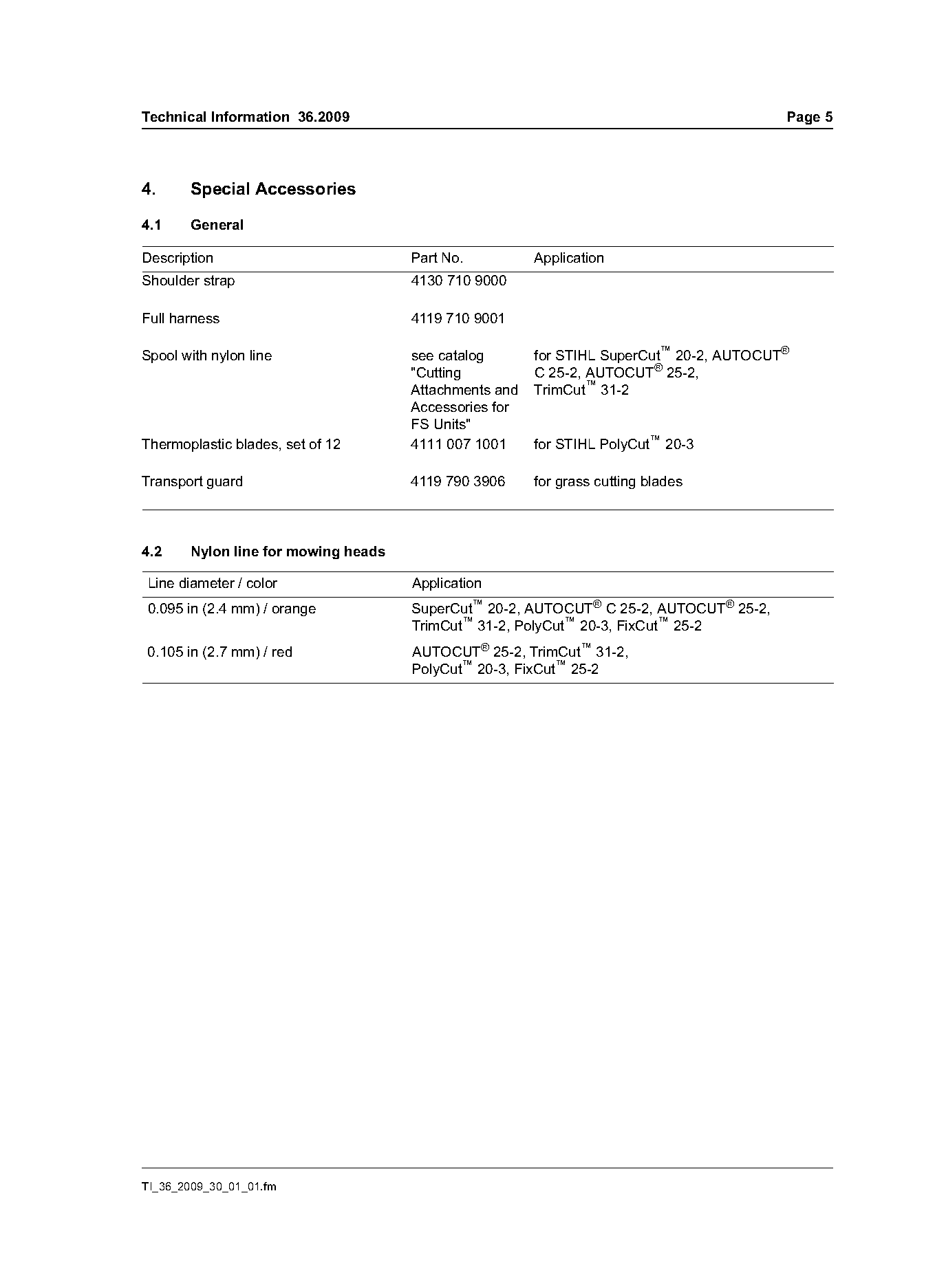
4.     Special Accessories

4.1    General

Description                          Part No.          Application
Shoulder strap                       4130 710 9000

Full harness                         4119 710 9001

Spool with nylon line                see catalog       for STIHL SuperCut™ 20-2, AUTOCUT®
                                     "Cutting          C 25-2, AUTOCUT® 25-2,
                                     Attachments and   TrimCut™ 31-2
                                     Accessories for
                                     FS Units"
Thermoplastic blades, set of 12      4111 007 1001     for STIHL PolyCut™ 20-3

Transport guard                      4119 790 3906     for grass cutting blades

4.2    Nylon line for mowing heads

Line diameter / color                Application
0.095 in (2.4 mm) / orange           SuperCut™ 20-2, AUTOCUT® C 25-2, AUTOCUT® 25-2,
                                     TrimCut™ 31-2, PolyCut™ 20-3, FixCut™ 25-2
0.105 in (2.7 mm) / red              AUTOCUT® 25-2, TrimCut™ 31-2,
                                     PolyCut™ 20-3, FixCut™ 25-2

TI_36_2009_30_01_01.fm
Page 6 of 8
Text of page 6 — search, copy, screen readers
Page 6                                                                     Technical Information 36.2009

5.       Servicing Accessories

5.1      Special servicing tools
Special servicing tools are listed in the STIHL Series
4144 Powerhead, STIHL Series 4144 Components
and STIHL KombiTools shop manuals.
No new or additional special tools are required for
the FS 70 RC.

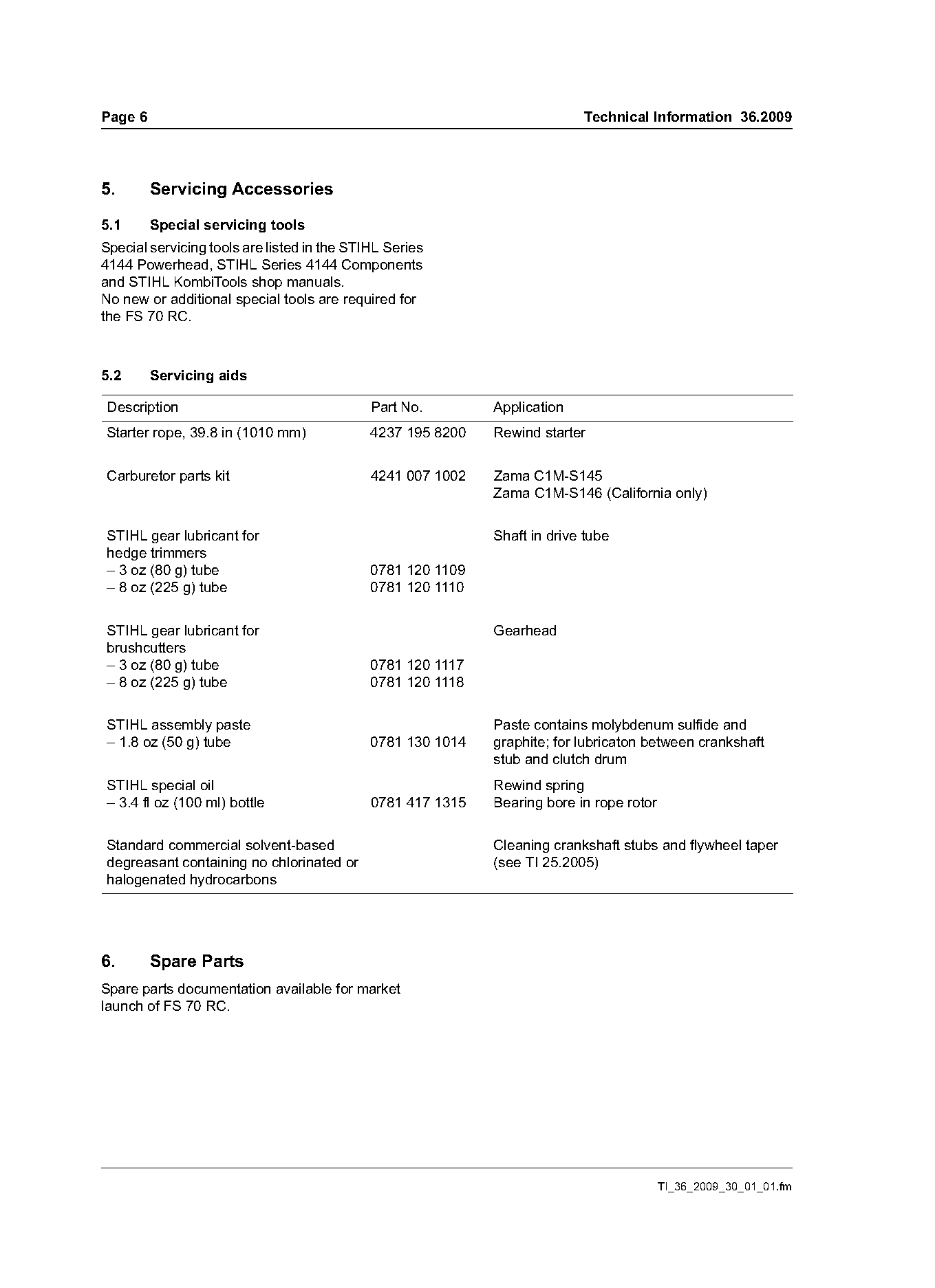
5.2      Servicing aids

Description                                  Part No.        Application
Starter rope, 39.8 in (1010 mm)              4237 195 8200   Rewind starter

Carburetor parts kit                         4241 007 1002   Zama C1M-S145
                                                             Zama C1M-S146 (California only)

STIHL gear lubricant for                                     Shaft in drive tube
hedge trimmers
– 3 oz (80 g) tube                           0781 120 1109
– 8 oz (225 g) tube                          0781 120 1110

STIHL gear lubricant for                                     Gearhead
brushcutters
– 3 oz (80 g) tube                           0781 120 1117
– 8 oz (225 g) tube                          0781 120 1118

STIHL assembly paste                                         Paste contains molybdenum sulfide and
– 1.8 oz (50 g) tube                         0781 130 1014   graphite; for lubricaton between crankshaft
                                                             stub and clutch drum
STIHL special oil                                            Rewind spring
– 3.4 fl oz (100 ml) bottle                  0781 417 1315   Bearing bore in rope rotor

Standard commercial solvent-based                            Cleaning crankshaft stubs and flywheel taper
degreasant containing no chlorinated or                      (see TI 25.2005)
halogenated hydrocarbons

6.       Spare Parts
Spare parts documentation available for market
launch of FS 70 RC.

                                                                                          TI_36_2009_30_01_01.fm
Page 7 of 8
Text of page 7 — search, copy, screen readers
Technical Information 36.2009                                                                            Page 7

7.       Repairs
If the machine is started in the course of repairs, it is
essential to observe all country-specific safety
regulations and the safety precautions in the
instruction manual.

7.1      Service manuals
The following service manuals can be used for
repair procedures on the FS 70 RC:

           For the engine, controls and drive tube                                      For the gearhead
            of the FS 70 RC (4144 powerhead)                                            of the FS 70 RC

         Service manual                 Service manual                                   Service manual
     Series 4144 Powerhead         Series 4144 Components                                 KombiTools
          0455 938 0123                 0455 545 0123                                    0455 227 0123

7.2      Tightening torques                                 7.4    Serial number
The tightening torques are also listed in the above
service manuals.
Also see chapter b 7.5.4

7.3      Starting after a long period of storage
Problems with starting may be experienced if the
machine is stored for several months at
temperatures below 41 °F (5 °C).

                                                                                                              0414TI002 KN
In such a case, press the manual fuel pump several
times to prime the carburetor. Then wait a few
minutes before attempting to start the engine.
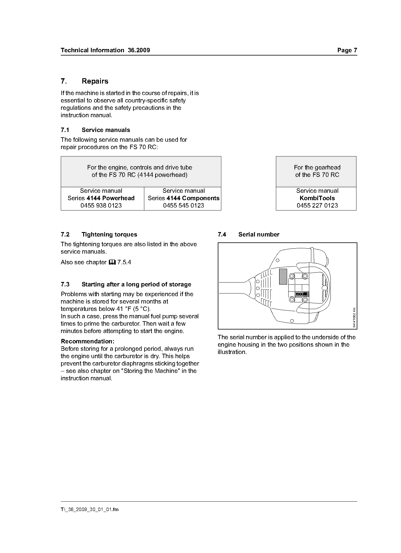
                                                            The serial number is applied to the underside of the
Recommendation:
                                                            engine housing in the two positions shown in the
Before storing for a prolonged period, always run
                                                            illustration.
the engine until the carburetor is dry. This helps
prevent the carburetor diaphragms sticking together
– see also chapter on "Storing the Machine" in the
instruction manual.

TI_36_2009_30_01_01.fm
Page 8 of 8
Text of page 8 — search, copy, screen readers
Page 8                                                                                Technical Information 36.2009

7.5      Service Notes                                             Note on OH 723 press fluid
                                                                   OH 723 press fluid produces a lubricating film which
7.5.1    Hose barb connectors on carburetor
                                                                   simplifies assembly. The lubricant evaporates after
                                                                   a short period – the hose is then tight.
                                                                   Never use fuel, oil or grease as a lubricant for this
                                                                   purpose. Fuel, oil and grease do not evaporate – the
                                                                   hose may loosen or become detached.

                                                                   7.5.2   Piston
                                                                   The piston has two piston rings.

                                                                   7.5.3   Gearhead
                                                     546TI009 KN   The FS 70 RC gearhead has two ball bearings as
                                                                   opposed to the single ball bearing in the FS 56
                                                                   gearhead.
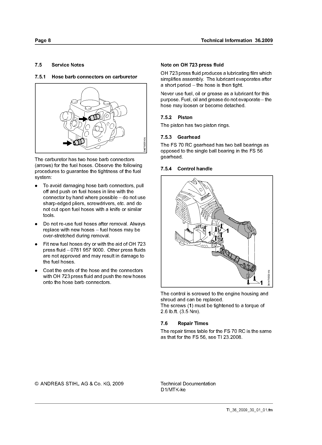
The carburetor has two hose barb connectors
(arrows) for the fuel hoses. Observe the following
                                                                   7.5.4   Control handle
procedures to guarantee the tightness of the fuel
system:
.     To avoid damaging hose barb connectors, pull
      off and push on fuel hoses in line with the
      connector by hand where possible – do not use
      sharp-edged pliers, screwdrivers, etc. and do
      not cut open fuel hoses with a knife or similar
      tools.
.     Do not re-use fuel hoses after removal. Always
      replace with new hoses – fuel hoses may be                                                  1
      over-stretched during removal.                                                     1
.     Fit new fuel hoses dry or with the aid of OH 723
      press fluid – 0781 957 9000. Other press fluids
      are not approved and may result in damage to
      the fuel hoses.
.     Coat the ends of the hose and the connectors                                                                    0414TI003 KN

      with OH 723 press fluid and push the new hoses
      onto the hose barb connectors.                                                                              1
                                                                   The control is screwed to the engine housing and
                                                                   shroud and can be replaced.
                                                                   The screws (1) must be tightened to a torque of
                                                                   2.6 lb.ft. (3.5 Nm).

                                                                   7.6     Repair Times
                                                                   The repair times table for the FS 70 RC is the same
                                                                   as that for the FS 56, see TI 23.2008.

© ANDREAS STIHL AG & Co. KG, 2009                                  Technical Documentation
                                                                   D1/MTK-ke

                                                                                                  TI_36_2009_30_01_01.fm
Most of these PDFs embed fonts with a shifted character map, so the text above was recovered rather than copied — read it as a faithful but imperfect transcription, and treat the page image above each block as the authority where the two disagree — the figures exist only there, because they are vector drawings that text extraction cannot keep.