Technical Information · issue 43 of 2009
New vacuum STIHL SE 61
IssueTI 43/2009
Full text
Page 1 of 6
Text of page 1 — search, copy, screen readers
STIH)

Technical Information                                                           43.2009

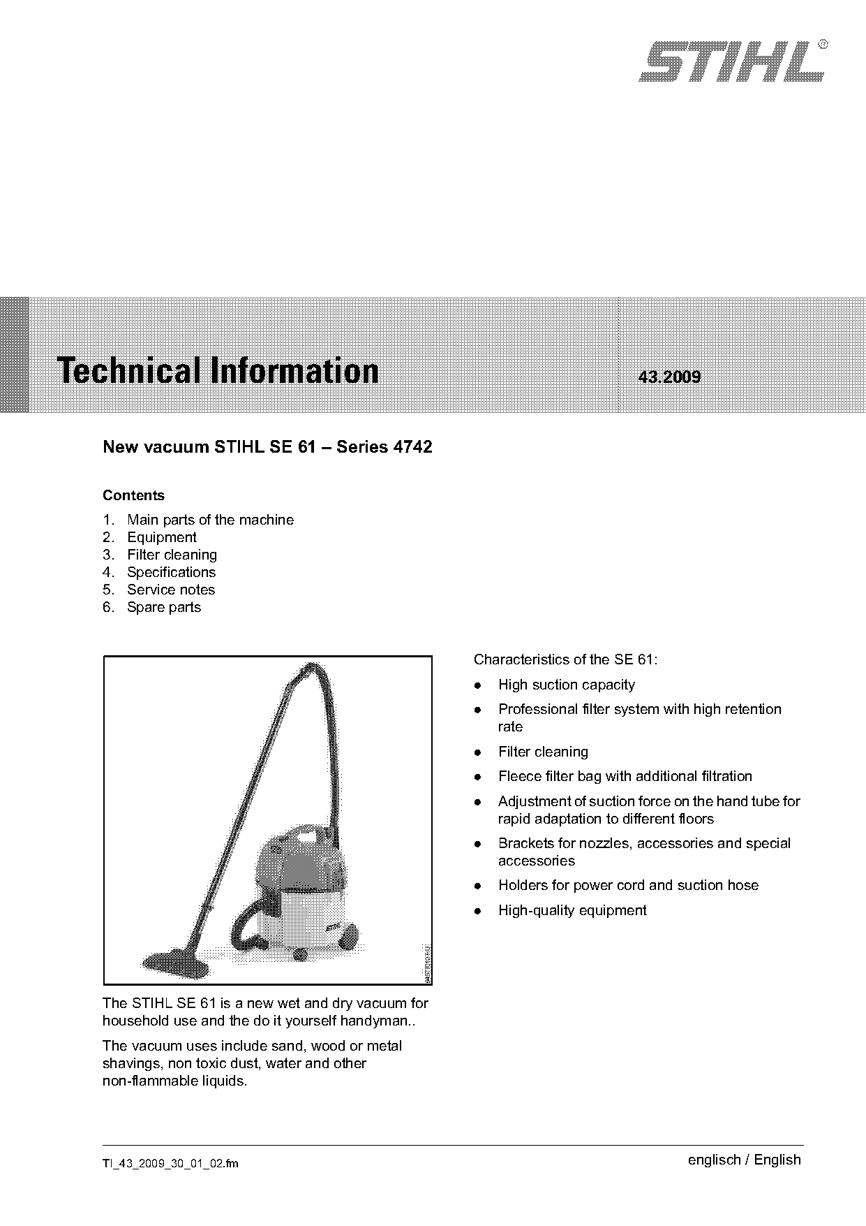
  New vacuum STIHL SE 61 – Series 4742

  Contents
  1.   Main parts of the machine
  2.   Equipment
  3.   Filter cleaning
  4.   Specifications
  5.   Service notes
  6.   Spare parts

                                                    Characteristics of the SE 61:
                                                    .   High suction capacity
                                                    .   Professional filter system with high retention
                                                        rate
                                                    .   Filter cleaning
                                                    .   Fleece filter bag with additional filtration
                                                    .   Adjustment of suction force on the hand tube for
                                                        rapid adaptation to different floors
                                                    .   Brackets for nozzles, accessories and special
                                                        accessories
                                                    .   Holders for power cord and suction hose
                                                    .   High-quality equipment

  The STIHL SE 61 is a new wet and dry vacuum for
  household use and the do it yourself handyman..
  The vacuum uses include sand, wood or metal
  shavings, non toxic dust, water and other
  non-flammable liquids.

  TI_43_2009_30_01_02.fm                                                                englisch / English
Page 2 of 6
Text of page 2 — search, copy, screen readers
Page 2                                                                        Technical Information 43.2009

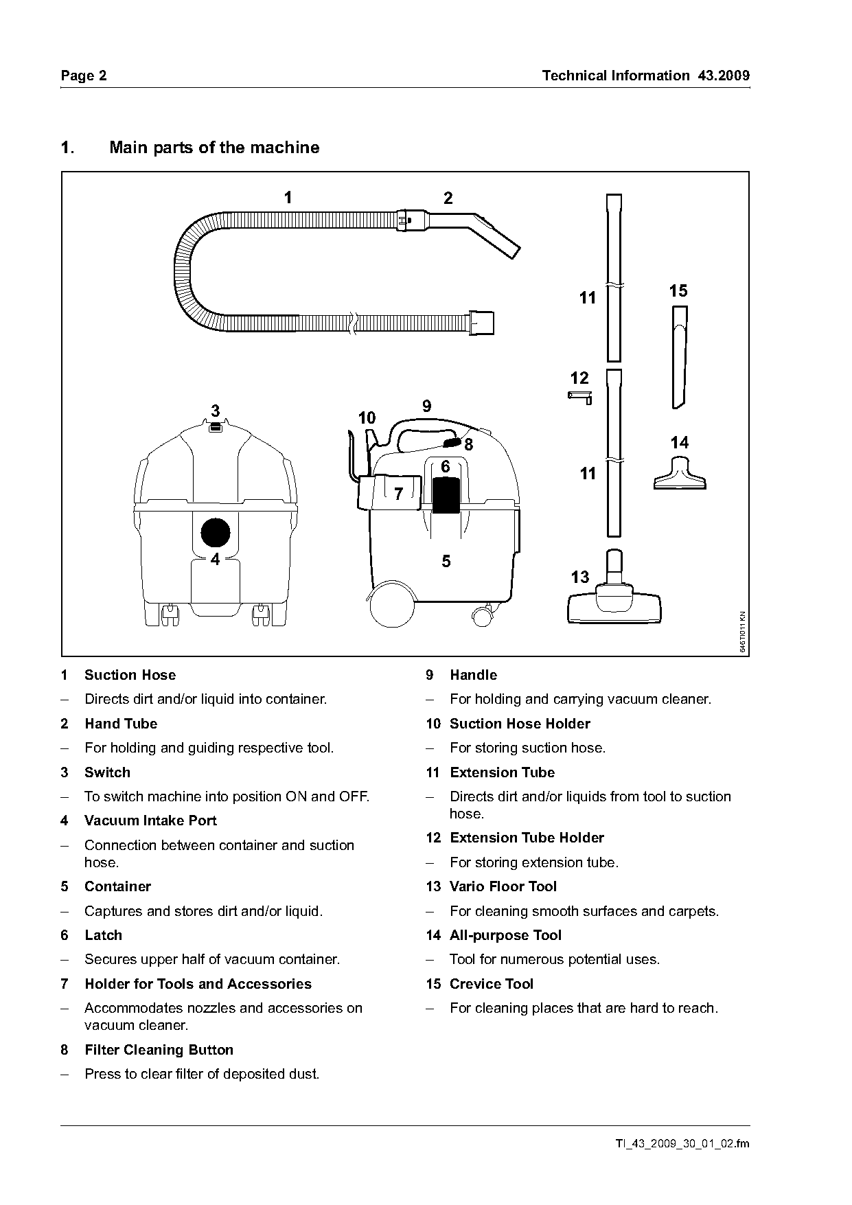
1.       Main parts of the machine

                                       1                       2

                                                                                     11             15

                                                                                   12
                          3                                9
                                                  10
                                                                   8                                14
                                                               6                     11
                                                       7

                          4                                    5
                                                                                   13

                                                                                                                  646TI011 KN
1    Suction Hose                                          9   Handle
–    Directs dirt and/or liquid into container.            –   For holding and carrying vacuum cleaner.
2    Hand Tube                                             10 Suction Hose Holder
–    For holding and guiding respective tool.              –   For storing suction hose.
3    Switch                                                11 Extension Tube
–    To switch machine into position ON and OFF.           –   Directs dirt and/or liquids from tool to suction
                                                               hose.
4    Vacuum Intake Port
                                                           12 Extension Tube Holder
–    Connection between container and suction
     hose.                                                 –   For storing extension tube.
5    Container                                             13 Vario Floor Tool
–    Captures and stores dirt and/or liquid.               –   For cleaning smooth surfaces and carpets.
6    Latch                                                 14 All-purpose Tool
–    Secures upper half of vacuum container.               –   Tool for numerous potential uses.
7    Holder for Tools and Accessories                      15 Crevice Tool
–    Accommodates nozzles and accessories on               –   For cleaning places that are hard to reach.
     vacuum cleaner.
8    Filter Cleaning Button
–    Press to clear filter of deposited dust.

                                                                                           TI_43_2009_30_01_02.fm
Page 3 of 6
Text of page 3 — search, copy, screen readers
Technical Information 43.2009                                                                         Page 3

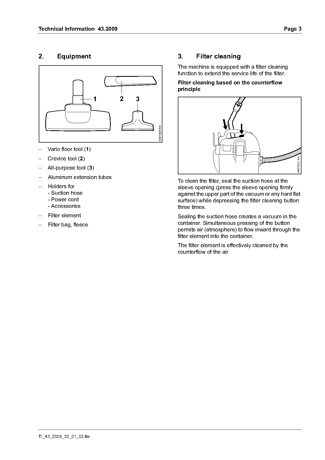
2.       Equipment                                    3.      Filter cleaning
                                                      The machine is equipped with a filter cleaning
                                                      function to extend the service life of the filter.
                                                      Filter cleaning based on the counterflow
                                                      principle
                            1   2   3

                                        646TI009 KN
–    Vario floor tool (1)
–    Crevice tool (2)

                                                                                                           646TI012 KN
–    All-purpose tool (3)
–    Aluminum extension tubes
                                                      To clean the filter, seal the suction hose at the
–    Holders for                                      sleeve opening (press the sleeve opening firmly
     - Suction hose                                   against the upper part of the vacuum or any hard flat
     - Power cord                                     surface) while depressing the filter cleaning button
     - Accessories                                    three times.
–    Filter element                                   Sealing the suction hose creates a vacuum in the
–    Filter bag, fleece                               container. Simultaneous pressing of the button
                                                      permits air (atmosphere) to flow inward through the
                                                      filter element into the container.
                                                      The filter element is effectively cleaned by the
                                                      counterflow of the air.

TI_43_2009_30_01_02.fm
Page 4 of 6
Text of page 4 — search, copy, screen readers
Page 4                                                                      Technical Information 43.2009

4.       Specifications                               5.          Service notes
Power supply                120 V, 60 Hz, 8.3 A       Repairs may only be performed by qualified
Power consumption           1000 W                    electricians with due regard for safety regulations
Mains fuse                  15 A                      and the Instruction Manual.
Protection class             II E                     Always disconnect the power plug from the power
Max. intake capacity, air   113 cf/min (3200 l/min)   source when performing all repairs.
Max. vacuum                 180 mbar / 71 in H20      After repairs have been made, the proper testing
                                                      procedures for electrical devices must be followed.
Length approx.              15 in (380 mm)
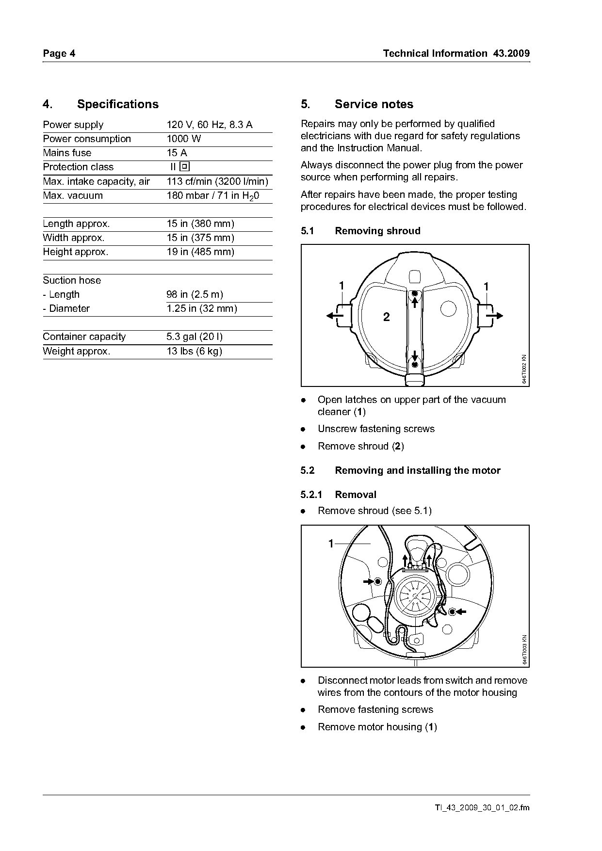
                                                      5.1         Removing shroud
Width approx.               15 in (375 mm)
Height approx.              19 in (485 mm)

Suction hose
                                                                  1                              1
- Length                    98 in (2.5 m)
- Diameter                  1.25 in (32 mm)
                                                                            2
Container capacity          5.3 gal (20 l)
Weight approx.              13 lbs (6 kg)

                                                                                                            646TI002 KN
                                                      .     Open latches on upper part of the vacuum
                                                            cleaner (1)
                                                      .     Unscrew fastening screws
                                                      .     Remove shroud (2)

                                                      5.2         Removing and installing the motor

                                                      5.2.1       Removal
                                                      .     Remove shroud (see 5.1)

                                                              1
                                                                                                            646TI003 KN

                                                      .     Disconnect motor leads from switch and remove
                                                            wires from the contours of the motor housing
                                                      .     Remove fastening screws
                                                      .     Remove motor housing (1)

                                                                                      TI_43_2009_30_01_02.fm
Page 5 of 6
Text of page 5 — search, copy, screen readers
Technical Information 43.2009                                                                       Page 5

                                                            3
                                    2

                                                                                                     2
                                                            4

                                                                                                             646TI006 KN
                                        646TI004 KN
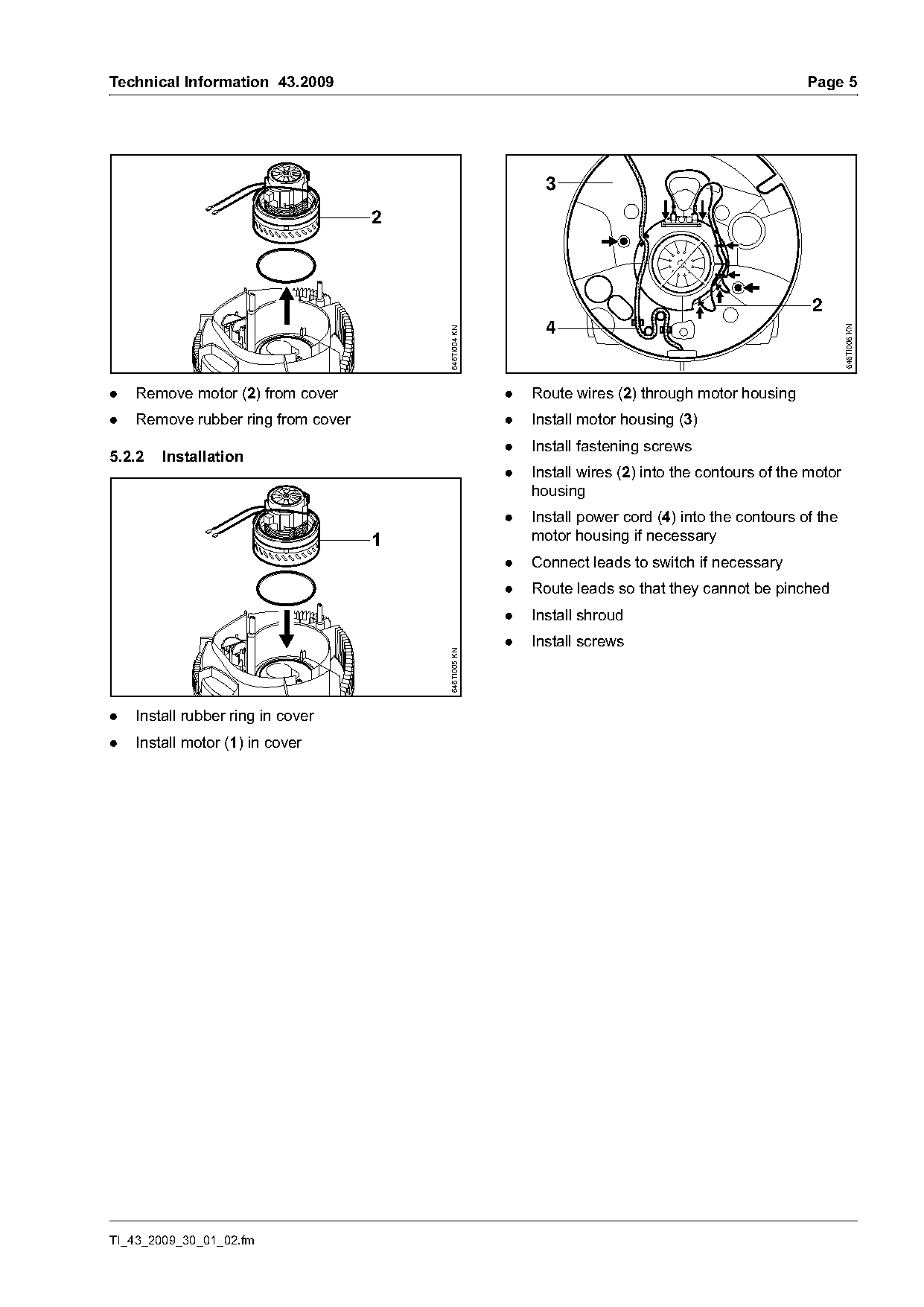
.   Remove motor (2) from cover                       .   Route wires (2) through motor housing
.   Remove rubber ring from cover                     .   Install motor housing (3)
                                                      .   Install fastening screws
5.2.2   Installation
                                                      .   Install wires (2) into the contours of the motor
                                                          housing
                                                      .   Install power cord (4) into the contours of the
                                    1                     motor housing if necessary
                                                      .   Connect leads to switch if necessary
                                                      .   Route leads so that they cannot be pinched
                                                      .   Install shroud
                                                      .   Install screws
                                        646TI005 KN

.   Install rubber ring in cover
.   Install motor (1) in cover

TI_43_2009_30_01_02.fm
Page 6 of 6
Text of page 6 — search, copy, screen readers
Page 6                                                                                    Technical Information 43.2009

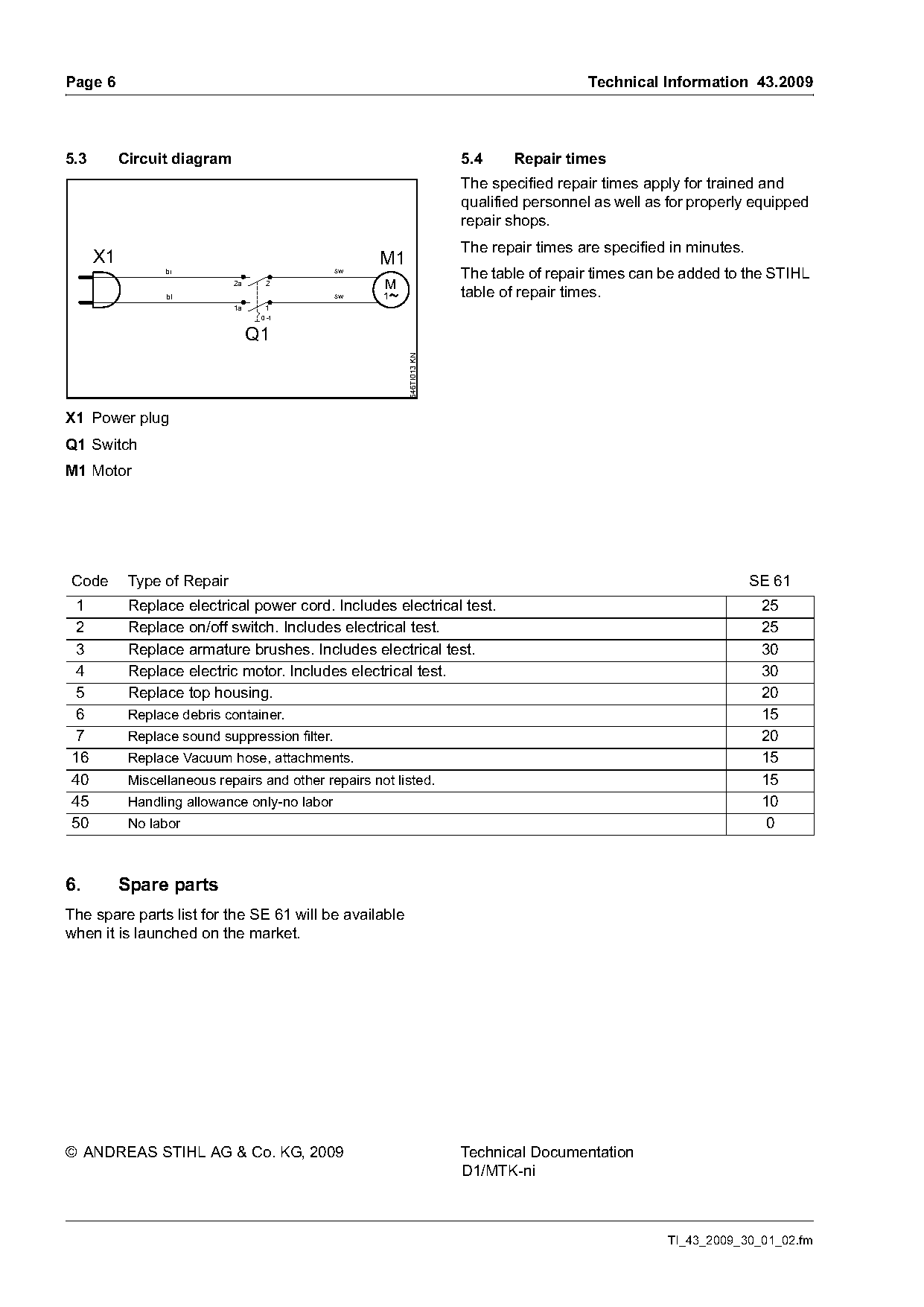
5.3        Circuit diagram                                              5.4    Repair times
                                                                        The specified repair times apply for trained and
                                                                        qualified personnel as well as for properly equipped
                                                                        repair shops.
                                                                        The repair times are specified in minutes.
      X1                                             M1
                  br                            sw
                                                                        The table of repair times can be added to the STIHL
                             2a     2                 M
                  bl                            sw    1                 table of repair times.
                             1a     1
                                   0 -1


                                                          646TI013 KN
X1 Power plug
Q1 Switch
M1 Motor

Code        Type of Repair                                                                                           SE 61
 1          Replace electrical power cord. Includes electrical test.                                                  25
 2          Replace on/off switch. Includes electrical test.                                                          25
 3          Replace armature brushes. Includes electrical test.                                                       30
 4          Replace electric motor. Includes electrical test.                                                         30
 5          Replace top housing.                                                                                      20
 6          Replace debris container.                                                                                 15
 7          Replace sound suppression filter.                                                                         20
16          Replace Vacuum hose, attachments.                                                                         15
40          Miscellaneous repairs and other repairs not listed.                                                       15
45          Handling allowance only-no labor                                                                          10
50          No labor                                                                                                   0

6.         Spare parts
The spare parts list for the SE 61 will be available
when it is launched on the market.

© ANDREAS STIHL AG & Co. KG, 2009                                       Technical Documentation
                                                                        D1/MTK-ni

                                                                                                      TI_43_2009_30_01_02.fm
Most of these PDFs embed fonts with a shifted character map, so the text above was recovered rather than copied — read it as a faithful but imperfect transcription, and treat the page image above each block as the authority where the two disagree — the figures exist only there, because they are vector drawings that text extraction cannot keep.