Technical Information · issue 3 of 2010
New STIHL HT 56 C-E Pole Pruner
IssueTI 3/2010
Full text
Page 1 of 14
Text of page 1 — search, copy, screen readers
STIH)

Technical Information                             03.2010

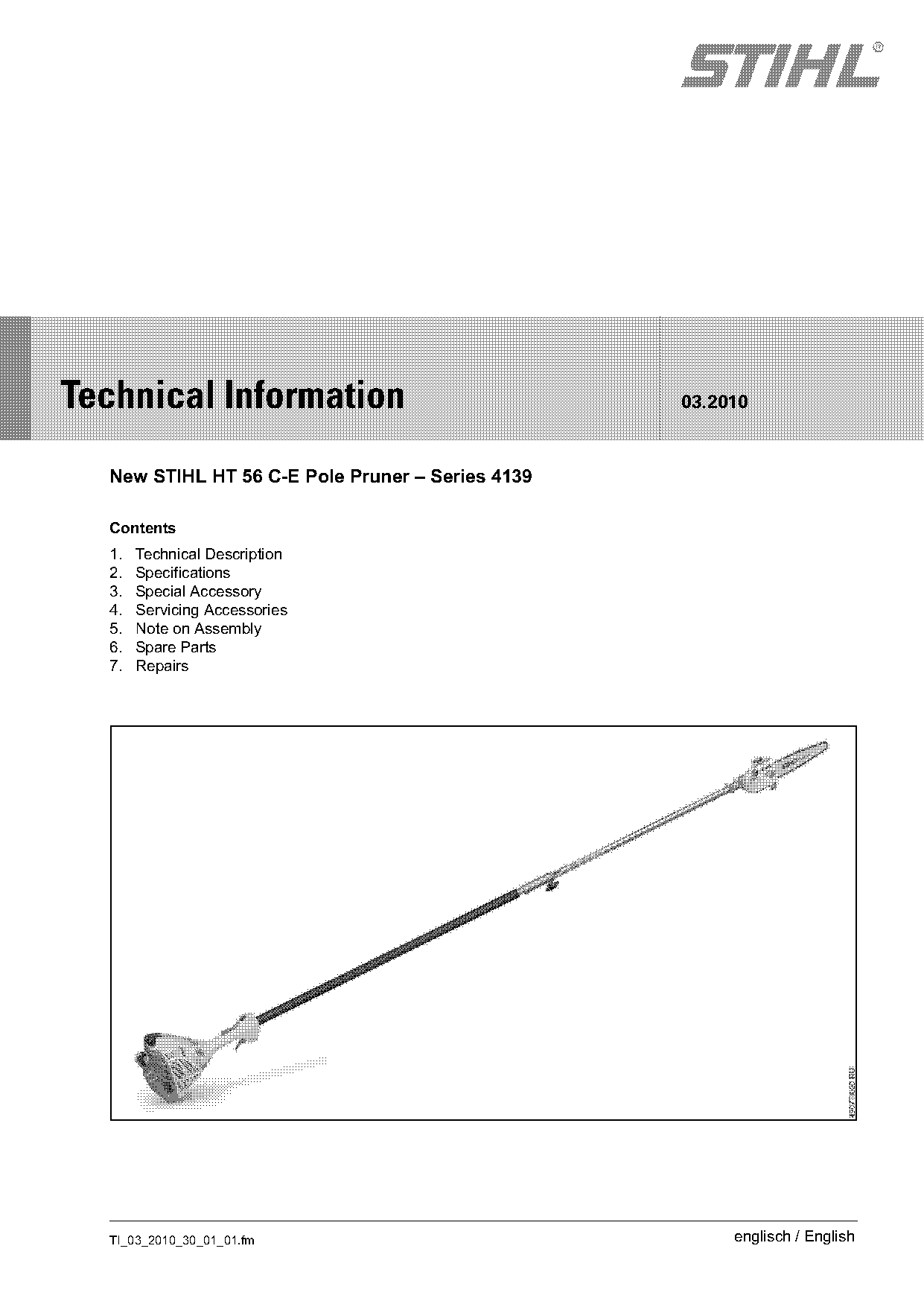
  New STIHL HT 56 C-E Pole Pruner – Series 4139

  Contents
  1.   Technical Description
  2.   Specifications
  3.   Special Accessory
  4.   Servicing Accessories
  5.   Note on Assembly
  6.   Spare Parts
  7.   Repairs

  TI_03_2010_30_01_01.fm                               englisch / English
Page 2 of 14
Text of page 2 — search, copy, screen readers
Page 2                                                                               Technical Information 03.2010

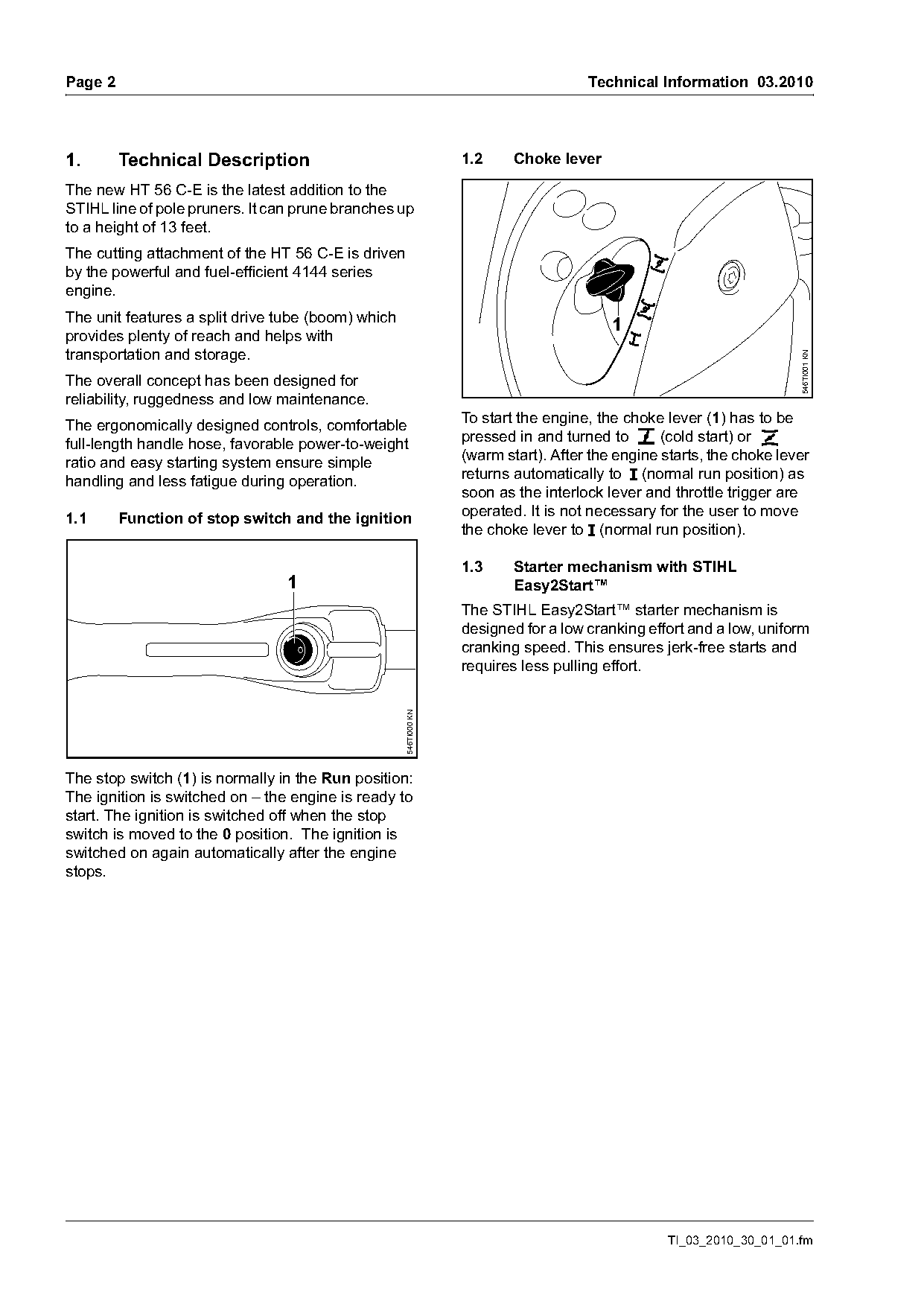
1.       Technical Description                                    1.2     Choke lever

The new HT 56 C-E is the latest addition to the
STIHL line of pole pruners. It can prune branches up
to a height of 13 feet.
The cutting attachment of the HT 56 C-E is driven
by the powerful and fuel-efficient 4144 series
engine.
The unit features a split drive tube (boom) which
                                                                                         1
provides plenty of reach and helps with
transportation and storage.

                                                                                                                      546TI001 KN
The overall concept has been designed for
reliability, ruggedness and low maintenance.
The ergonomically designed controls, comfortable                  To start the engine, the choke lever (1) has to be
full-length handle hose, favorable power-to-weight                pressed in and turned to g (cold start) or <
ratio and easy starting system ensure simple                      (warm start). After the engine starts, the choke lever
handling and less fatigue during operation.                       returns automatically to F (normal run position) as
                                                                  soon as the interlock lever and throttle trigger are
1.1      Function of stop switch and the ignition                 operated. It is not necessary for the user to move
                                                                  the choke lever to F (normal run position).

                                                                  1.3     Starter mechanism with STIHL
                                 1                                        Easy2Start™
                                                                  The STIHL Easy2Start™ starter mechanism is
                                                                  designed for a low cranking effort and a low, uniform
                                                                  cranking speed. This ensures jerk-free starts and
                                                                  requires less pulling effort.
                                                    546TI000 KN

The stop switch (1) is normally in the Run position:
The ignition is switched on – the engine is ready to
start. The ignition is switched off when the stop
switch is moved to the 0 position. The ignition is
switched on again automatically after the engine
stops.

                                                                                                 TI_03_2010_30_01_01.fm
Page 3 of 14
Text of page 3 — search, copy, screen readers
Technical Information 03.2010                                                                                         Page 3

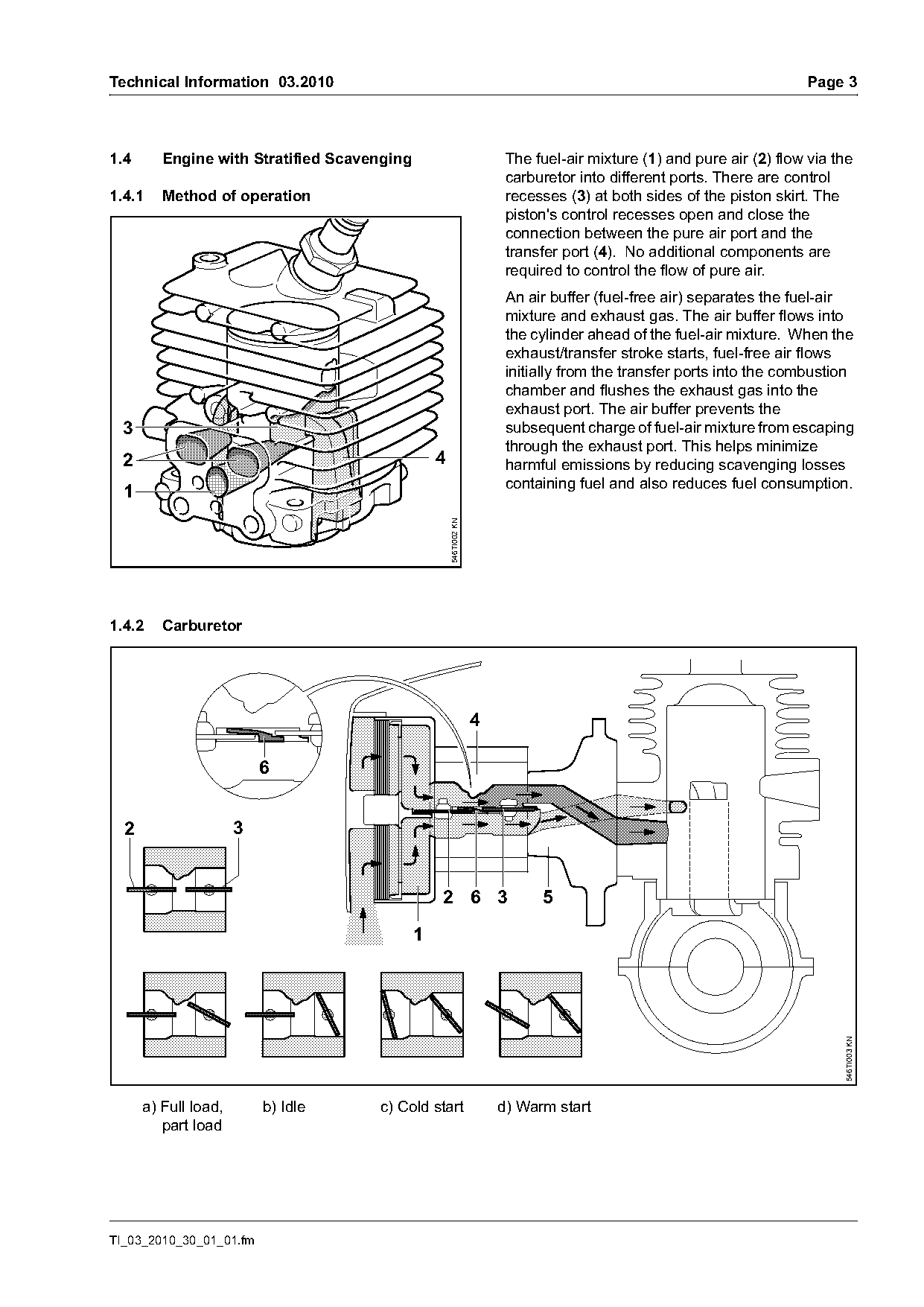
1.4      Engine with Stratified Scavenging                              The fuel-air mixture (1) and pure air (2) flow via the
                                                                        carburetor into different ports. There are control
1.4.1    Method of operation                                            recesses (3) at both sides of the piston skirt. The
                                                                        piston's control recesses open and close the
                                                                        connection between the pure air port and the
                                                                        transfer port (4). No additional components are
                                                                        required to control the flow of pure air.
                                                                        An air buffer (fuel-free air) separates the fuel-air
                                                                        mixture and exhaust gas. The air buffer flows into
                                                                        the cylinder ahead of the fuel-air mixture. When the
                                                                        exhaust/transfer stroke starts, fuel-free air flows
                                                                        initially from the transfer ports into the combustion
                                                                        chamber and flushes the exhaust gas into the
                                                                        exhaust port. The air buffer prevents the
  3                                                                     subsequent charge of fuel-air mixture from escaping
                                                                        through the exhaust port. This helps minimize
  2                                              4                      harmful emissions by reducing scavenging losses
                                                                        containing fuel and also reduces fuel consumption.
  1
                                                     546TI002 KN

1.4.2    Carburetor


  2                   3

                                                 2 6 3                       5

                                             1
                                                                                                                            546TI003 KN

      a) Full load,       b) Idle    c) Cold start                     d) Warm start
         part load

TI_03_2010_30_01_01.fm
Page 4 of 14
Text of page 4 — search, copy, screen readers
Page 4                                                                             Technical Information 03.2010

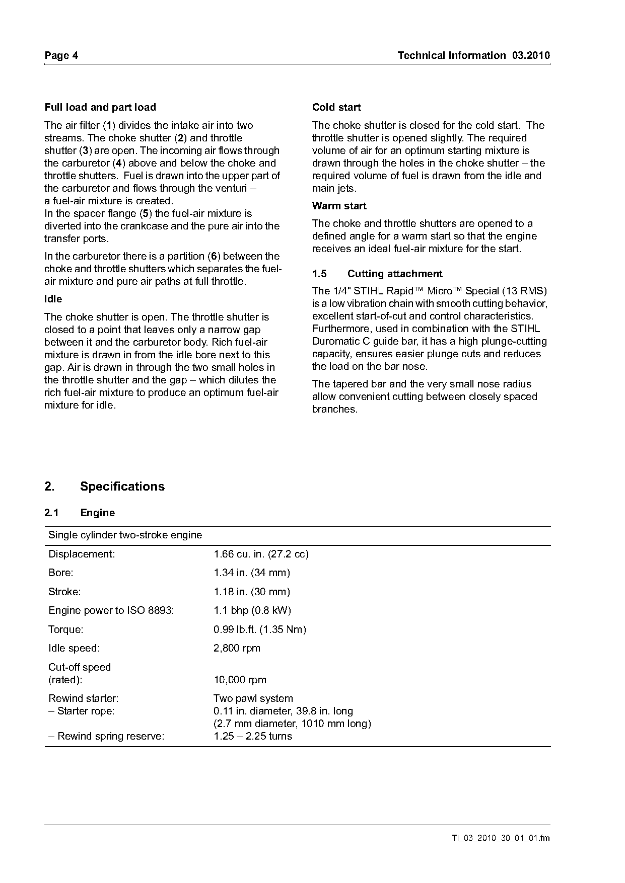
Full load and part load                                         Cold start
The air filter (1) divides the intake air into two              The choke shutter is closed for the cold start. The
streams. The choke shutter (2) and throttle                     throttle shutter is opened slightly. The required
shutter (3) are open. The incoming air flows through            volume of air for an optimum starting mixture is
the carburetor (4) above and below the choke and                drawn through the holes in the choke shutter – the
throttle shutters. Fuel is drawn into the upper part of         required volume of fuel is drawn from the idle and
the carburetor and flows through the venturi –                  main jets.
a fuel-air mixture is created.                                  Warm start
In the spacer flange (5) the fuel-air mixture is
diverted into the crankcase and the pure air into the           The choke and throttle shutters are opened to a
transfer ports.                                                 defined angle for a warm start so that the engine
                                                                receives an ideal fuel-air mixture for the start.
In the carburetor there is a partition (6) between the
choke and throttle shutters which separates the fuel-
                                                                1.5     Cutting attachment
air mixture and pure air paths at full throttle.
                                                                The 1/4" STIHL Rapid™ Micro™ Special (13 RMS)
Idle                                                            is a low vibration chain with smooth cutting behavior,
The choke shutter is open. The throttle shutter is              excellent start-of-cut and control characteristics.
closed to a point that leaves only a narrow gap                 Furthermore, used in combination with the STIHL
between it and the carburetor body. Rich fuel-air               Duromatic C guide bar, it has a high plunge-cutting
mixture is drawn in from the idle bore next to this             capacity, ensures easier plunge cuts and reduces
gap. Air is drawn in through the two small holes in             the load on the bar nose.
the throttle shutter and the gap – which dilutes the            The tapered bar and the very small nose radius
rich fuel-air mixture to produce an optimum fuel-air            allow convenient cutting between closely spaced
mixture for idle.                                               branches.

2.       Specifications

2.1      Engine

Single cylinder two-stroke engine
Displacement:                          1.66 cu. in. (27.2 cc)
Bore:                                  1.34 in. (34 mm)
Stroke:                                1.18 in. (30 mm)
Engine power to ISO 8893:              1.1 bhp (0.8 kW)
Torque:                                0.99 lb.ft. (1.35 Nm)
Idle speed:                            2,800 rpm
Cut-off speed
(rated):                               10,000 rpm
Rewind starter:                        Two pawl system
– Starter rope:                        0.11 in. diameter, 39.8 in. long
                                       (2.7 mm diameter, 1010 mm long)
– Rewind spring reserve:               1.25 – 2.25 turns

                                                                                               TI_03_2010_30_01_01.fm
Page 5 of 14
Text of page 5 — search, copy, screen readers
Technical Information 03.2010                                                               Page 5

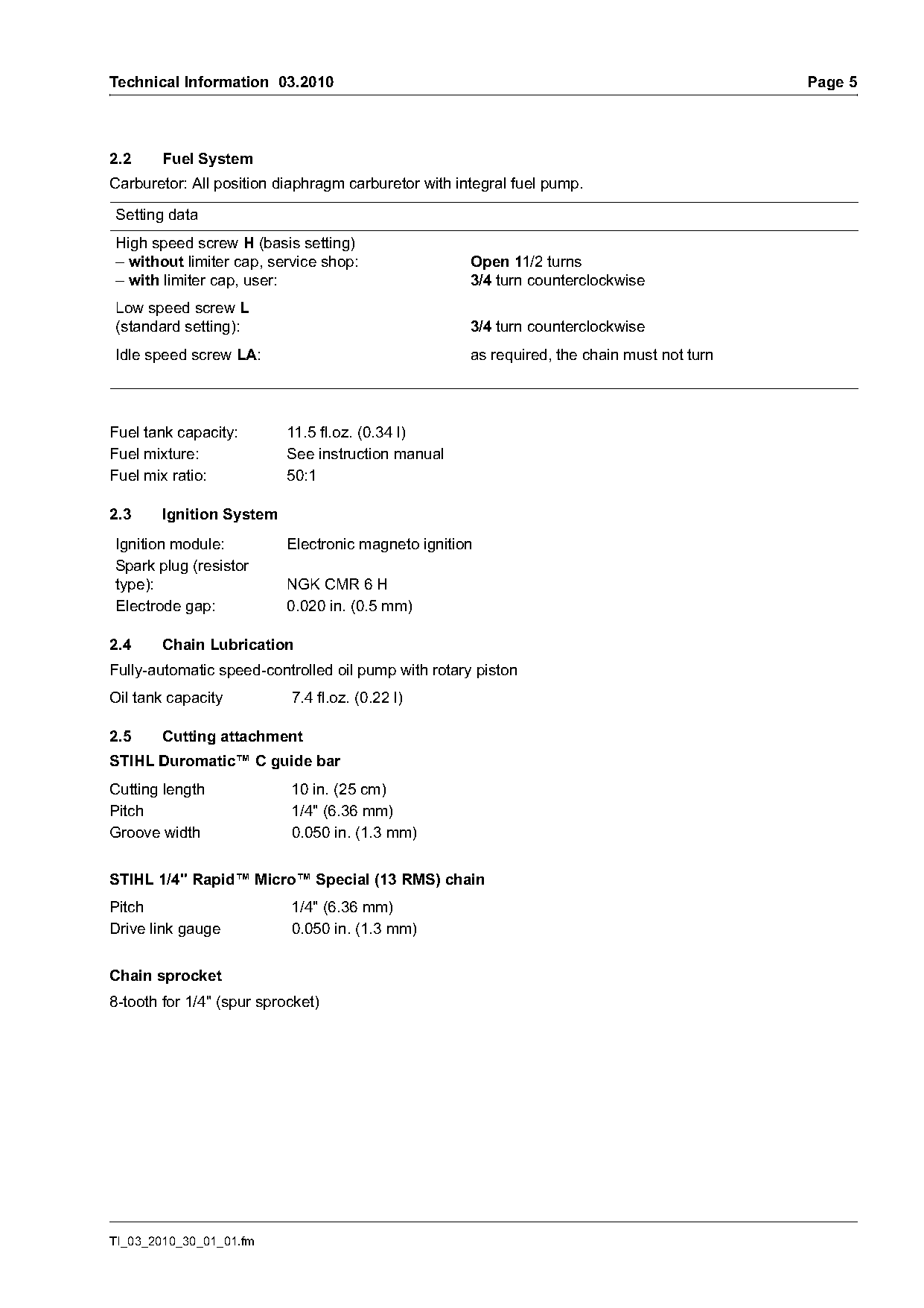
2.2     Fuel System
Carburetor: All position diaphragm carburetor with integral fuel pump.

Setting data
High speed screw H (basis setting)
– without limiter cap, service shop:                 Open 11/2 turns
– with limiter cap, user:                            3/4 turn counterclockwise
Low speed screw L
(standard setting):                                  3/4 turn counterclockwise
Idle speed screw LA:                                 as required, the chain must not turn

Fuel tank capacity:        11.5 fl.oz. (0.34 l)
Fuel mixture:              See instruction manual
Fuel mix ratio:            50:1

2.3     Ignition System
Ignition module:           Electronic magneto ignition
Spark plug (resistor
type):                     NGK CMR 6 H
Electrode gap:             0.020 in. (0.5 mm)

2.4     Chain Lubrication
Fully-automatic speed-controlled oil pump with rotary piston
Oil tank capacity          7.4 fl.oz. (0.22 l)

2.5     Cutting attachment
STIHL Duromatic™ C guide bar
Cutting length             10 in. (25 cm)
Pitch                      1/4" (6.36 mm)
Groove width               0.050 in. (1.3 mm)

STIHL 1/4" Rapid™ Micro™ Special (13 RMS) chain
Pitch                      1/4" (6.36 mm)
Drive link gauge           0.050 in. (1.3 mm)

Chain sprocket
8-tooth for 1/4" (spur sprocket)

TI_03_2010_30_01_01.fm
Page 6 of 14
Text of page 6 — search, copy, screen readers
Page 6                                                                       Technical Information 03.2010

2.6      Weight
Weight (dry, without bar and chain)
HT 56 C-E                   14.8 lbs. (6.7 kg)

2.7      Length
with cutting attachment
HT 56 C-E                   about 9.2 ft. (280 cm)

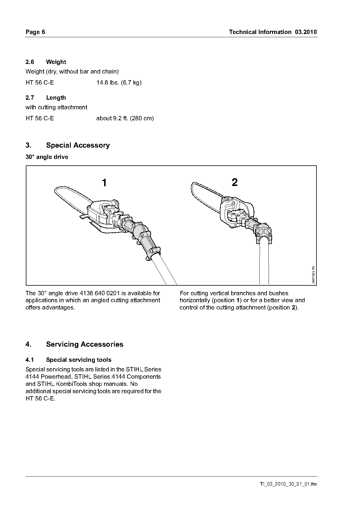
3.       Special Accessory
30° angle drive

                              1                                               2

                                                                                                               386TI003 KN
The 30° angle drive 4138 640 0201 is available for        For cutting vertical branches and bushes
applications in which an angled cutting attachment        horizontally (position 1) or for a better view and
offers advantages.                                        control of the cutting attachment (position 2).

4.       Servicing Accessories

4.1      Special servicing tools
Special servicing tools are listed in the STIHL Series
4144 Powerhead, STIHL Series 4144 Components
and STIHL KombiTools shop manuals. No
additional special servicing tools are required for the
HT 56 C-E.

                                                                                          TI_03_2010_30_01_01.fm
Page 7 of 14
Text of page 7 — search, copy, screen readers
Technical Information 03.2010                                                                       Page 7

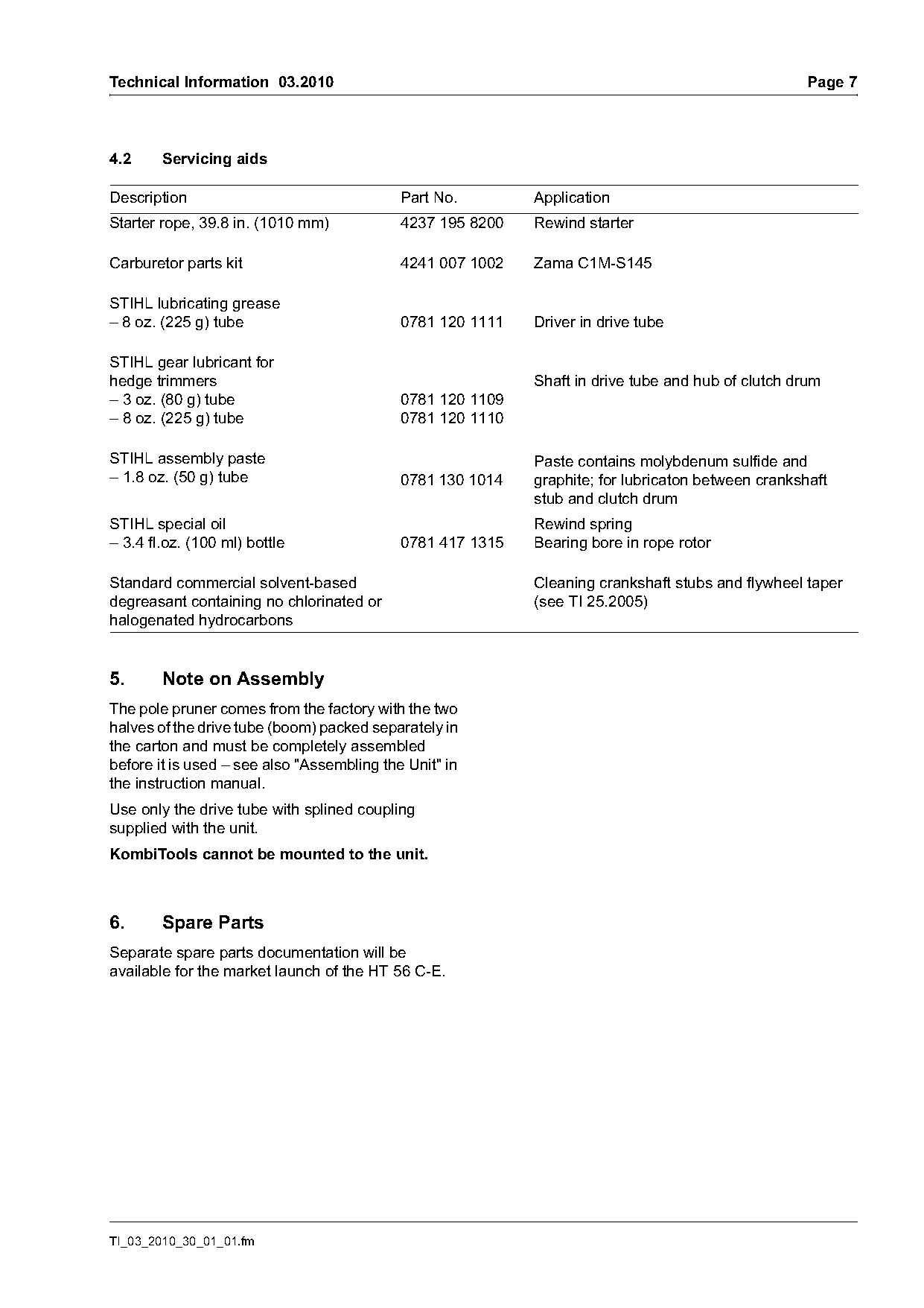
4.2     Servicing aids

Description                                 Part No.        Application
Starter rope, 39.8 in. (1010 mm)            4237 195 8200   Rewind starter

Carburetor parts kit                        4241 007 1002   Zama C1M-S145

STIHL lubricating grease
– 8 oz. (225 g) tube                        0781 120 1111   Driver in drive tube

STIHL gear lubricant for
hedge trimmers                                              Shaft in drive tube and hub of clutch drum
– 3 oz. (80 g) tube                         0781 120 1109
– 8 oz. (225 g) tube                        0781 120 1110

STIHL assembly paste                                        Paste contains molybdenum sulfide and
– 1.8 oz. (50 g) tube                       0781 130 1014   graphite; for lubricaton between crankshaft
                                                            stub and clutch drum
STIHL special oil                                           Rewind spring
– 3.4 fl.oz. (100 ml) bottle                0781 417 1315   Bearing bore in rope rotor

Standard commercial solvent-based                           Cleaning crankshaft stubs and flywheel taper
degreasant containing no chlorinated or                     (see TI 25.2005)
halogenated hydrocarbons

5.      Note on Assembly
The pole pruner comes from the factory with the two
halves of the drive tube (boom) packed separately in
the carton and must be completely assembled
before it is used – see also "Assembling the Unit" in
the instruction manual.
Use only the drive tube with splined coupling
supplied with the unit.
KombiTools cannot be mounted to the unit.

6.      Spare Parts
Separate spare parts documentation will be
available for the market launch of the HT 56 C-E.

TI_03_2010_30_01_01.fm
Page 8 of 14
Text of page 8 — search, copy, screen readers
Page 8                                                                       Technical Information 03.2010

7.       Repairs

7.1      Service manuals
The following service manuals can be used for
repairs to the HT 56 C-E pole pruner:

                 Engine (4144 Powerhead)                                                 Gearbox and
                     and rear drive tube                                               front drive tube
         Service manual                Service manual                                  Service manual
     Series 4144 Powerhead        Series 4144 Components                                 KombiTools
          0455 938 0123                0455 545 0123                                   0455 227 0123

Additional repair procedures are described in this
document.

7.2      Tightening torques                             7.4      Service Notes
The tightening torques are listed in the service
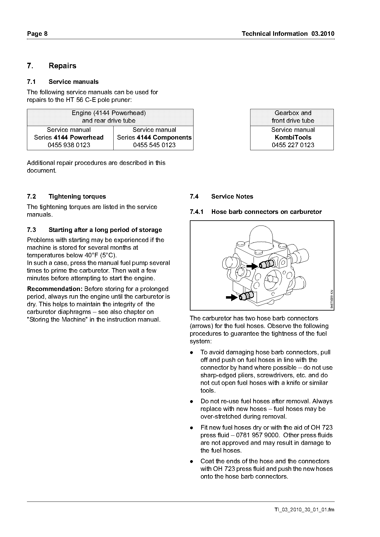
manuals.                                                7.4.1    Hose barb connectors on carburetor

7.3      Starting after a long period of storage
Problems with starting may be experienced if the
machine is stored for several months at
temperatures below 40°F (5°C).
In such a case, press the manual fuel pump several
times to prime the carburetor. Then wait a few
minutes before attempting to start the engine.
Recommendation: Before storing for a prolonged

                                                                                                             546TI009 KN
period, always run the engine until the carburetor is
dry. This helps to maintain the integrity of the
carburetor diaphragms – see also chapter on
"Storing the Machine" in the instruction manual.        The carburetor has two hose barb connectors
                                                        (arrows) for the fuel hoses. Observe the following
                                                        procedures to guarantee the tightness of the fuel
                                                        system:
                                                        .     To avoid damaging hose barb connectors, pull
                                                              off and push on fuel hoses in line with the
                                                              connector by hand where possible – do not use
                                                              sharp-edged pliers, screwdrivers, etc. and do
                                                              not cut open fuel hoses with a knife or similar
                                                              tools.
                                                        .     Do not re-use fuel hoses after removal. Always
                                                              replace with new hoses – fuel hoses may be
                                                              over-stretched during removal.
                                                        .     Fit new fuel hoses dry or with the aid of OH 723
                                                              press fluid – 0781 957 9000. Other press fluids
                                                              are not approved and may result in damage to
                                                              the fuel hoses.
                                                        .     Coat the ends of the hose and the connectors
                                                              with OH 723 press fluid and push the new hoses
                                                              onto the hose barb connectors.

                                                                                        TI_03_2010_30_01_01.fm
Page 9 of 14
Text of page 9 — search, copy, screen readers
Technical Information 03.2010                                                                                   Page 9

Note on OH 723 press fluid                                        7.4.3   Lubricating the clutch drum
OH 723 press fluid produces a lubricating film which              The hub of the clutch drum must be re-lubricated as
simplifies assembly. The lubricant evaporates after               necessary with gear lubricant for hedge trimmers
a short period – the hose is then tight.                          0781 120 1109 or 0781 120 1110 in order to avoid
                                                                  an increased rate of wear in the clutch drum.
Never use fuel, oil or grease as a lubricant for this
purpose. Fuel, oil and grease do not evaporate – the
hose may loosen or become detached.

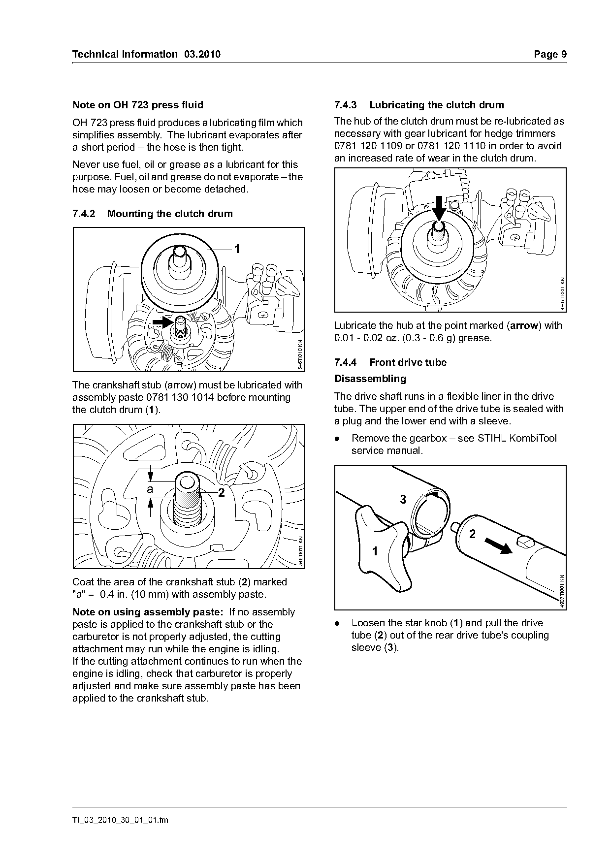
7.4.2   Mounting the clutch drum


                                                                                                                        4907TI007 KN
                                                                  Lubricate the hub at the point marked (arrow) with
                                                                  0.01 - 0.02 oz. (0.3 - 0.6 g) grease.
                                                   546TI010 KN

                                                                  7.4.4   Front drive tube
                                                                  Disassembling
The crankshaft stub (arrow) must be lubricated with
assembly paste 0781 130 1014 before mounting                      The drive shaft runs in a flexible liner in the drive
the clutch drum (1).                                              tube. The upper end of the drive tube is sealed with
                                                                  a plug and the lower end with a sleeve.
                                                                  .   Remove the gearbox – see STIHL KombiTool
                                                                      service manual.

                 a               2
                                                                                 3

                                                                                                 2
                                                    546TI011 KN

                                                                          1
                                                                                                                       4907TI001 KN

Coat the area of the crankshaft stub (2) marked
"a" = 0.4 in. (10 mm) with assembly paste.
Note on using assembly paste: If no assembly
paste is applied to the crankshaft stub or the                    .   Loosen the star knob (1) and pull the drive
carburetor is not properly adjusted, the cutting                      tube (2) out of the rear drive tube's coupling
attachment may run while the engine is idling.                        sleeve (3).
If the cutting attachment continues to run when the
engine is idling, check that carburetor is properly
adjusted and make sure assembly paste has been
applied to the crankshaft stub.

TI_03_2010_30_01_01.fm
Page 10 of 14
Text of page 10 — search, copy, screen readers
Page 10                                                                                     Technical Information 03.2010


                                                       4907TI002 KN

                                                                                                                                   4907TI004 KN
            6                                                                                        9

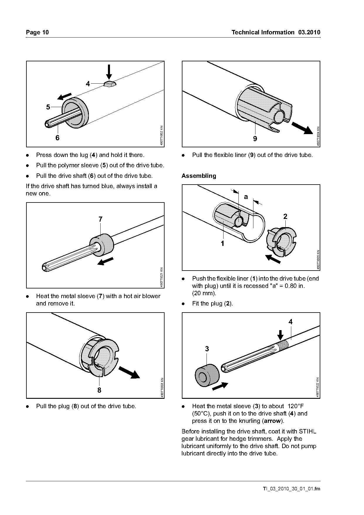
.   Press down the lug (4) and hold it there.                           .   Pull the flexible liner (9) out of the drive tube.
.   Pull the polymer sleeve (5) out of the drive tube.
.   Pull the drive shaft (6) out of the drive tube.                     Assembling
If the drive shaft has turned blue, always install a
new one.
                                                                                                 a

                             7                                                                                   2


                                                                                                                                   4907TI005 KN
                                                       4907TI021 KN

                                                                        .   Push the flexible liner (1) into the drive tube (end
                                                                            with plug) until it is recessed "a" = 0.80 in.
.   Heat the metal sleeve (7) with a hot air blower                         (20 mm).
    and remove it.                                                      .   Fit the plug (2).


                                                                                 3
                                                                                                                                 4907TI022 KN
                                                         4907TI003 KN


.   Pull the plug (8) out of the drive tube.                            .   Heat the metal sleeve (3) to about 120°F
                                                                            (50°C), push it on to the drive shaft (4) and
                                                                            press it on to the knurling (arrow).
                                                                        Before installing the drive shaft, coat it with STIHL
                                                                        gear lubricant for hedge trimmers. Apply the
                                                                        lubricant uniformly to the drive shaft. Do not pump
                                                                        lubricant directly into the drive tube.

                                                                                                         TI_03_2010_30_01_01.fm
Page 11 of 14
Text of page 11 — search, copy, screen readers
Technical Information 03.2010                                                                                   Page 11


                   4
                                                                       3


                                                                                                                          4907TI008 KN
                                                   4907TI018 KN
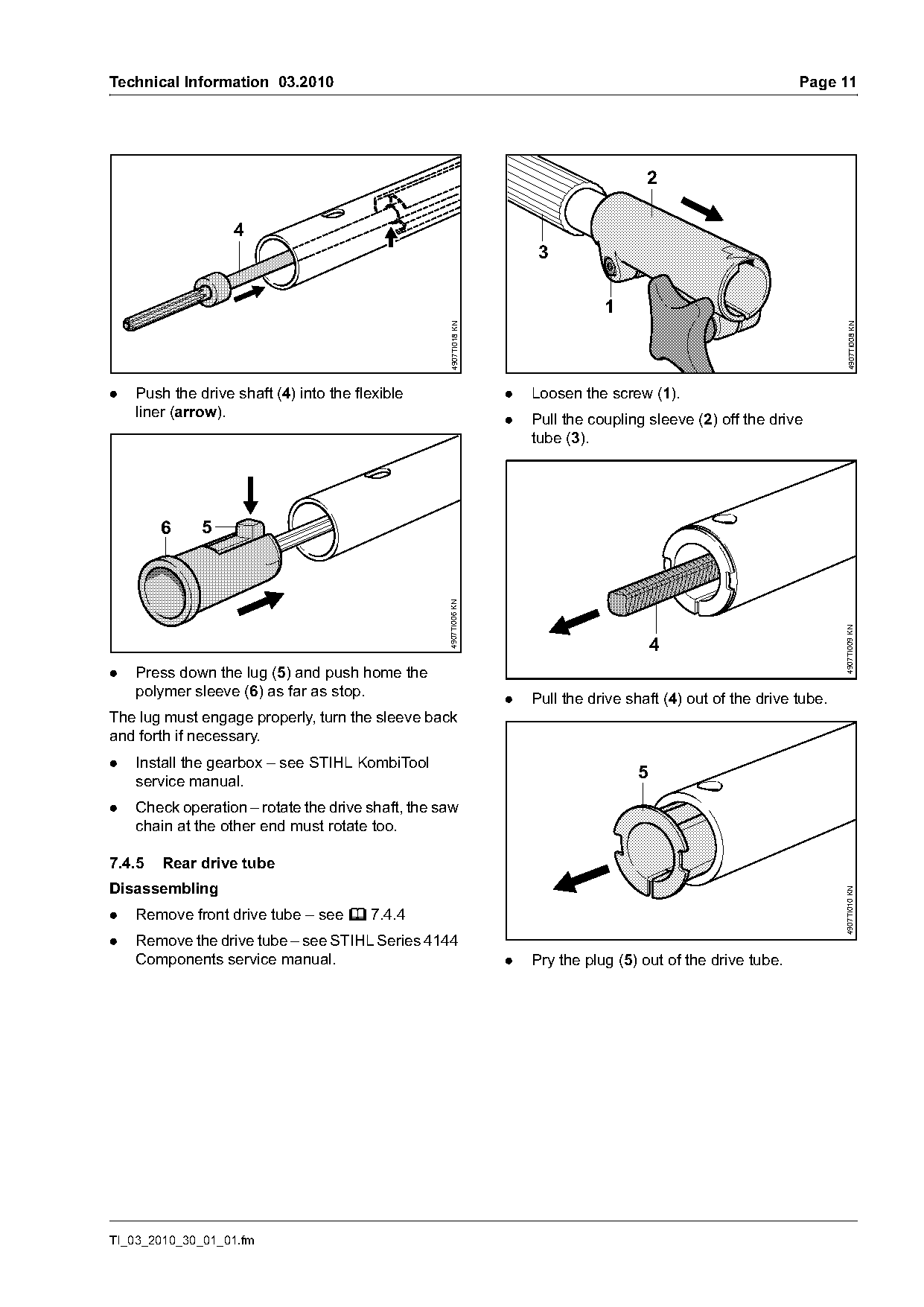
.   Push the drive shaft (4) into the flexible                    .   Loosen the screw (1).
    liner (arrow).                                                .   Pull the coupling sleeve (2) off the drive
                                                                      tube (3).

        6     5
                                                   4907TI006 KN

                                                                                                                        4907TI009 KN
                                                                                          4
.   Press down the lug (5) and push home the
    polymer sleeve (6) as far as stop.
                                                                  .   Pull the drive shaft (4) out of the drive tube.
The lug must engage properly, turn the sleeve back
and forth if necessary.
.   Install the gearbox – see STIHL KombiTool
    service manual.
                                                                                      5
.   Check operation – rotate the drive shaft, the saw
    chain at the other end must rotate too.

7.4.5   Rear drive tube
Disassembling
                                                                                                                        4907TI010 KN

.   Remove front drive tube – see b 7.4.4
.   Remove the drive tube – see STIHL Series 4144
    Components service manual.                                    .   Pry the plug (5) out of the drive tube.

TI_03_2010_30_01_01.fm
Page 12 of 14
Text of page 12 — search, copy, screen readers
Page 12                                                                                       Technical Information 03.2010

                                                                                               2
                                                                                                              1

                                                         4907TI011 KN

                                                                                                                              4907TI014 KN
                        6

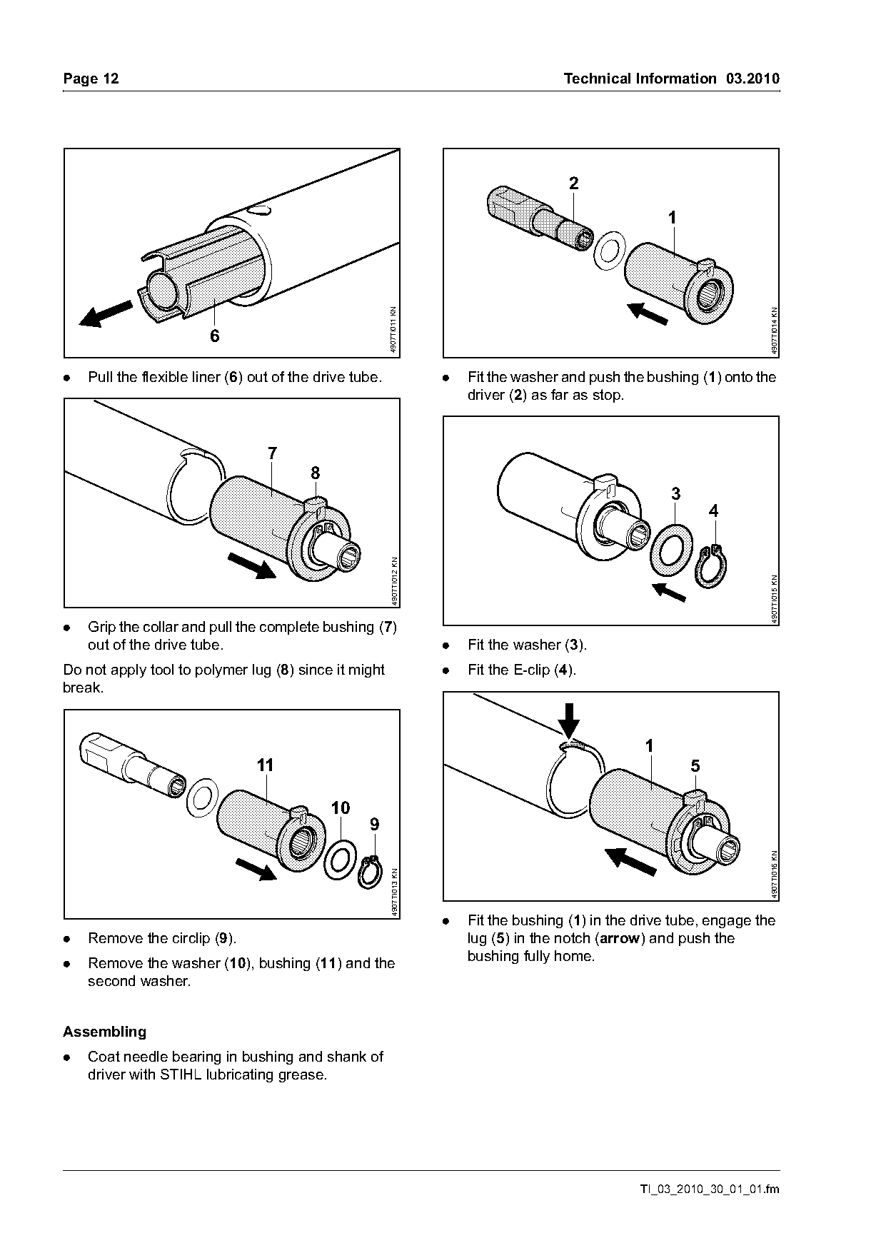
.   Pull the flexible liner (6) out of the drive tube.                    .   Fit the washer and push the bushing (1) onto the
                                                                              driver (2) as far as stop.

                                  7
                                         8
                                                                                                              3
                                                                                                                      4
                                                           4907TI012 KN

                                                                                                                              4907TI015 KN
.   Grip the collar and pull the complete bushing (7)
    out of the drive tube.                                                .   Fit the washer (3).
Do not apply tool to polymer lug (8) since it might                       .   Fit the E-clip (4).
break.

                                                                                                          1
                                11                                                                                5

                                             10
                                                   9
                                                                                                                              4907TI016 KN
                                                           4907TI013 KN

                                                                          .   Fit the bushing (1) in the drive tube, engage the
.   Remove the circlip (9).                                                   lug (5) in the notch (arrow) and push the
.   Remove the washer (10), bushing (11) and the                              bushing fully home.
    second washer.

Assembling
.   Coat needle bearing in bushing and shank of
    driver with STIHL lubricating grease.

                                                                                                         TI_03_2010_30_01_01.fm
Page 13 of 14
Text of page 13 — search, copy, screen readers
Technical Information 03.2010                                                                                      Page 13

                              b
                                                                                                 9


                                                                                   10
                                        6

                                                       4907TI017 KN

                                                                                                                            4907TI020 KN
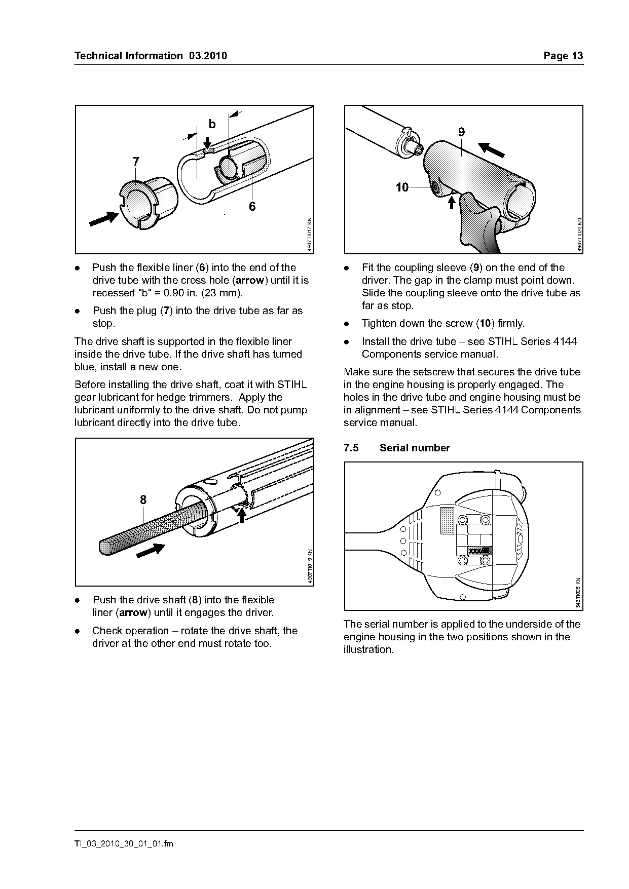
.   Push the flexible liner (6) into the end of the                   .     Fit the coupling sleeve (9) on the end of the
    drive tube with the cross hole (arrow) until it is                      driver. The gap in the clamp must point down.
    recessed "b" = 0.90 in. (23 mm).                                        Slide the coupling sleeve onto the drive tube as
.   Push the plug (7) into the drive tube as far as                         far as stop.
    stop.                                                             .     Tighten down the screw (10) firmly.
The drive shaft is supported in the flexible liner                    .     Install the drive tube – see STIHL Series 4144
inside the drive tube. If the drive shaft has turned                        Components service manual.
blue, install a new one.
                                                                      Make sure the setscrew that secures the drive tube
Before installing the drive shaft, coat it with STIHL                 in the engine housing is properly engaged. The
gear lubricant for hedge trimmers. Apply the                          holes in the drive tube and engine housing must be
lubricant uniformly to the drive shaft. Do not pump                   in alignment – see STIHL Series 4144 Components
lubricant directly into the drive tube.                               service manual.

                                                                      7.5      Serial number

              8
                                                       4907TI019 KN

                                                                                                                          546TI005 KN

.   Push the drive shaft (8) into the flexible
    liner (arrow) until it engages the driver.
                                                                      The serial number is applied to the underside of the
.   Check operation – rotate the drive shaft, the
                                                                      engine housing in the two positions shown in the
    driver at the other end must rotate too.
                                                                      illustration.

TI_03_2010_30_01_01.fm
Page 14 of 14
Text of page 14 — search, copy, screen readers
Page 14                                                               Technical Information 03.2010

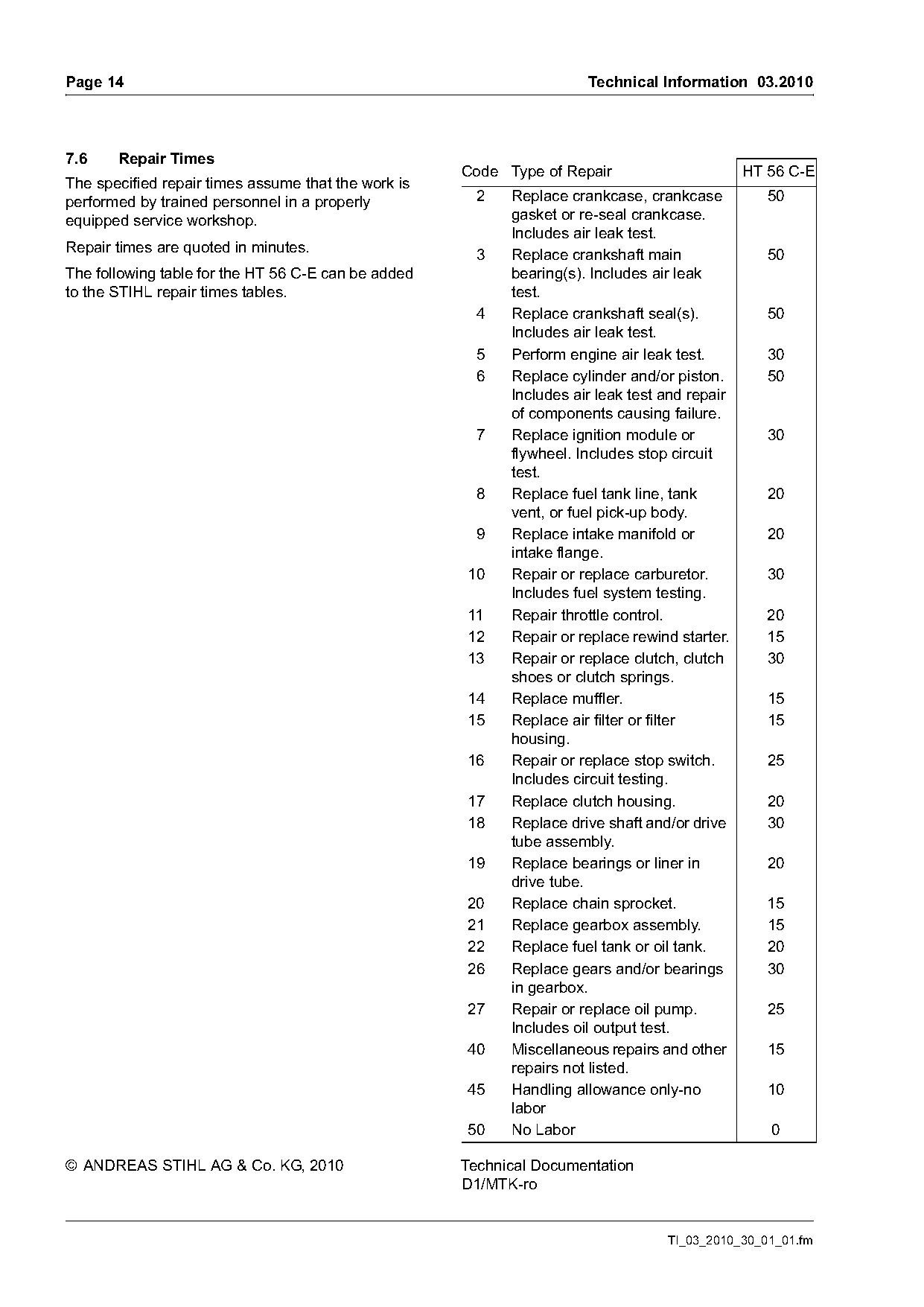
7.6    Repair Times
                                                     Code Type of Repair                       HT 56 C-E
The specified repair times assume that the work is
performed by trained personnel in a properly          2    Replace crankcase, crankcase           50
equipped service workshop.                                 gasket or re-seal crankcase.
                                                           Includes air leak test.
Repair times are quoted in minutes.
                                                      3    Replace crankshaft main                50
The following table for the HT 56 C-E can be added         bearing(s). Includes air leak
to the STIHL repair times tables.                          test.
                                                      4    Replace crankshaft seal(s).            50
                                                           Includes air leak test.
                                                      5    Perform engine air leak test.          30
                                                      6    Replace cylinder and/or piston.        50
                                                           Includes air leak test and repair
                                                           of components causing failure.
                                                      7    Replace ignition module or             30
                                                           flywheel. Includes stop circuit
                                                           test.
                                                      8    Replace fuel tank line, tank           20
                                                           vent, or fuel pick-up body.
                                                      9    Replace intake manifold or             20
                                                           intake flange.
                                                     10    Repair or replace carburetor.          30
                                                           Includes fuel system testing.
                                                     11    Repair throttle control.               20
                                                     12    Repair or replace rewind starter.      15
                                                     13    Repair or replace clutch, clutch       30
                                                           shoes or clutch springs.
                                                     14    Replace muffler.                       15
                                                     15    Replace air filter or filter           15
                                                           housing.
                                                     16    Repair or replace stop switch.         25
                                                           Includes circuit testing.
                                                     17    Replace clutch housing.                20
                                                     18    Replace drive shaft and/or drive       30
                                                           tube assembly.
                                                     19    Replace bearings or liner in           20
                                                           drive tube.
                                                     20    Replace chain sprocket.                15
                                                     21    Replace gearbox assembly.              15
                                                     22    Replace fuel tank or oil tank.         20
                                                     26    Replace gears and/or bearings          30
                                                           in gearbox.
                                                     27    Repair or replace oil pump.            25
                                                           Includes oil output test.
                                                     40    Miscellaneous repairs and other        15
                                                           repairs not listed.
                                                     45    Handling allowance only-no             10
                                                           labor
                                                     50    No Labor                               0

© ANDREAS STIHL AG & Co. KG, 2010                    Technical Documentation
                                                     D1/MTK-ro

                                                                                  TI_03_2010_30_01_01.fm
Most of these PDFs embed fonts with a shifted character map, so the text above was recovered rather than copied — read it as a faithful but imperfect transcription, and treat the page image above each block as the authority where the two disagree — the figures exist only there, because they are vector drawings that text extraction cannot keep.