Technical Information · issue 8 of 2010
New STIHL HSA 65 Cordless Hedge Trimmer
IssueTI 8/2010
Full text
Page 1 of 18
Text of page 1 — search, copy, screen readers
STIH)

Technical Information                                     08.2010

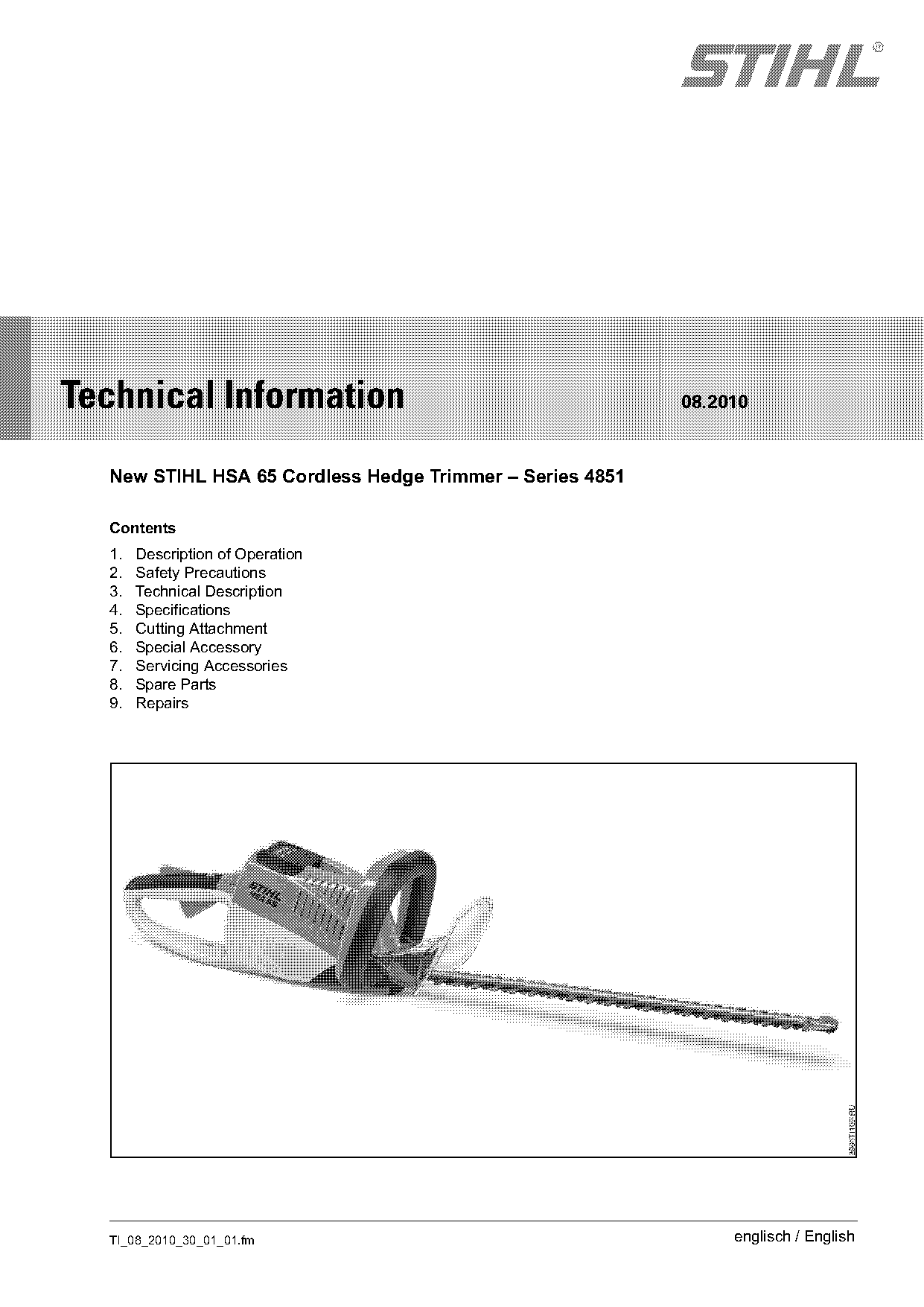
  New STIHL HSA 65 Cordless Hedge Trimmer – Series 4851

  Contents
  1.   Description of Operation
  2.   Safety Precautions
  3.   Technical Description
  4.   Specifications
  5.   Cutting Attachment
  6.   Special Accessory
  7.   Servicing Accessories
  8.   Spare Parts
  9.   Repairs

  TI_08_2010_30_01_01.fm                                       englisch / English
Page 2 of 18
Text of page 2 — search, copy, screen readers
Page 2                                                                  Technical Information 08.2010

This powerful STIHL cordless hedge trimmer marks      1.     Description of Operation
the advent of the new STIHL line of battery powered
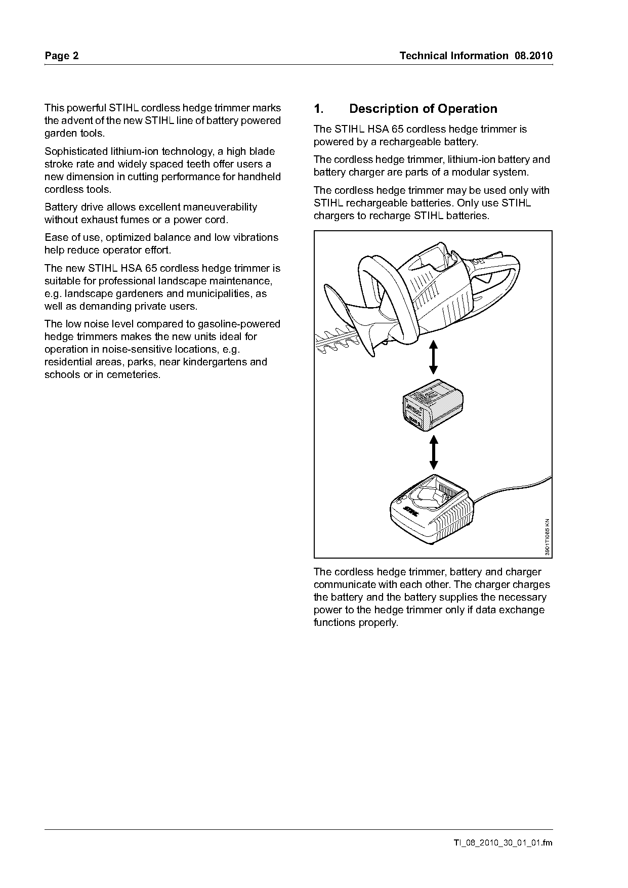
garden tools.                                         The STIHL HSA 65 cordless hedge trimmer is
                                                      powered by a rechargeable battery.
Sophisticated lithium-ion technology, a high blade
stroke rate and widely spaced teeth offer users a     The cordless hedge trimmer, lithium-ion battery and
new dimension in cutting performance for handheld     battery charger are parts of a modular system.
cordless tools.                                       The cordless hedge trimmer may be used only with
Battery drive allows excellent maneuverability        STIHL rechargeable batteries. Only use STIHL
without exhaust fumes or a power cord.                chargers to recharge STIHL batteries.

Ease of use, optimized balance and low vibrations
help reduce operator effort.
The new STIHL HSA 65 cordless hedge trimmer is
suitable for professional landscape maintenance,
e.g. landscape gardeners and municipalities, as
well as demanding private users.
The low noise level compared to gasoline-powered
hedge trimmers makes the new units ideal for
operation in noise-sensitive locations, e.g.
residential areas, parks, near kindergartens and
schools or in cemeteries.

                                                                                                        3901TI085 KN

                                                      The cordless hedge trimmer, battery and charger
                                                      communicate with each other. The charger charges
                                                      the battery and the battery supplies the necessary
                                                      power to the hedge trimmer only if data exchange
                                                      functions properly.

                                                                                    TI_08_2010_30_01_01.fm
Page 3 of 18
Text of page 3 — search, copy, screen readers
Technical Information 08.2010                                                                         Page 3

2.       Safety Precautions
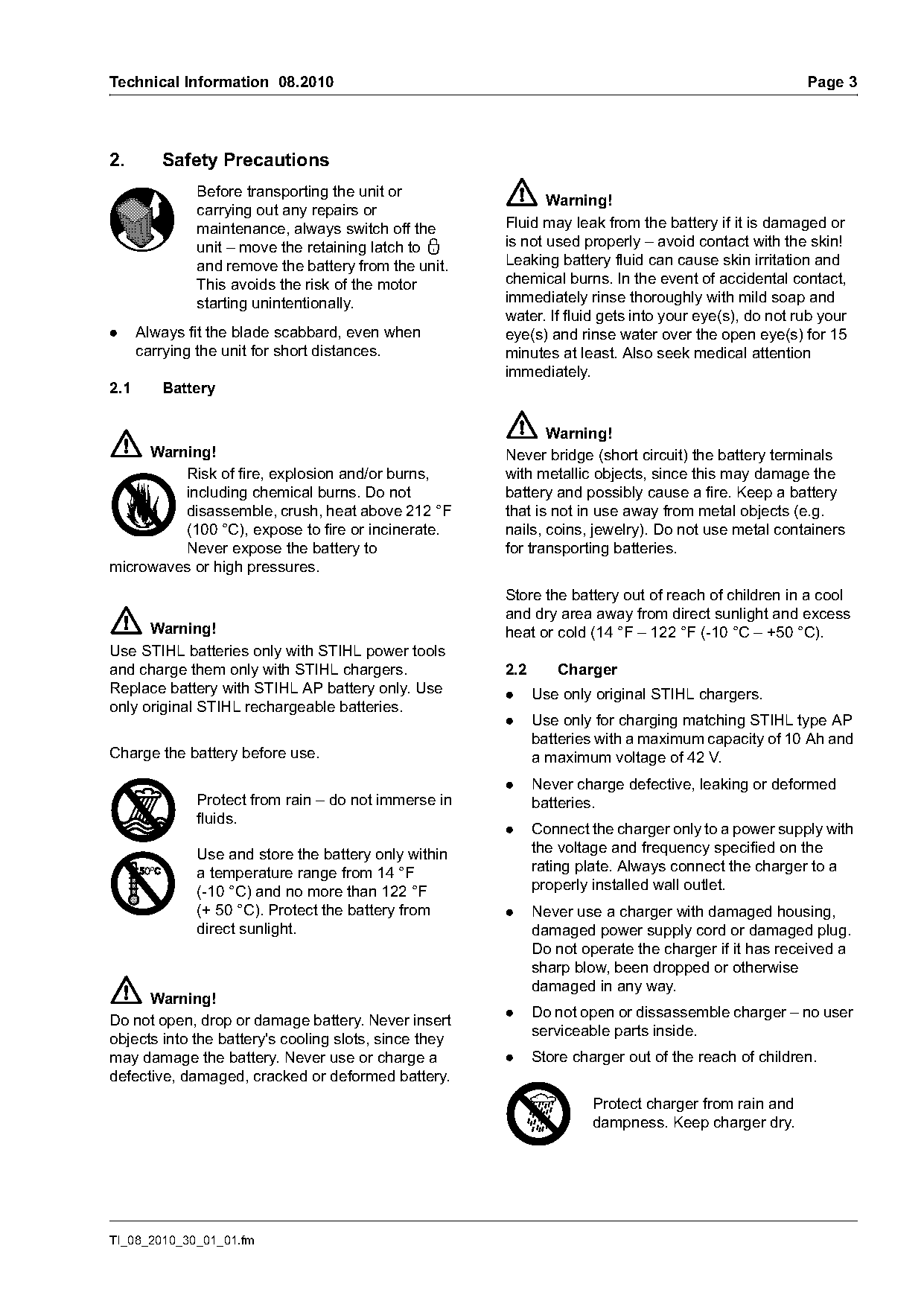
              Before transporting the unit or
                                                              Warning!
              carrying out any repairs or
              maintenance, always switch off the       Fluid may leak from the battery if it is damaged or
              unit – move the retaining latch to ƒ     is not used properly – avoid contact with the skin!
              and remove the battery from the unit.    Leaking battery fluid can cause skin irritation and
              This avoids the risk of the motor        chemical burns. In the event of accidental contact,
              starting unintentionally.                immediately rinse thoroughly with mild soap and
                                                       water. If fluid gets into your eye(s), do not rub your
.     Always fit the blade scabbard, even when         eye(s) and rinse water over the open eye(s) for 15
      carrying the unit for short distances.           minutes at least. Also seek medical attention
                                                       immediately.
2.1      Battery

                                                              Warning!
     Warning!                                          Never bridge (short circuit) the battery terminals
         Risk of fire, explosion and/or burns,         with metallic objects, since this may damage the
         including chemical burns. Do not              battery and possibly cause a fire. Keep a battery
         disassemble, crush, heat above 212 °F         that is not in use away from metal objects (e.g.
         (100 °C), expose to fire or incinerate.       nails, coins, jewelry). Do not use metal containers
         Never expose the battery to                   for transporting batteries.
microwaves or high pressures.
                                                       Store the battery out of reach of children in a cool
                                                       and dry area away from direct sunlight and excess
      Warning!                                         heat or cold (14 °F – 122 °F (-10 °C – +50 °C).
Use STIHL batteries only with STIHL power tools
and charge them only with STIHL chargers.              2.2      Charger
Replace battery with STIHL AP battery only. Use        .     Use only original STIHL chargers.
only original STIHL rechargeable batteries.
                                                       .     Use only for charging matching STIHL type AP
                                                             batteries with a maximum capacity of 10 Ah and
Charge the battery before use.                               a maximum voltage of 42 V.
                                                       .     Never charge defective, leaking or deformed
              Protect from rain – do not immerse in          batteries.
              fluids.
                                                       .     Connect the charger only to a power supply with
              Use and store the battery only within          the voltage and frequency specified on the
              a temperature range from 14 °F                 rating plate. Always connect the charger to a
              (-10 °C) and no more than 122 °F               properly installed wall outlet.
              (+ 50 °C). Protect the battery from      .     Never use a charger with damaged housing,
              direct sunlight.                               damaged power supply cord or damaged plug.
                                                             Do not operate the charger if it has received a
                                                             sharp blow, been dropped or otherwise
                                                             damaged in any way.
      Warning!
                                                       .     Do not open or dissassemble charger – no user
Do not open, drop or damage battery. Never insert
                                                             serviceable parts inside.
objects into the battery's cooling slots, since they
may damage the battery. Never use or charge a          .     Store charger out of the reach of children.
defective, damaged, cracked or deformed battery.
                                                                      Protect charger from rain and
                                                                      dampness. Keep charger dry.

TI_08_2010_30_01_01.fm
Page 4 of 18
Text of page 4 — search, copy, screen readers
Page 4                                                                       Technical Information 08.2010

                                                          .   Never use power supply cords that do not
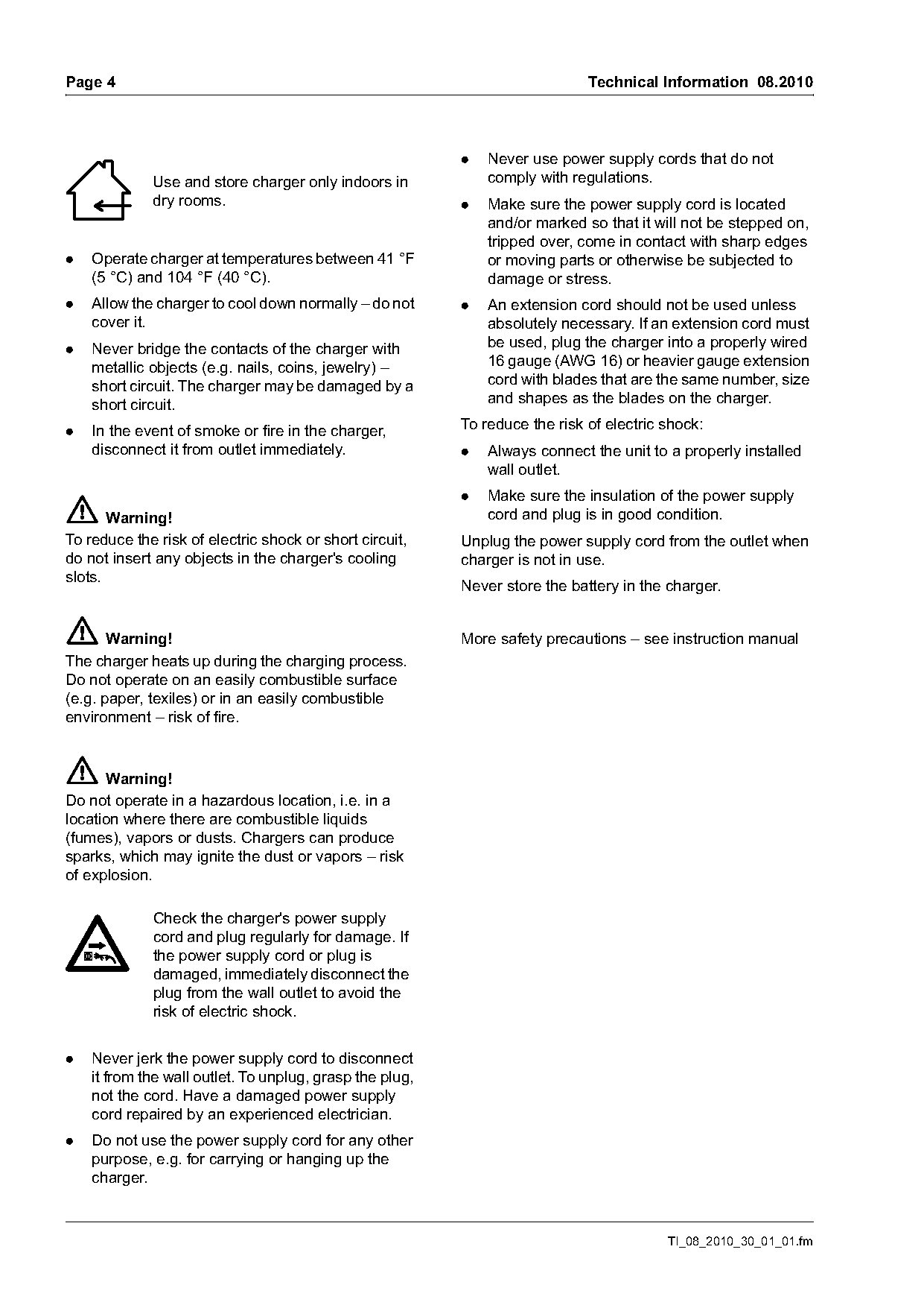
             Use and store charger only indoors in            comply with regulations.
             dry rooms.                                   .   Make sure the power supply cord is located
                                                              and/or marked so that it will not be stepped on,
                                                              tripped over, come in contact with sharp edges
.   Operate charger at temperatures between 41 °F             or moving parts or otherwise be subjected to
    (5 °C) and 104 °F (40 °C).                                damage or stress.
.   Allow the charger to cool down normally – do not      .   An extension cord should not be used unless
    cover it.                                                 absolutely necessary. If an extension cord must
.   Never bridge the contacts of the charger with             be used, plug the charger into a properly wired
    metallic objects (e.g. nails, coins, jewelry) –           16 gauge (AWG 16) or heavier gauge extension
    short circuit. The charger may be damaged by a            cord with blades that are the same number, size
    short circuit.                                            and shapes as the blades on the charger.

.   In the event of smoke or fire in the charger,         To reduce the risk of electric shock:
    disconnect it from outlet immediately.                .   Always connect the unit to a properly installed
                                                              wall outlet.
                                                          .   Make sure the insulation of the power supply
       Warning!                                               cord and plug is in good condition.
To reduce the risk of electric shock or short circuit,    Unplug the power supply cord from the outlet when
do not insert any objects in the charger's cooling        charger is not in use.
slots.
                                                          Never store the battery in the charger.

       Warning!                                           More safety precautions – see instruction manual
The charger heats up during the charging process.
Do not operate on an easily combustible surface
(e.g. paper, texiles) or in an easily combustible
environment – risk of fire.

       Warning!
Do not operate in a hazardous location, i.e. in a
location where there are combustible liquids
(fumes), vapors or dusts. Chargers can produce
sparks, which may ignite the dust or vapors – risk
of explosion.

             Check the charger's power supply
             cord and plug regularly for damage. If
             the power supply cord or plug is
             damaged, immediately disconnect the
             plug from the wall outlet to avoid the
             risk of electric shock.

.   Never jerk the power supply cord to disconnect
    it from the wall outlet. To unplug, grasp the plug,
    not the cord. Have a damaged power supply
    cord repaired by an experienced electrician.
.   Do not use the power supply cord for any other
    purpose, e.g. for carrying or hanging up the
    charger.

                                                                                         TI_08_2010_30_01_01.fm
Page 5 of 18
Text of page 5 — search, copy, screen readers
Technical Information 08.2010                                                                                       Page 5

3.      Technical Description                                        3.3       Operating instructions

3.1     Design, loop handle                                          3.3.1     Switching on


                                                                                                                             3901TI070 KN
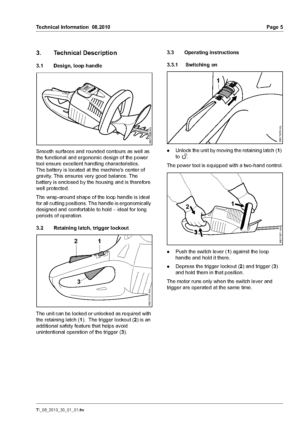
                                                      3901TI086 KN   .     Unlock the unit by moving the retaining latch (1)
Smooth surfaces and rounded contours as well as
the functional and ergonomic design of the power                           to ‚.
tool ensure excellent handling characteristics.                      The power tool is equipped with a two-hand control.
The battery is located at the machine's center of
gravity. This ensures very good balance. The
battery is enclosed by the housing and is therefore
well protected.
The wrap-around shape of the loop handle is ideal
for all cutting positions. The handle is ergonomically                                              1
designed and comfortable to hold – ideal for long                              2
periods of operation.

3.2     Retaining latch, trigger lockout

                                                                                                                             3901TI071 KN
                 2          1
                                                                     .     Push the switch lever (1) against the loop
                                                                           handle and hold it there.
                                                                     .     Depress the trigger lockout (2) and trigger (3)
                                                                           and hold them in that position.
                   3                                                 The motor runs only when the switch lever and
                                                                     trigger are operated at the same time.
                                                    3901TI101 KN

The unit can be locked or unlocked as required with
the retaining latch (1). The trigger lockout (2) is an
additional safety feature that helps avoid
unintentional operation of the trigger (3).

TI_08_2010_30_01_01.fm
Page 6 of 18
Text of page 6 — search, copy, screen readers
Page 6                                                                                   Technical Information 08.2010

3.3.2    Switching off                                                 3.5    Hang-up hole


                                                        3901TI103 KN

                                                                                                                        3901TI073 KN
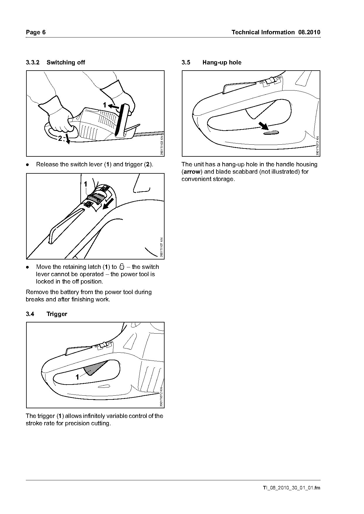
.     Release the switch lever (1) and trigger (2).                    The unit has a hang-up hole in the handle housing
                                                                       (arrow) and blade scabbard (not illustrated) for
                                                                       convenient storage.
                         1
                                                       3901TI107 KN

.     Move the retaining latch (1) to ƒ – the switch
      lever cannot be operated – the power tool is
      locked in the off position.
Remove the battery from the power tool during
breaks and after finishing work.

3.4      Trigger

                     1
                                                       3901TI072 KN

The trigger (1) allows infinitely variable control of the
stroke rate for precision cutting.

                                                                                                    TI_08_2010_30_01_01.fm
Page 7 of 18
Text of page 7 — search, copy, screen readers
Technical Information 08.2010                                                                    Page 7

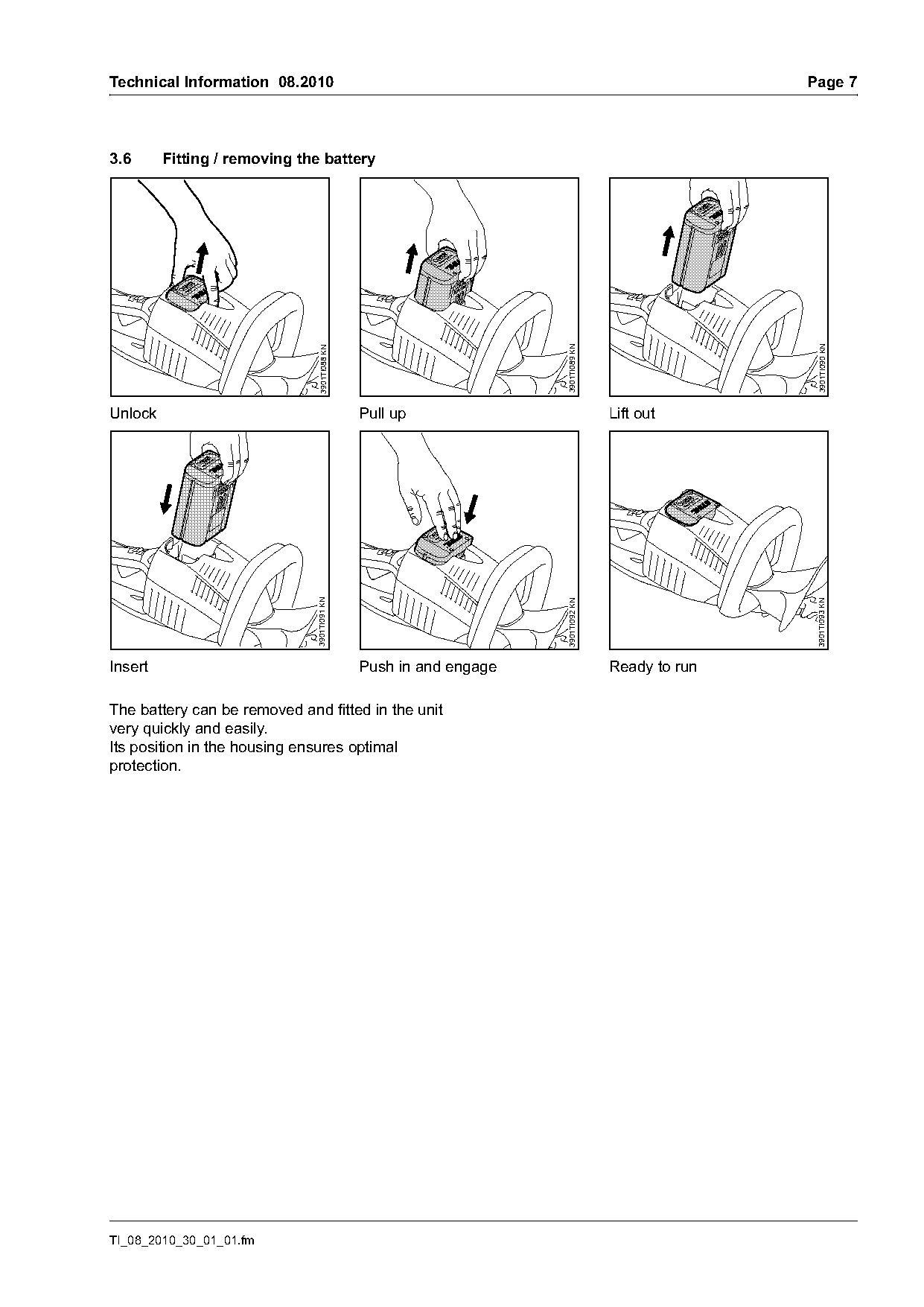
3.6      Fitting / removing the battery

                                                                                                  3901TI090 KN
                                                                   3901TI089 KN
                               3901TI088 KN

Unlock                                        Pull up                             Lift out
                              3901TI091 KN

                                                                                                  3901TI093 KN
                                                                   3901TI092 KN

Insert                                        Push in and engage                  Ready to run

The battery can be removed and fitted in the unit
very quickly and easily.
Its position in the housing ensures optimal
protection.

TI_08_2010_30_01_01.fm
Page 8 of 18
Text of page 8 — search, copy, screen readers
Page 8                                                                                  Technical Information 08.2010

3.7      Battery                                                     3.7.2   Construction and characteristics
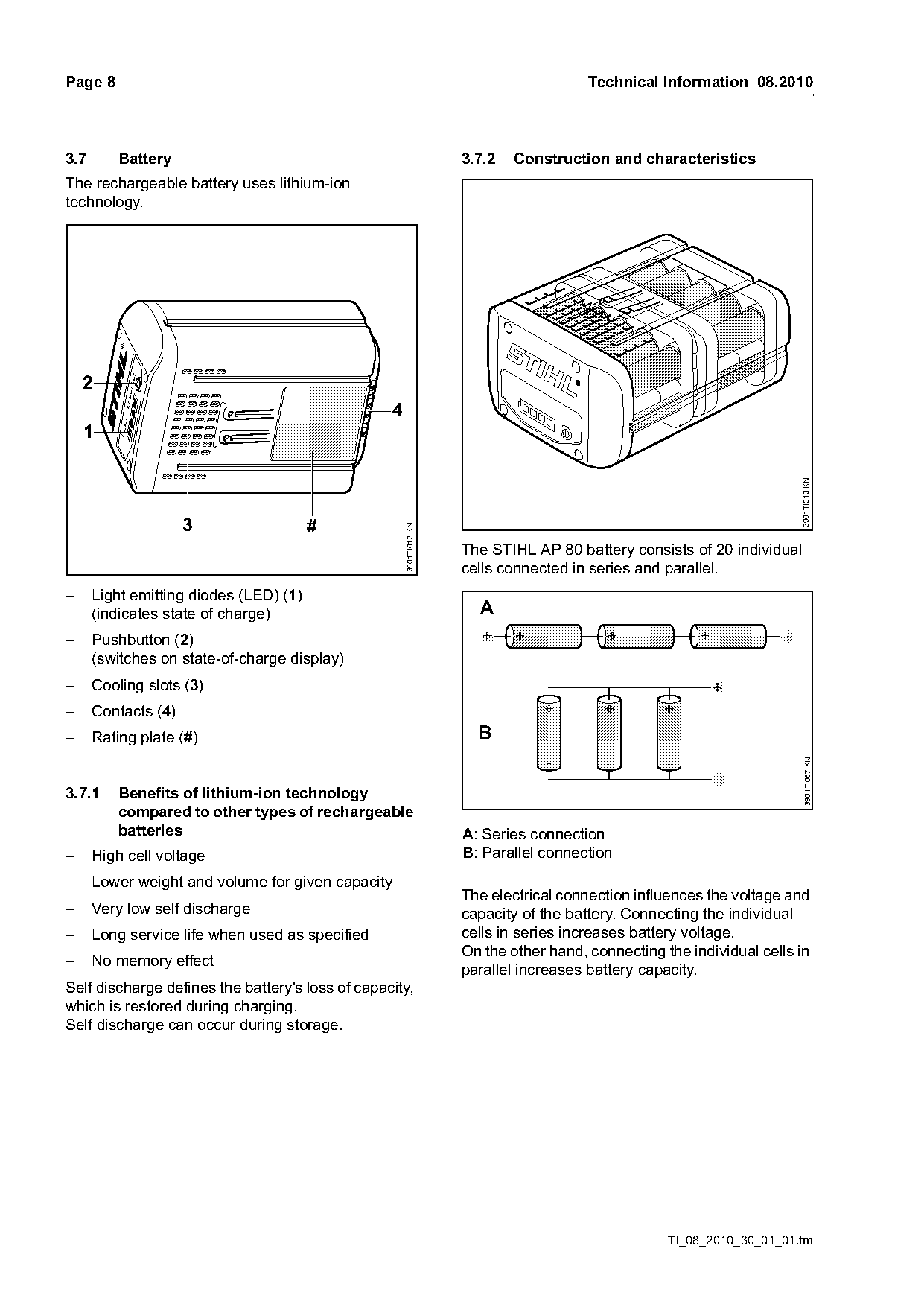
The rechargeable battery uses lithium-ion
technology.

    2
                                                  4
    1

                                                                                                                        3901TI013 KN
                     3                  #
                                                      3901TI012 KN

                                                                     The STIHL AP 80 battery consists of 20 individual
                                                                     cells connected in series and parallel.
–     Light emitting diodes (LED) (1)
      (indicates state of charge)                                      A
–     Pushbutton (2)
      (switches on state-of-charge display)
–     Cooling slots (3)
–     Contacts (4)
–     Rating plate (#)                                                 B

                                                                                                                          3901TI067 KN
3.7.1    Benefits of lithium-ion technology
         compared to other types of rechargeable
         batteries                                                   A: Series connection
–     High cell voltage                                              B: Parallel connection
–     Lower weight and volume for given capacity
                                                                     The electrical connection influences the voltage and
–     Very low self discharge                                        capacity of the battery. Connecting the individual
–     Long service life when used as specified                       cells in series increases battery voltage.
                                                                     On the other hand, connecting the individual cells in
–     No memory effect
                                                                     parallel increases battery capacity.
Self discharge defines the battery's loss of capacity,
which is restored during charging.
Self discharge can occur during storage.

                                                                                                    TI_08_2010_30_01_01.fm
Page 9 of 18
Text of page 9 — search, copy, screen readers
Technical Information 08.2010                                                                                    Page 9

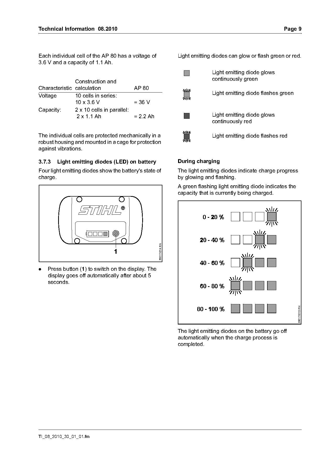
Each individual cell of the AP 80 has a voltage of                  Light emitting diodes can glow or flash green or red.
3.6 V and a capacity of 1.1 Ah.
                                                                                  Light emitting diode glows
                                                                                  continuously green
               Construction and
Characteristic calculation               AP 80
Voltage        10 cells in series:                                                Light emitting diode flashes green
               10 x 3.6 V                = 36 V
Capacity:      2 x 10 cells in parallel:
                2 x 1.1 Ah               = 2.2 Ah                                 Light emitting diode glows
                                                                                  continuously red

The individual cells are protected mechanically in a                              Light emitting diode flashes red
robust housing and mounted in a cage for protection
against vibrations.

3.7.3   Light emitting diodes (LED) on battery                      During charging
Four light emitting diodes show the battery's state of              The light emitting diodes indicate charge progress
charge.                                                             by glowing and flashing.
                                                                    A green flashing light emitting diode indicates the
                                                                    capacity that is currently being charged.
                                                     3901TI014 KN


.   Press button (1) to switch on the display. The
    display goes off automatically after about 5
    seconds.

                                                                                                                          3901TI015 KN

                                                                    The light emitting diodes on the battery go off
                                                                    automatically when the charge process is
                                                                    completed.

TI_08_2010_30_01_01.fm
Page 10 of 18
Text of page 10 — search, copy, screen readers
Page 10                                                                              Technical Information 08.2010

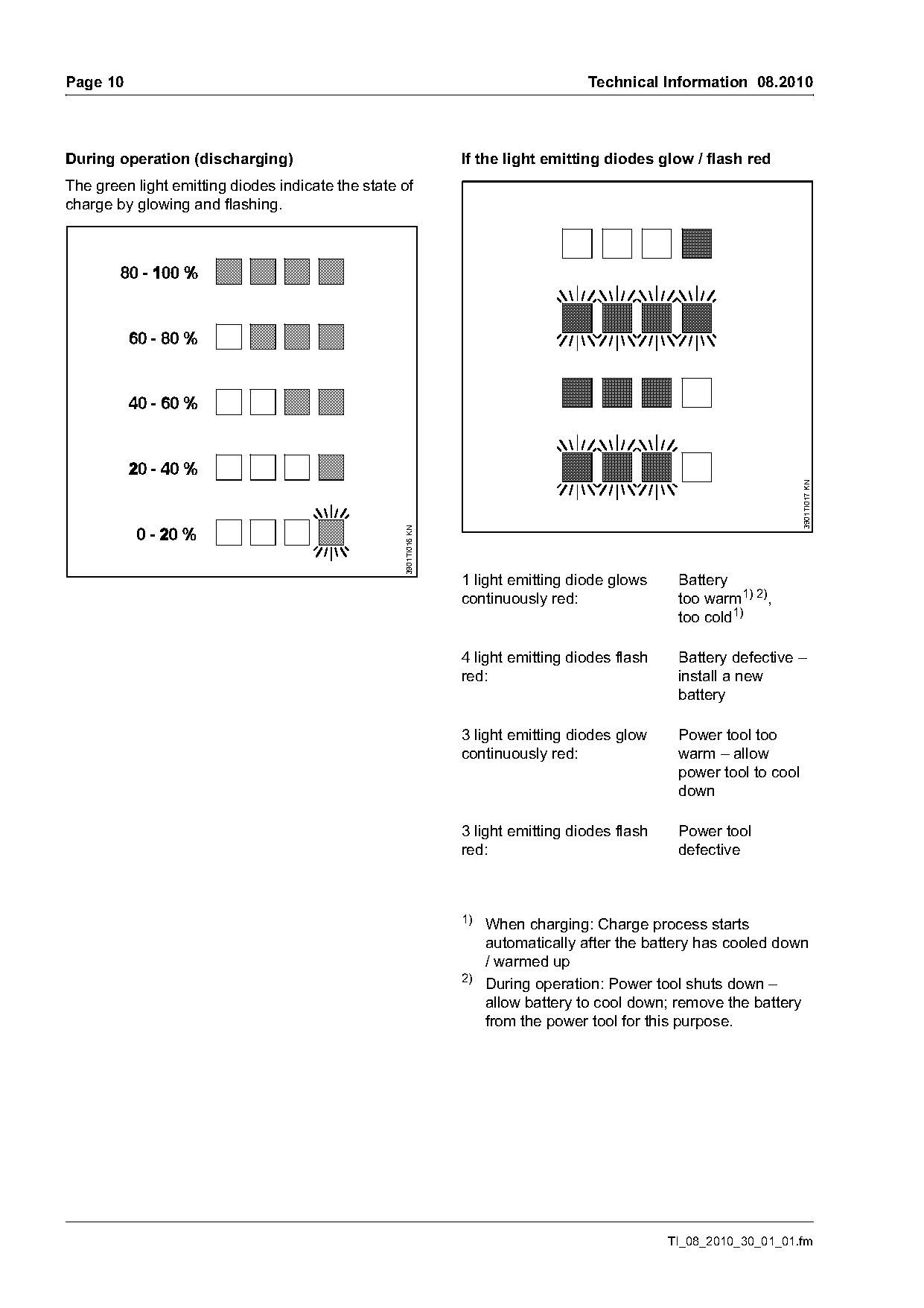
During operation (discharging)                                    If the light emitting diodes glow / flash red
The green light emitting diodes indicate the state of
charge by glowing and flashing.

                                                                                                                        3901TI017 KN
                                                   3901TI016 KN

                                                                  1 light emitting diode glows     Battery
                                                                  continuously red:                too warm1) 2),
                                                                                                   too cold1)

                                                                  4 light emitting diodes flash    Battery defective –
                                                                  red:                             install a new
                                                                                                   battery

                                                                  3 light emitting diodes glow     Power tool too
                                                                  continuously red:                warm – allow
                                                                                                   power tool to cool
                                                                                                   down

                                                                  3 light emitting diodes flash    Power tool
                                                                  red:                             defective

                                                                  1)
                                                                       When charging: Charge process starts
                                                                       automatically after the battery has cooled down
                                                                       / warmed up
                                                                  2)
                                                                       During operation: Power tool shuts down –
                                                                       allow battery to cool down; remove the battery
                                                                       from the power tool for this purpose.

                                                                                                  TI_08_2010_30_01_01.fm
Page 11 of 18
Text of page 11 — search, copy, screen readers
Technical Information 08.2010                                                                         Page 11

3.7.4   Storing the battery                              3.7.7    Battery recycling
.   Remove the battery from the machine or the           Battery recycling information:
    charger.
.   Store in a safe, dry and locked location. Keep
    out of the reach of children and other
    unauthorized persons and protected from
    contamination.
.   Do not store spare batteries unused – use in
    rotation.
To ensure maximum battery life:
.   Store at temperatures between 50°F (10°C) and
    70°F (20°C)
.   Store with a charge of about 30%.
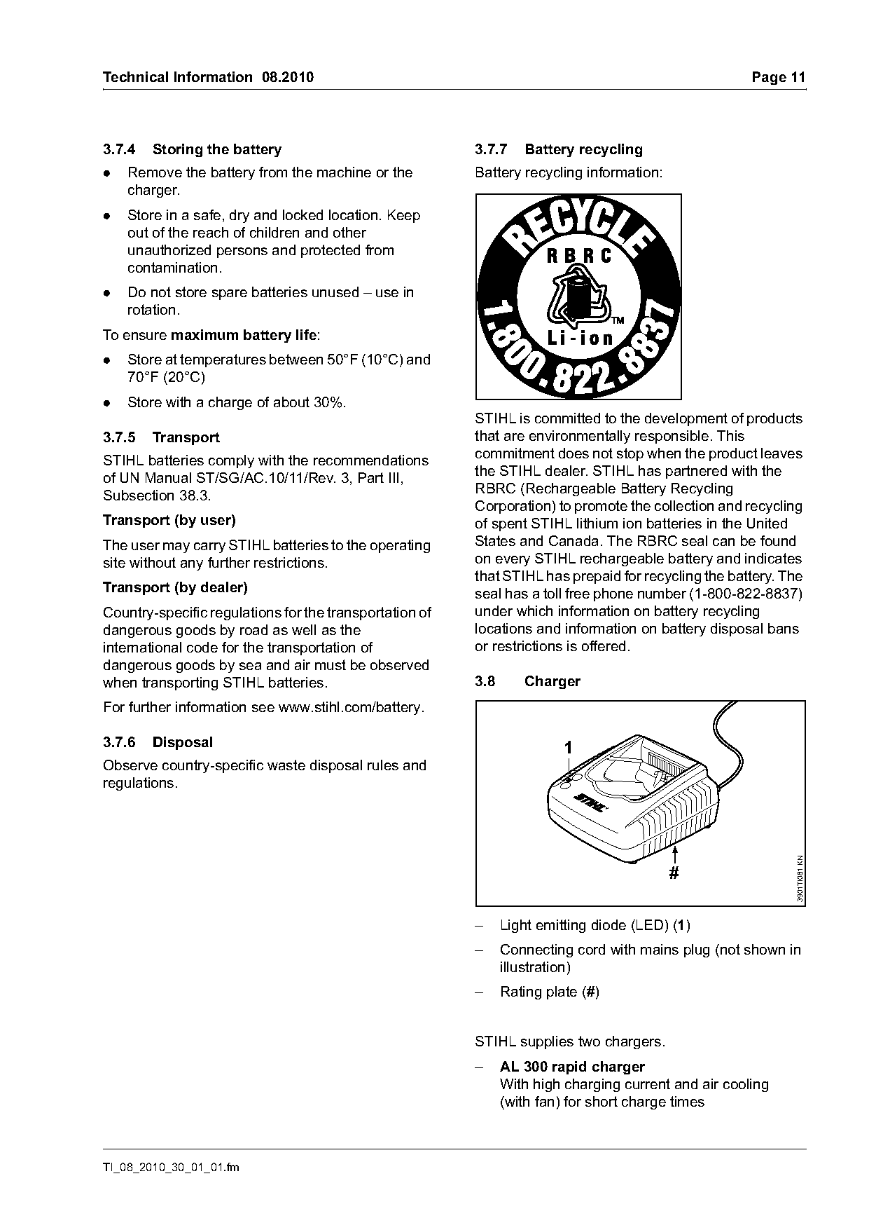
                                                         STIHL is committed to the development of products
3.7.5   Transport                                        that are environmentally responsible. This
STIHL batteries comply with the recommendations          commitment does not stop when the product leaves
of UN Manual ST/SG/AC.10/11/Rev. 3, Part III,            the STIHL dealer. STIHL has partnered with the
Subsection 38.3.                                         RBRC (Rechargeable Battery Recycling
                                                         Corporation) to promote the collection and recycling
Transport (by user)                                      of spent STIHL lithium ion batteries in the United
The user may carry STIHL batteries to the operating      States and Canada. The RBRC seal can be found
site without any further restrictions.                   on every STIHL rechargeable battery and indicates
                                                         that STIHL has prepaid for recycling the battery. The
Transport (by dealer)                                    seal has a toll free phone number (1-800-822-8837)
Country-specific regulations for the transportation of   under which information on battery recycling
dangerous goods by road as well as the                   locations and information on battery disposal bans
international code for the transportation of             or restrictions is offered.
dangerous goods by sea and air must be observed
when transporting STIHL batteries.                       3.8      Charger
For further information see www.stihl.com/battery.

3.7.6   Disposal                                                         1
Observe country-specific waste disposal rules and
regulations.
                                                                                                            3901TI081 KN

                                                                                          #

                                                         –     Light emitting diode (LED) (1)
                                                         –     Connecting cord with mains plug (not shown in
                                                               illustration)
                                                         –     Rating plate (#)

                                                         STIHL supplies two chargers.
                                                         –     AL 300 rapid charger
                                                               With high charging current and air cooling
                                                               (with fan) for short charge times

TI_08_2010_30_01_01.fm
Page 12 of 18
Text of page 12 — search, copy, screen readers
Page 12                                                                                  Technical Information 08.2010

–   AL 100 rapid charger
    With low charging current and no air cooling
    (no fan)

Charging principle
The charger charges the battery in two stages. The
battery is first charged at a constant current up to a
preset voltage limit. The charger then switches over

                                                                                                                            3901TI020 KN
to charging at a constant voltage. The charge
current is reduced automatically until it drops below
                                                                                   3           4
a given minimum or the preset total charge time is
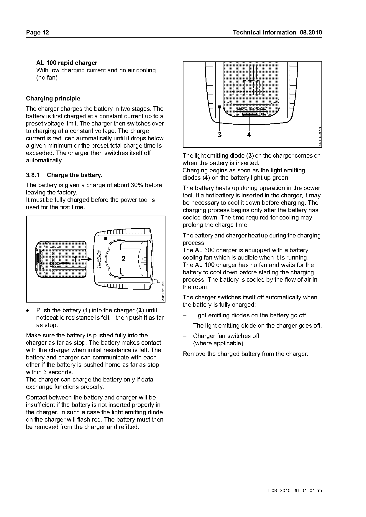
exceeded. The charger then switches itself off                       The light emitting diode (3) on the charger comes on
automatically.                                                       when the battery is inserted.
                                                                     Charging begins as soon as the light emitting
3.8.1   Charge the battery.                                          diodes (4) on the battery light up green.
The battery is given a charge of about 30% before
                                                                     The battery heats up during operation in the power
leaving the factory.
                                                                     tool. If a hot battery is inserted in the charger, it may
It must be fully charged before the power tool is
                                                                     be necessary to cool it down before charging. The
used for the first time.
                                                                     charging process begins only after the battery has
                                                                     cooled down. The time required for cooling may
                                                                     prolong the charge time.
                                                                     The battery and charger heat up during the charging
                                                                     process.
                                                                     The AL 300 charger is equipped with a battery
                                      2                              cooling fan which is audible when it is running.
                                                                     The AL 100 charger has no fan and waits for the
                                                                     battery to cool down before starting the charging
                                                                     process. The battery is cooled by the flow of air in
                                                      3901TI019 KN

                                                                     the room.
                                                                     The charger switches itself off automatically when
                                                                     the battery is fully charged:
.   Push the battery (1) into the charger (2) until
    noticeable resistance is felt – then push it as far              –   Light emitting diodes on the battery go off.
    as stop.                                                         –   The light emitting diode on the charger goes off.
Make sure the battery is pushed fully into the                       –   Charger fan switches off
charger as far as stop. The battery makes contact                        (where applicable).
with the charger when initial resistance is felt. The
                                                                     Remove the charged battery from the charger.
battery and charger can communicate with each
other if the battery is pushed home as far as stop
within 3 seconds.
The charger can charge the battery only if data
exchange functions properly.
Contact between the battery and charger will be
insufficient if the battery is not inserted properly in
the charger. In such a case the light emitting diode
on the charger will flash red. The battery must then
be removed from the charger and refitted.

                                                                                                      TI_08_2010_30_01_01.fm
Page 13 of 18
Text of page 13 — search, copy, screen readers
Technical Information 08.2010                                                                                      Page 13

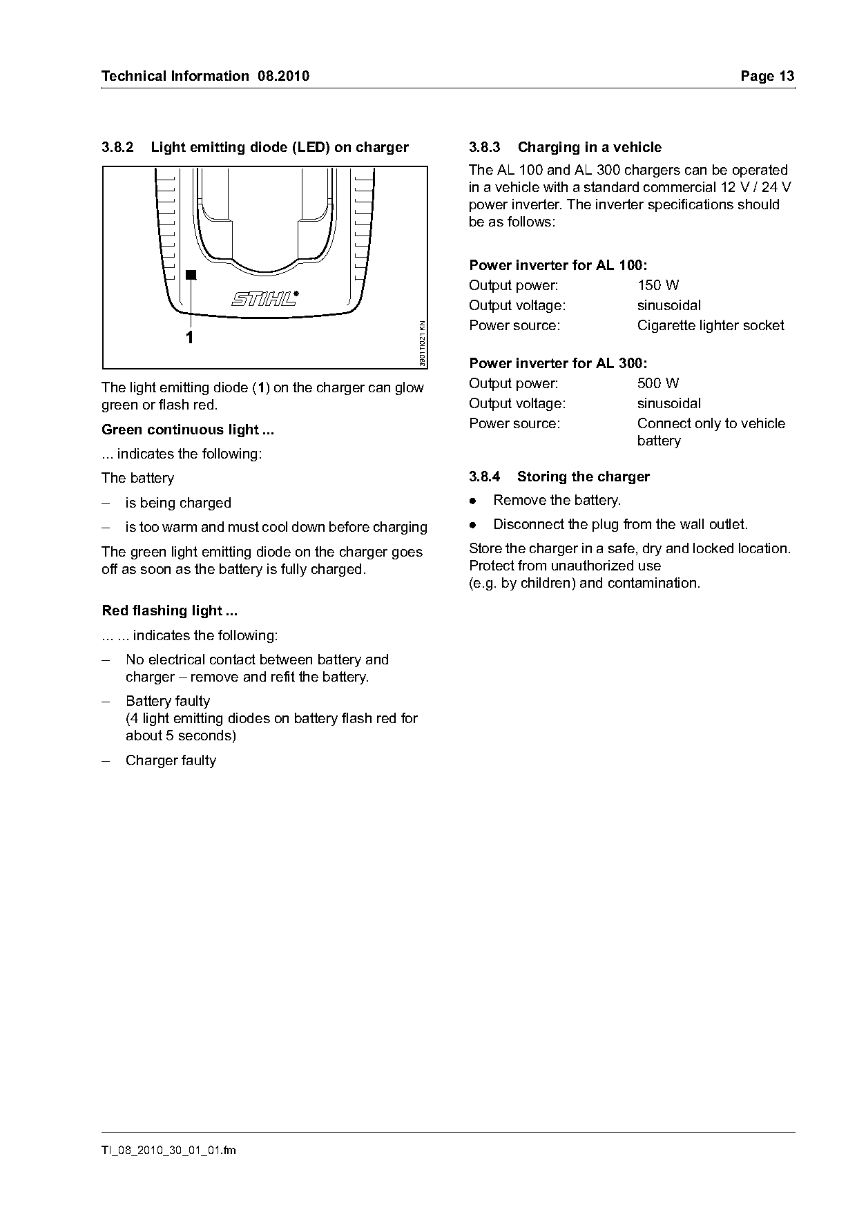
3.8.2   Light emitting diode (LED) on charger                          3.8.3   Charging in a vehicle
                                                                       The AL 100 and AL 300 chargers can be operated
                                                                       in a vehicle with a standard commercial 12 V / 24 V
                                                                       power inverter. The inverter specifications should
                                                                       be as follows:

                                                                       Power inverter for AL 100:
                                                                       Output power:           150 W
                                                                       Output voltage:         sinusoidal
                                                                       Power source:           Cigarette lighter socket

                                                        3901TI021 KN
               1
                                                                       Power inverter for AL 300:
The light emitting diode (1) on the charger can glow                   Output power:           500 W
green or flash red.                                                    Output voltage:         sinusoidal
Green continuous light ...                                             Power source:           Connect only to vehicle
                                                                                               battery
... indicates the following:
The battery                                                            3.8.4   Storing the charger
–   is being charged                                                   .   Remove the battery.
–   is too warm and must cool down before charging                     .   Disconnect the plug from the wall outlet.
The green light emitting diode on the charger goes                     Store the charger in a safe, dry and locked location.
off as soon as the battery is fully charged.                           Protect from unauthorized use
                                                                       (e.g. by children) and contamination.
Red flashing light ...
... ... indicates the following:
–   No electrical contact between battery and
    charger – remove and refit the battery.
–   Battery faulty
    (4 light emitting diodes on battery flash red for
    about 5 seconds)
–   Charger faulty

TI_08_2010_30_01_01.fm
Page 14 of 18
Text of page 14 — search, copy, screen readers
Page 14                                                                   Technical Information 08.2010

4.     Specifications                                 4.4     Gearhead
                                                      Stroke rate (off load):    3,000/min
4.1    Battery                                        STIHL multipurpose
AP 80                                                 grease
Type:                      Lithium-Ion                – 80 g tube                0781 120 1109
Rated voltage:             36 V                       – 225 g tube               0781 120 1110
Capacity:                  2.2 Ah                     Initial capacity:          0.7 oz (20 g)
                                                      Re-lubrication:            see b 9.3

                                                      4.5     Weight
4.2    Charger
                                                      Without battery, with cutting attachment, without
AL 100
                                                      blade scabbard
Power supply:              120 V
                                                      – HSA 65:                   7.9lbs (3.6 kg)
Rated current:             1.3 A
Frequency:                 60 Hz
Wattage:                   75 W
Charge current:            1.6 A
Charge time (for AP 80):
– up to 80% capacity:      70 min
– up to 100% capacity:     100 min
Insulation:                II, E (double insulated)

AL 300
Power supply:              120 V
Rated current:             4.7 A
Frequency:                 60 Hz
Wattage:                   330 W
Charge current:            6.5 A
Charge time (for AP 80):
– up to 80% capacity:      25 min
– up to 100% capacity:     50 min
Insulation:                II, E (double insulated)

4.3    Cutting Attachment
Cutting length:            20“ (500 mm)
Tooth spacing:             1.1 in (26.5 mm)
Sharpening angle
from horizontal:           40°

                                                                                    TI_08_2010_30_01_01.fm
Page 15 of 18
Text of page 15 — search, copy, screen readers
Technical Information 08.2010                                       Page 15

5.       Cutting Attachment

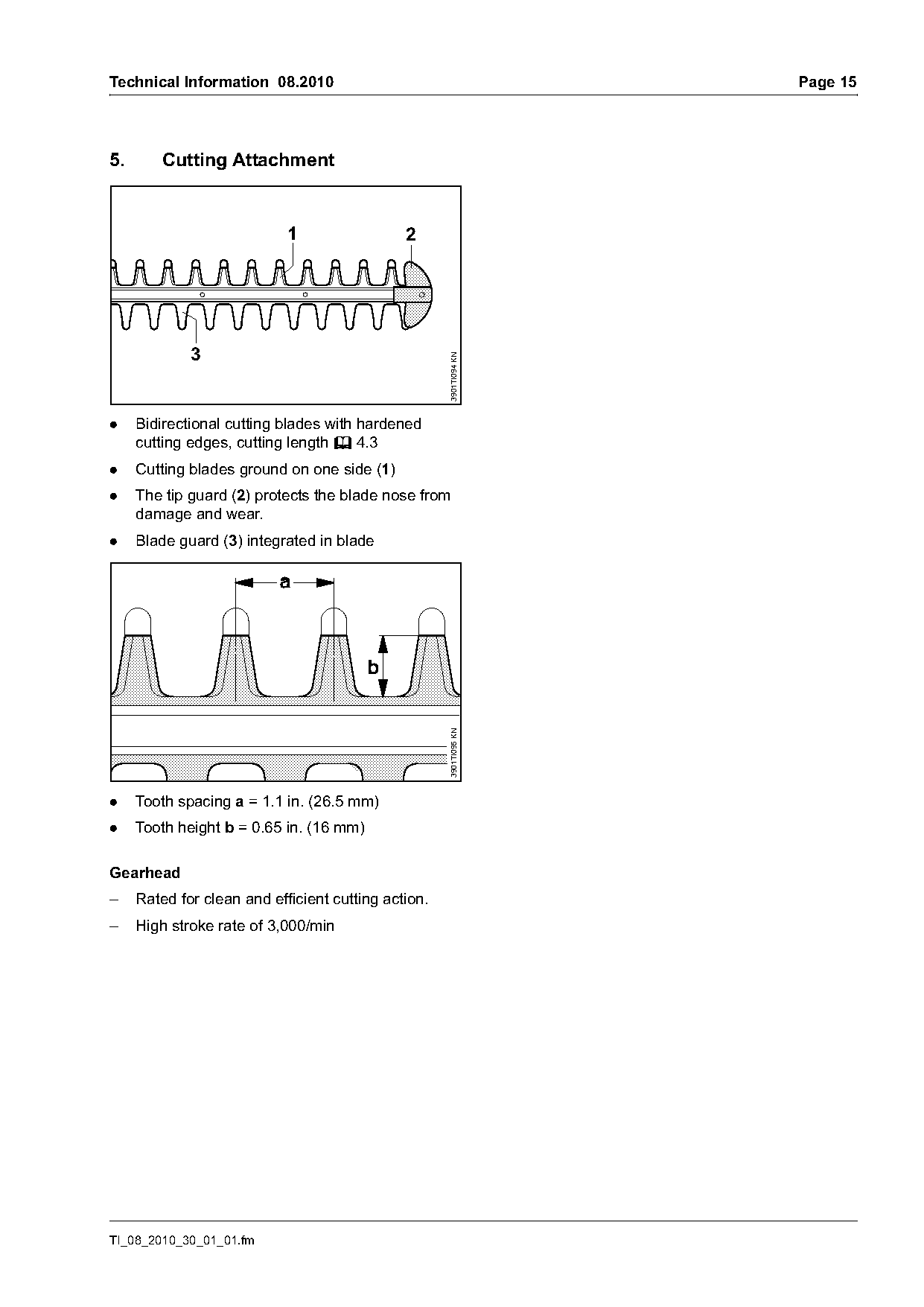
                            1                 2


                                                     3901TI094 KN
.    Bidirectional cutting blades with hardened
     cutting edges, cutting length b 4.3
.    Cutting blades ground on one side (1)
.    The tip guard (2) protects the blade nose from
     damage and wear.
.    Blade guard (3) integrated in blade
                                                     3901TI095 KN

.    Tooth spacing a = 1.1 in. (26.5 mm)
.    Tooth height b = 0.65 in. (16 mm)

Gearhead
–    Rated for clean and efficient cutting action.
–    High stroke rate of 3,000/min

TI_08_2010_30_01_01.fm
Page 16 of 18
Text of page 16 — search, copy, screen readers
Page 16                                                                    Technical Information 08.2010

6.     Special Accessory
Description                      Part No.                        Application
STIHL battery:
– AP 80:                         4850 400 6503
STIHL charger:                                                   Charging the battery.
– AL 100:                        4850 430 2502
– AL 300:                        4850 430 5502
STIHL resin solvent:                                             Cleaning and lubricating blades
(300 ml can)                     0782 420 1002                   (before and after work)
Blade scabbard:                  4812 790 9200                   HSA 65, cutting length 20" (500 mm)

7.     Servicing Accessories

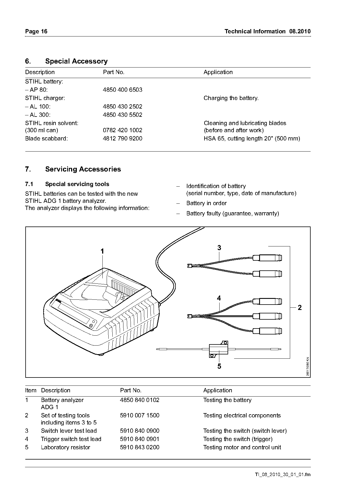
7.1    Special servicing tools                         –   Identification of battery
STIHL batteries can be tested with the new                 (serial number, type, date of manufacture)
STIHL ADG 1 battery analyzer.                          –   Battery in order
The analyzer displays the following information:
                                                       –   Battery faulty (guarantee, warranty)

                             1                                         3

                                                                       4
                                                                                                        2   3901TI080 KN


Item Description                       Part No.                  Application
1     Battery analyzer                 4850 840 0102             Testing the battery
      ADG 1
2     Set of testing tools             5910 007 1500             Testing electrical components
      including items 3 to 5
3     Switch lever test lead           5910 840 0900             Testing the switch (switch lever)
4     Trigger switch test lead         5910 840 0901             Testing the switch (trigger)
5     Laboratory resistor              5910 843 0200             Testing motor and control unit

                                                                                       TI_08_2010_30_01_01.fm
Page 17 of 18
Text of page 17 — search, copy, screen readers
Technical Information 08.2010                                                                                        Page 17

7.2     Servicing aids

                                                         3901TI025 KN
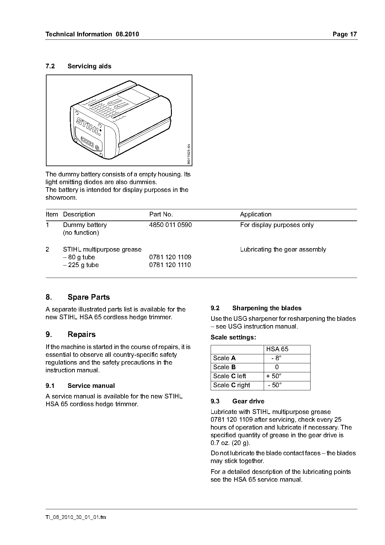
The dummy battery consists of a empty housing. Its
light emitting diodes are also dummies.
The battery is intended for display purposes in the
showroom.

Item Description                        Part No.                                  Application
1     Dummy battery                     4850 011 0590                             For display purposes only
      (no function)

2     STIHL multipurpose grease                                                   Lubricating the gear assembly
      – 80 g tube                       0781 120 1109
      – 225 g tube                      0781 120 1110

8.      Spare Parts
A separate illustrated parts list is available for the                  9.2     Sharpening the blades
new STIHL HSA 65 cordless hedge trimmer.                                Use the USG sharpener for resharpening the blades
                                                                        – see USG instruction manual.
9.      Repairs                                                         Scale settings:
If the machine is started in the course of repairs, it is                                    HSA 65
essential to observe all country-specific safety                        Scale A                - 8°
regulations and the safety precautions in the
                                                                        Scale B                  0
instruction manual.
                                                                        Scale C left         + 50°
9.1     Service manual                                                  Scale C right        - 50°
A service manual is available for the new STIHL
HSA 65 cordless hedge trimmer.                                          9.3     Gear drive
                                                                        Lubricate with STIHL multipurpose grease
                                                                        0781 120 1109 after servicing, check every 25
                                                                        hours of operation and lubricate if necessary. The
                                                                        specified quantity of grease in the gear drive is
                                                                        0.7 oz. (20 g).
                                                                        Do not lubricate the blade contact faces – the blades
                                                                        may stick together.
                                                                        For a detailed description of the lubricating points
                                                                        see the HSA 65 service manual.

TI_08_2010_30_01_01.fm
Page 18 of 18
Text of page 18 — search, copy, screen readers
Page 18                                                                            Technical Information 08.2010

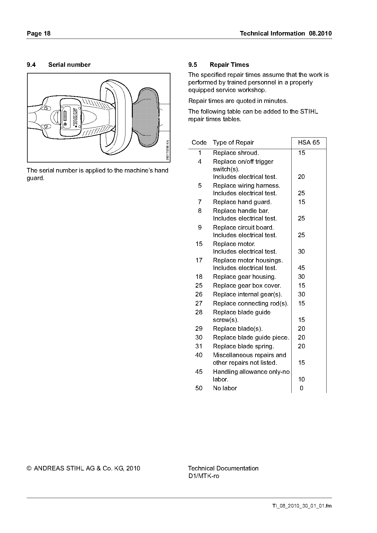
9.4    Serial number                                            9.5       Repair Times
                                                                The specified repair times assume that the work is
                                                                performed by trained personnel in a properly
                                                                equipped service workshop.
                                                                Repair times are quoted in minutes.
                                                                The following table can be added to the STIHL
                                                                repair times tables.

                                                                 Code Type of Repair                   HSA 65

                                                 3901TI098 KN
                                                                      1   Replace shroud.              15
                                                                      4   Replace on/off trigger
The serial number is applied to the machine’s hand                        switch(s).
guard.                                                                    Includes electrical test.    20
                                                                      5   Replace wiring harness.
                                                                          Includes electrical test.    25
                                                                      7   Replace hand guard.          15
                                                                      8   Replace handle bar.
                                                                          Includes electrical test.    25
                                                                      9   Replace circuit board.
                                                                          Includes electrical test.    25
                                                                  15      Replace motor.
                                                                          Includes electrical test.    30
                                                                  17      Replace motor housings.
                                                                          Includes electrical test.    45
                                                                  18      Replace gear housing.        30
                                                                  25      Replace gear box cover.      15
                                                                  26      Replace internal gear(s).    30
                                                                  27      Replace connecting rod(s).   15
                                                                  28      Replace blade guide
                                                                          screw(s).                    15
                                                                  29      Replace blade(s).            20
                                                                  30      Replace blade guide piece.   20
                                                                  31      Replace blade spring.        20
                                                                  40      Miscellaneous repairs and
                                                                          other repairs not listed.    15
                                                                  45      Handling allowance only-no
                                                                          labor.                       10
                                                                  50      No labor                     0

© ANDREAS STIHL AG & Co. KG, 2010                               Technical Documentation
                                                                D1/MTK-ro

                                                                                              TI_08_2010_30_01_01.fm
Most of these PDFs embed fonts with a shifted character map, so the text above was recovered rather than copied — read it as a faithful but imperfect transcription, and treat the page image above each block as the authority where the two disagree — the figures exist only there, because they are vector drawings that text extraction cannot keep.