Technical Information · issue 11 of 2010
Carburetor; Fuel Tank with 2 Pickup Bodies; Blowing Attachment; Chest Strap
IssueTI 11/2010
Full text
Page 1 of 12
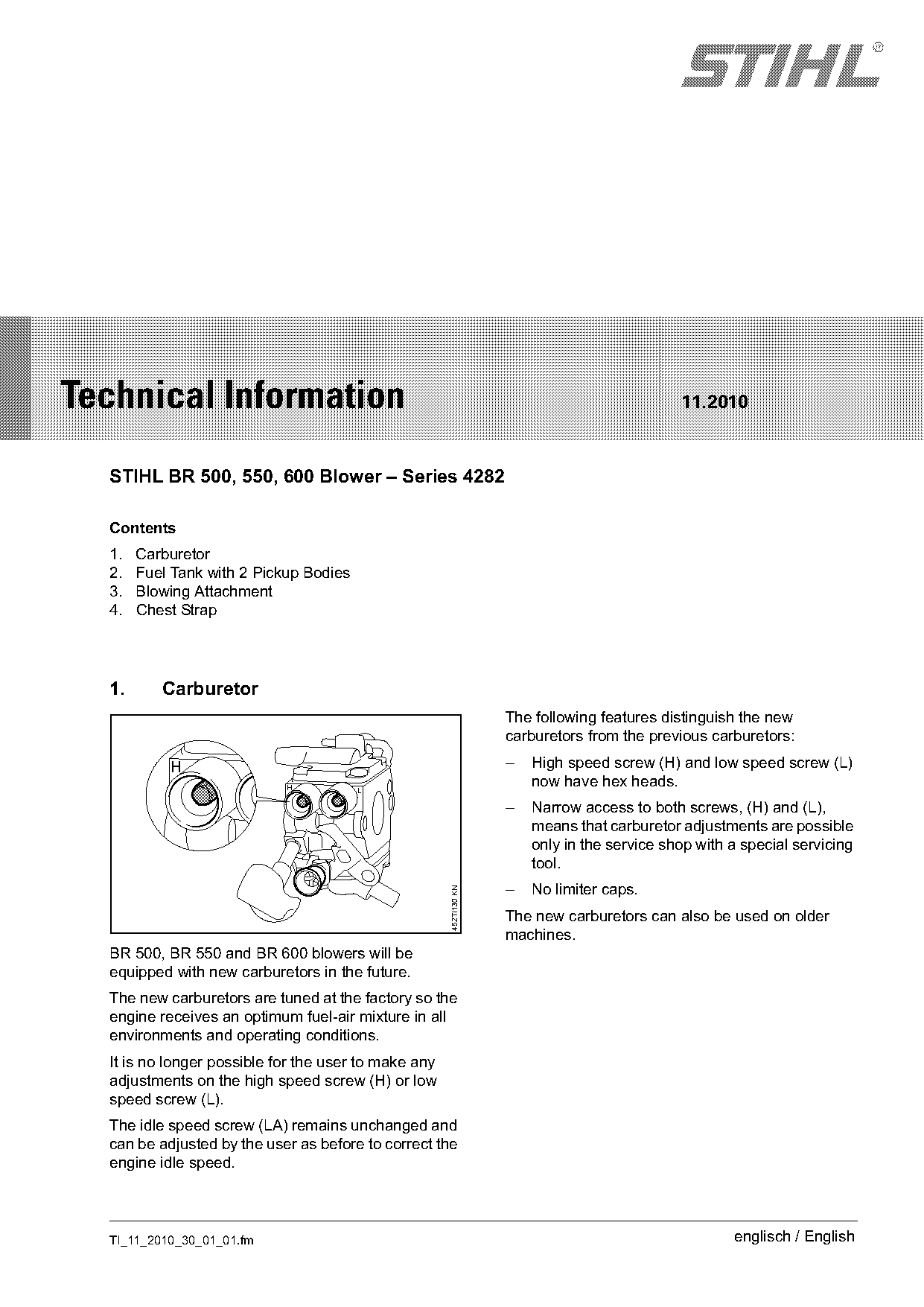
Text of page 1 — search, copy, screen readers
STIH)

Technical Information                                                                         11.2010

  STIHL BR 500, 550, 600 Blower – Series 4282

  Contents
  1.   Carburetor
  2.   Fuel Tank with 2 Pickup Bodies
  3.   Blowing Attachment
  4.   Chest Strap

  1.      Carburetor
                                                                    The following features distinguish the new
                                                                    carburetors from the previous carburetors:

           H                                                        –   High speed screw (H) and low speed screw (L)
                            H           L
                                                                        now have hex heads.
                                                                    –   Narrow access to both screws, (H) and (L),
                                                                        means that carburetor adjustments are possible
                                                                        only in the service shop with a special servicing
                                                                        tool.
                                                                    –   No limiter caps.
                                                      452TI130 KN

                                                                    The new carburetors can also be used on older
                                                                    machines.
  BR 500, BR 550 and BR 600 blowers will be
  equipped with new carburetors in the future.
  The new carburetors are tuned at the factory so the
  engine receives an optimum fuel-air mixture in all
  environments and operating conditions.
  It is no longer possible for the user to make any
  adjustments on the high speed screw (H) or low
  speed screw (L).
  The idle speed screw (LA) remains unchanged and
  can be adjusted by the user as before to correct the
  engine idle speed.

  TI_11_2010_30_01_01.fm                                                                              englisch / English
Page 2 of 12
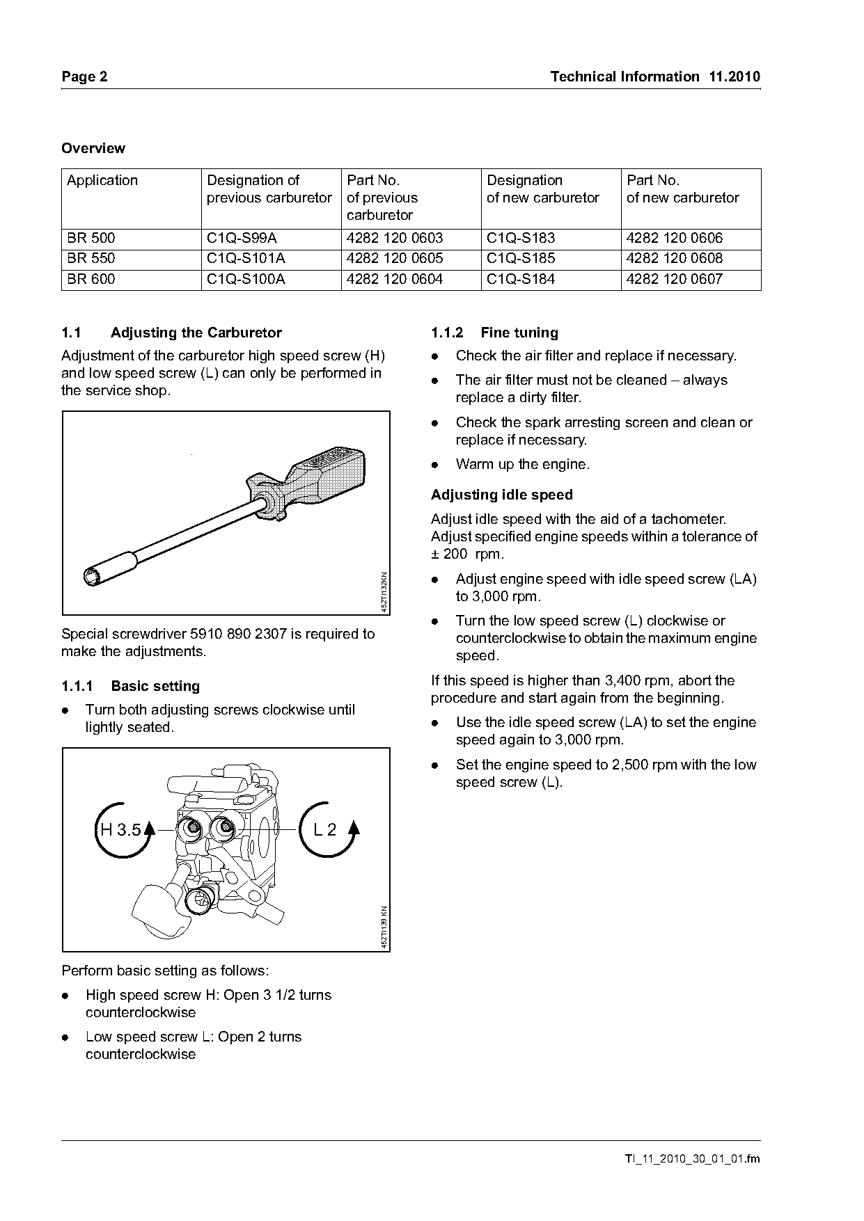
Text of page 2 — search, copy, screen readers
Page 2                                                                               Technical Information 11.2010

Overview

Application              Designation of        Part No.                    Designation           Part No.
                         previous carburetor   of previous                 of new carburetor     of new carburetor
                                               carburetor
BR 500                   C1Q-S99A              4282 120 0603               C1Q-S183              4282 120 0606
BR 550                   C1Q-S101A             4282 120 0605               C1Q-S185              4282 120 0608
BR 600                   C1Q-S100A             4282 120 0604               C1Q-S184              4282 120 0607

1.1      Adjusting the Carburetor                                 1.1.2   Fine tuning
Adjustment of the carburetor high speed screw (H)                 .   Check the air filter and replace if necessary.
and low speed screw (L) can only be performed in                  .   The air filter must not be cleaned – always
the service shop.                                                     replace a dirty filter.
                                                                  .   Check the spark arresting screen and clean or
                                                                      replace if necessary.
                                                                  .   Warm up the engine.

                                                                  Adjusting idle speed
                                                                  Adjust idle speed with the aid of a tachometer.
                                                                  Adjust specified engine speeds within a tolerance of
                                                                  ± 200 rpm.
                                                                  .   Adjust engine speed with idle speed screw (LA)
                                                    452TI132KN

                                                                      to 3,000 rpm.
                                                                  .   Turn the low speed screw (L) clockwise or
Special screwdriver 5910 890 2307 is required to                      counterclockwise to obtain the maximum engine
make the adjustments.                                                 speed.

1.1.1    Basic setting                                            If this speed is higher than 3,400 rpm, abort the
                                                                  procedure and start again from the beginning.
.     Turn both adjusting screws clockwise until
      lightly seated.                                             .   Use the idle speed screw (LA) to set the engine
                                                                      speed again to 3,000 rpm.
                                                                  .   Set the engine speed to 2,500 rpm with the low
                                                                      speed screw (L).

                    H         L

        H 3.5                            L2
                                                    452TI139 KN

Perform basic setting as follows:
.     High speed screw H: Open 3 1/2 turns
      counterclockwise
.     Low speed screw L: Open 2 turns
      counterclockwise

                                                                                                 TI_11_2010_30_01_01.fm
Page 3 of 12
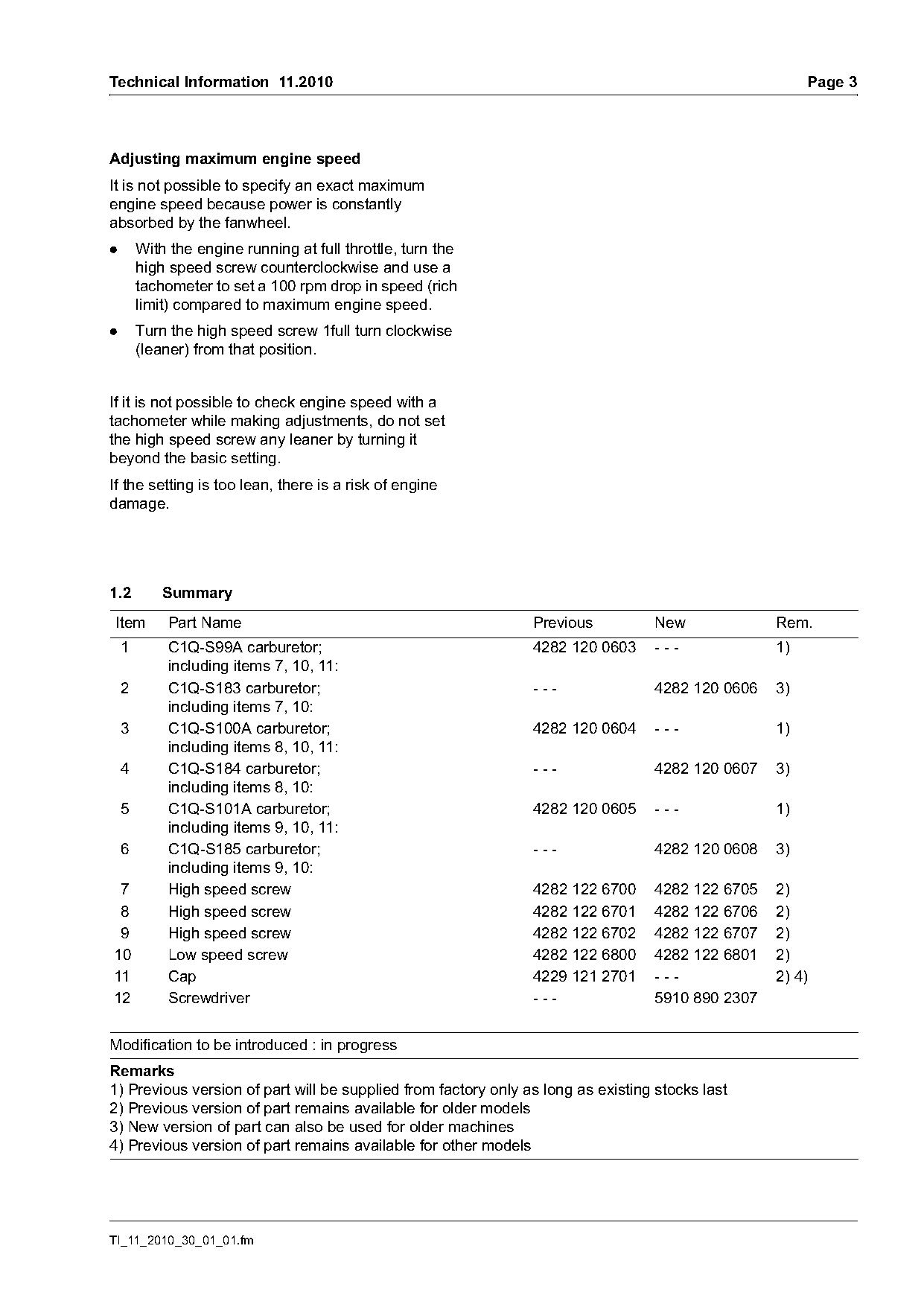
Text of page 3 — search, copy, screen readers
Technical Information 11.2010                                                                          Page 3

Adjusting maximum engine speed
It is not possible to specify an exact maximum
engine speed because power is constantly
absorbed by the fanwheel.
.       With the engine running at full throttle, turn the
        high speed screw counterclockwise and use a
        tachometer to set a 100 rpm drop in speed (rich
        limit) compared to maximum engine speed.
.       Turn the high speed screw 1full turn clockwise
        (leaner) from that position.

If it is not possible to check engine speed with a
tachometer while making adjustments, do not set
the high speed screw any leaner by turning it
beyond the basic setting.
If the setting is too lean, there is a risk of engine
damage.

1.2         Summary
Item         Part Name                                          Previous          New             Rem.
    1        C1Q-S99A carburetor;                               4282 120 0603     ---             1)
             including items 7, 10, 11:
    2        C1Q-S183 carburetor;                               ---               4282 120 0606   3)
             including items 7, 10:
    3        C1Q-S100A carburetor;                              4282 120 0604     ---             1)
             including items 8, 10, 11:
    4        C1Q-S184 carburetor;                               ---               4282 120 0607   3)
             including items 8, 10:
    5        C1Q-S101A carburetor;                              4282 120 0605     ---             1)
             including items 9, 10, 11:
    6        C1Q-S185 carburetor;                               ---               4282 120 0608   3)
             including items 9, 10:
 7           High speed screw                                   4282 122 6700     4282 122 6705   2)
 8           High speed screw                                   4282 122 6701     4282 122 6706   2)
 9           High speed screw                                   4282 122 6702     4282 122 6707   2)
10           Low speed screw                                    4282 122 6800     4282 122 6801   2)
11           Cap                                                4229 121 2701     ---             2) 4)
12           Screwdriver                                        ---               5910 890 2307

Modification to be introduced : in progress
Remarks
1) Previous version of part will be supplied from factory only as long as existing stocks last
2) Previous version of part remains available for older models
3) New version of part can also be used for older machines
4) Previous version of part remains available for other models

TI_11_2010_30_01_01.fm
Page 4 of 12
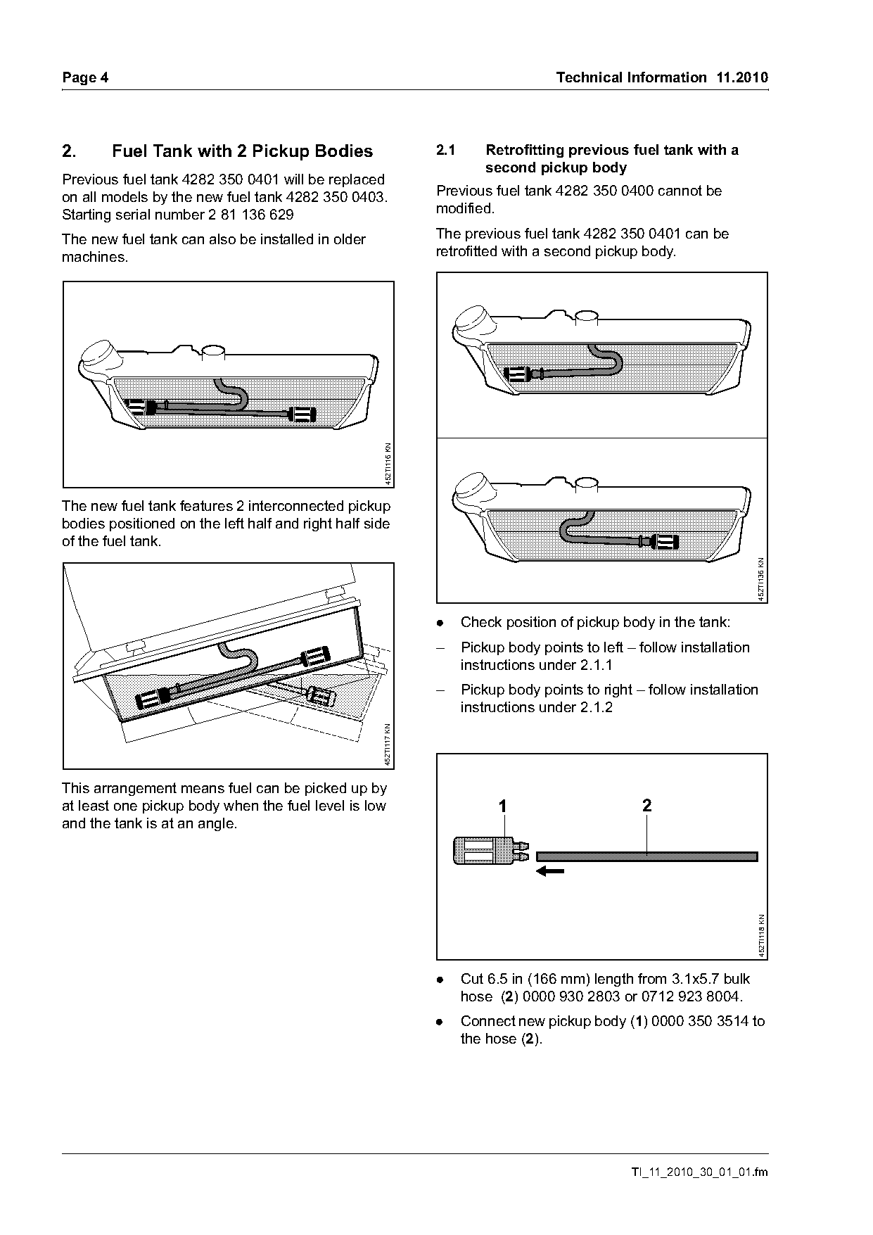
Text of page 4 — search, copy, screen readers
Page 4                                                                                  Technical Information 11.2010

2.       Fuel Tank with 2 Pickup Bodies                            2.1       Retrofitting previous fuel tank with a
                                                                             second pickup body
Previous fuel tank 4282 350 0401 will be replaced
on all models by the new fuel tank 4282 350 0403.                  Previous fuel tank 4282 350 0400 cannot be
Starting serial number 2 81 136 629                                modified.

The new fuel tank can also be installed in older                   The previous fuel tank 4282 350 0401 can be
machines.                                                          retrofitted with a second pickup body.

                                                     452TI116 KN

The new fuel tank features 2 interconnected pickup
bodies positioned on the left half and right half side
of the fuel tank.

                                                                                                                            452TI136 KN
                                                                   .     Check position of pickup body in the tank:
                                                                   –     Pickup body points to left – follow installation
                                                                         instructions under 2.1.1
                                                                   –     Pickup body points to right – follow installation
                                                                         instructions under 2.1.2
                                                    452TI117 KN

This arrangement means fuel can be picked up by
at least one pickup body when the fuel level is low                            1                       2
and the tank is at an angle.
                                                                                                                             452TI118 KN

                                                                   .     Cut 6.5 in (166 mm) length from 3.1x5.7 bulk
                                                                         hose (2) 0000 930 2803 or 0712 923 8004.
                                                                   .     Connect new pickup body (1) 0000 350 3514 to
                                                                         the hose (2).

                                                                                                     TI_11_2010_30_01_01.fm
Page 5 of 12
Text of page 5 — search, copy, screen readers
Technical Information 11.2010                                                                                 Page 5

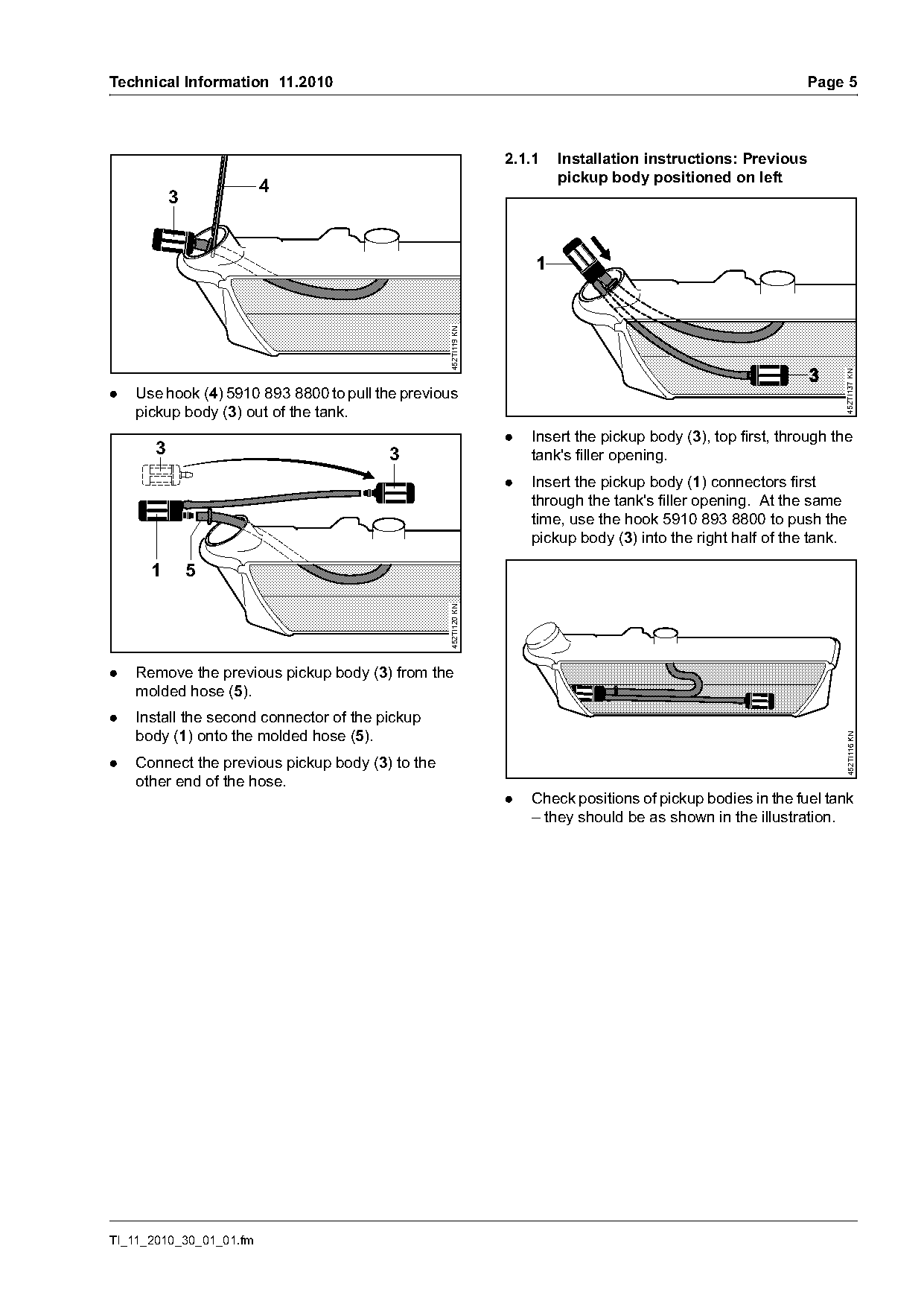
                                                                2.1.1   Installation instructions: Previous
                                                                        pickup body positioned on left
                         4
           3


                                                  452TI119 KN

                                                                                                                    452TI137 KN
.   Use hook (4) 5910 893 8800 to pull the previous
    pickup body (3) out of the tank.
                                                                .   Insert the pickup body (3), top first, through the
       3                                 3                          tank's filler opening.
                                                                .   Insert the pickup body (1) connectors first
                                                                    through the tank's filler opening. At the same
                                                                    time, use the hook 5910 893 8800 to push the
                                                                    pickup body (3) into the right half of the tank.

      1        5
                                                  452TI120 KN

.   Remove the previous pickup body (3) from the
    molded hose (5).
.   Install the second connector of the pickup
    body (1) onto the molded hose (5).

                                                                                                                     452TI116 KN
.   Connect the previous pickup body (3) to the
    other end of the hose.
                                                                .   Check positions of pickup bodies in the fuel tank
                                                                    – they should be as shown in the illustration.

TI_11_2010_30_01_01.fm
Page 6 of 12
Text of page 6 — search, copy, screen readers
Page 6                                                                               Technical Information 11.2010

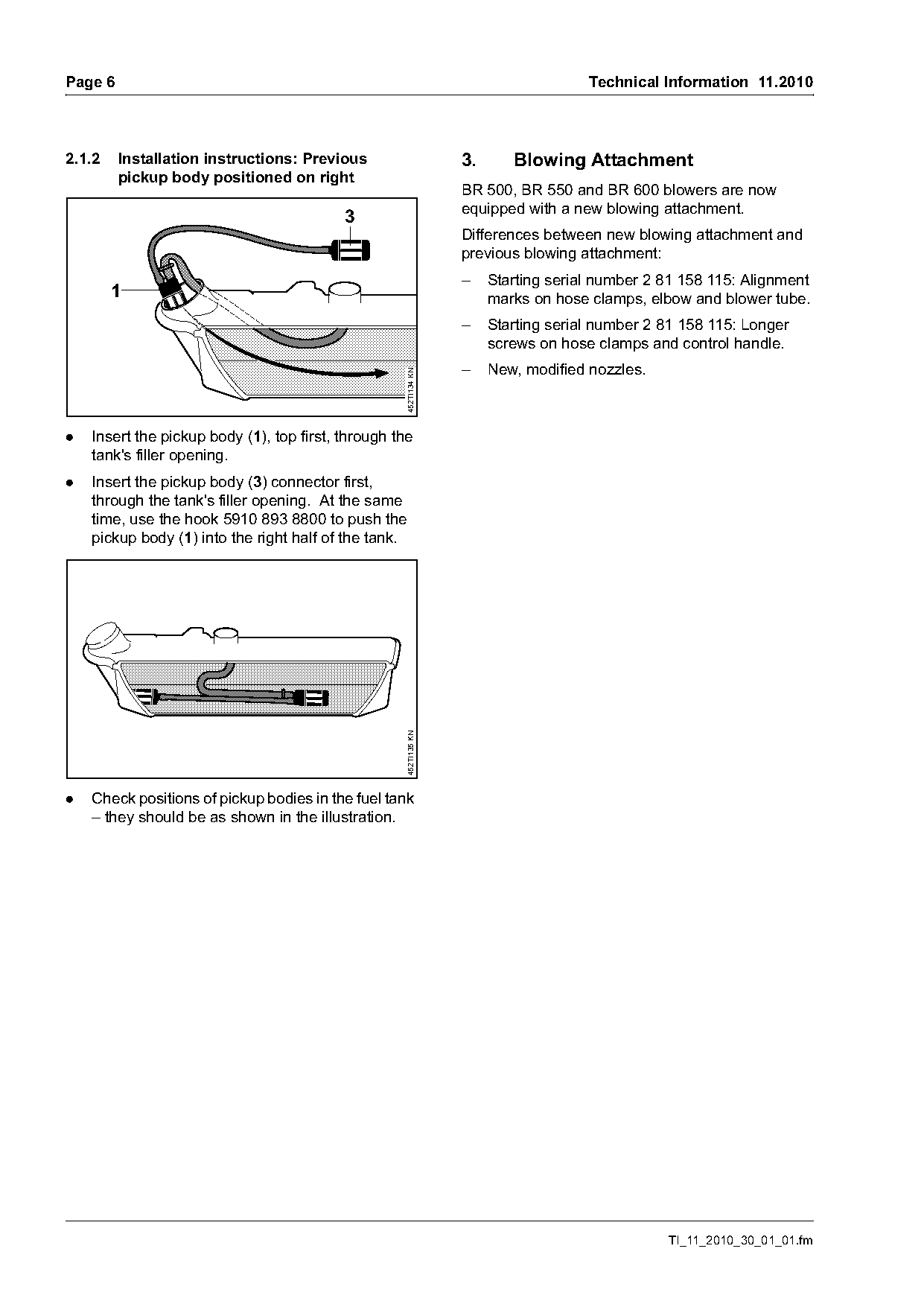
2.1.2    Installation instructions: Previous                      3.      Blowing Attachment
         pickup body positioned on right
                                                                  BR 500, BR 550 and BR 600 blowers are now
                                                                  equipped with a new blowing attachment.
                                           3
                                                                  Differences between new blowing attachment and
                                                                  previous blowing attachment:
                                                                  –    Starting serial number 2 81 158 115: Alignment
        1                                                              marks on hose clamps, elbow and blower tube.
                                                                  –    Starting serial number 2 81 158 115: Longer
                                                                       screws on hose clamps and control handle.
                                                                  –    New, modified nozzles.

                                                    452TI134 KN

.   Insert the pickup body (1), top first, through the
    tank's filler opening.
.   Insert the pickup body (3) connector first,
    through the tank's filler opening. At the same
    time, use the hook 5910 893 8800 to push the
    pickup body (1) into the right half of the tank.
                                                    452TI135 KN

.   Check positions of pickup bodies in the fuel tank
    – they should be as shown in the illustration.

                                                                                                TI_11_2010_30_01_01.fm
Page 7 of 12
Text of page 7 — search, copy, screen readers
Technical Information 11.2010                                                                                 Page 7

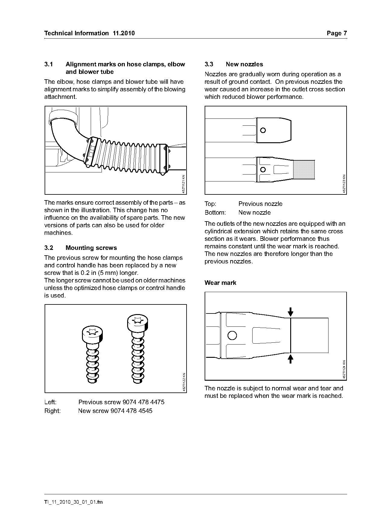
3.1      Alignment marks on hose clamps, elbow                    3.3    New nozzles
         and blower tube                                          Nozzles are gradually worn during operation as a
The elbow, hose clamps and blower tube will have                  result of ground contact. On previous nozzles the
alignment marks to simplify assembly of the blowing               wear caused an increase in the outlet cross section
attachment.                                                       which reduced blower performance.

                                                                                                                   452TI123 KN
                                                   452TI121 KN

The marks ensure correct assembly of the parts – as               Top:        Previous nozzle
shown in the illustration. This change has no                     Bottom:     New nozzle
influence on the availability of spare parts. The new
versions of parts can also be used for older                      The outlets of the new nozzles are equipped with an
machines.                                                         cylindrical extension which retains the same cross
                                                                  section as it wears. Blower performance thus
3.2      Mounting screws                                          remains constant until the wear mark is reached.
                                                                  The new nozzles are therefore longer than the
The previous screw for mounting the hose clamps
                                                                  previous nozzles.
and control handle has been replaced by a new
screw that is 0.2 in (5 mm) longer.
The longer screw cannot be used on older machines                 Wear mark
unless the optimized hose clamps or control handle
is used.

                                                                                                                   452TI124 KN
                                                    452TI122 KN

                                                                  The nozzle is subject to normal wear and tear and
                                                                  must be replaced when the wear mark is reached.
Left:       Previous screw 9074 478 4475
Right:      New screw 9074 478 4545

TI_11_2010_30_01_01.fm
Page 8 of 12
Text of page 8 — search, copy, screen readers
Page 8                                                             Technical Information 11.2010

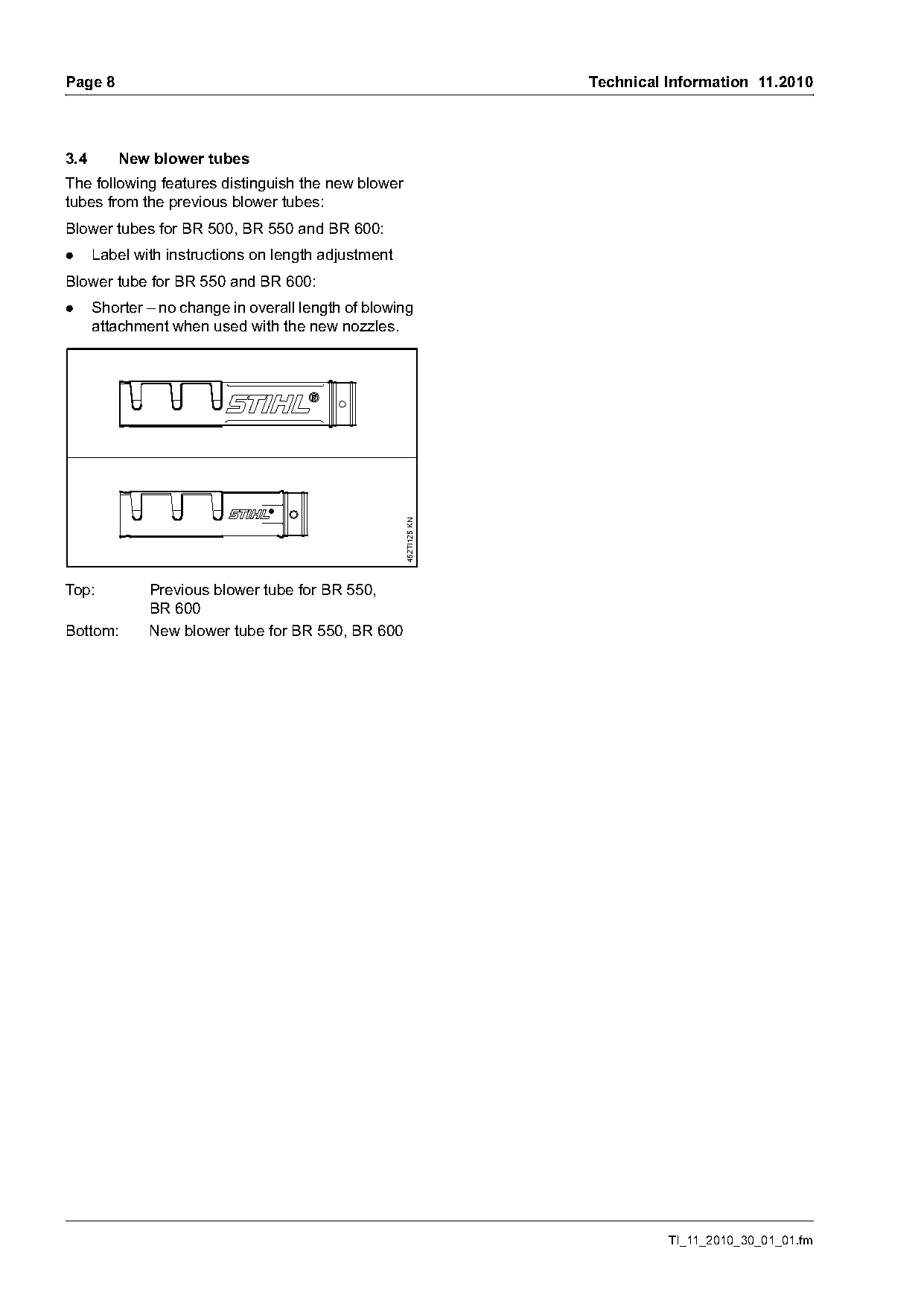
3.4      New blower tubes
The following features distinguish the new blower
tubes from the previous blower tubes:
Blower tubes for BR 500, BR 550 and BR 600:
.     Label with instructions on length adjustment
Blower tube for BR 550 and BR 600:
.     Shorter – no change in overall length of blowing
      attachment when used with the new nozzles.

                                                     452TI125 KN

Top:          Previous blower tube for BR 550,
              BR 600
Bottom:       New blower tube for BR 550, BR 600

                                                                             TI_11_2010_30_01_01.fm
Page 9 of 12
Text of page 9 — search, copy, screen readers
Technical Information 11.2010                                                                         Page 9

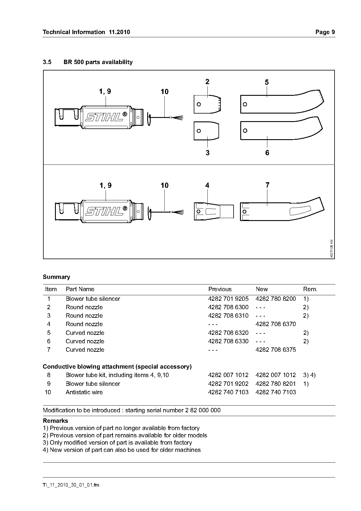
3.5     BR 500 parts availability

                                                             2                     5
                     1, 9                   10

                                                             3                      6

                         1, 9               10               4                      7

                                                                                                          452TI126 KN
Summary

Item    Part Name                                                Previous        New             Rem.
 1      Blower tube silencer                                     4282 701 9205   4282 780 8200   1)
 2      Round nozzle                                             4282 708 6300   ---             2)
 3      Round nozzle                                             4282 708 6310   ---             2)
 4      Round nozzle                                             ---             4282 708 6370
 5      Curved nozzle                                            4282 708 6320   ---             2)
 6      Curved nozzle                                            4282 708 6330   ---             2)
 7      Curved nozzle                                            ---             4282 708 6375

Conductive blowing attachment (special accessory)
 8    Blower tube kit, including items 4, 9,10                   4282 007 1012   4282 007 1012   3) 4)
 9    Blower tube silencer                                       4282 701 9202   4282 780 8201   1)
10    Antistatic wire                                            4282 740 7103   4282 740 7103

Modification to be introduced : starting serial number 2 82 000 000
Remarks
1) Previous version of part no longer available from factory
2) Previous version of part remains available for older models
3) Only modified version of part is available from factory
4) New version of part can also be used for older machines

TI_11_2010_30_01_01.fm
Page 10 of 12
Text of page 10 — search, copy, screen readers
Page 10                                                                         Technical Information 11.2010

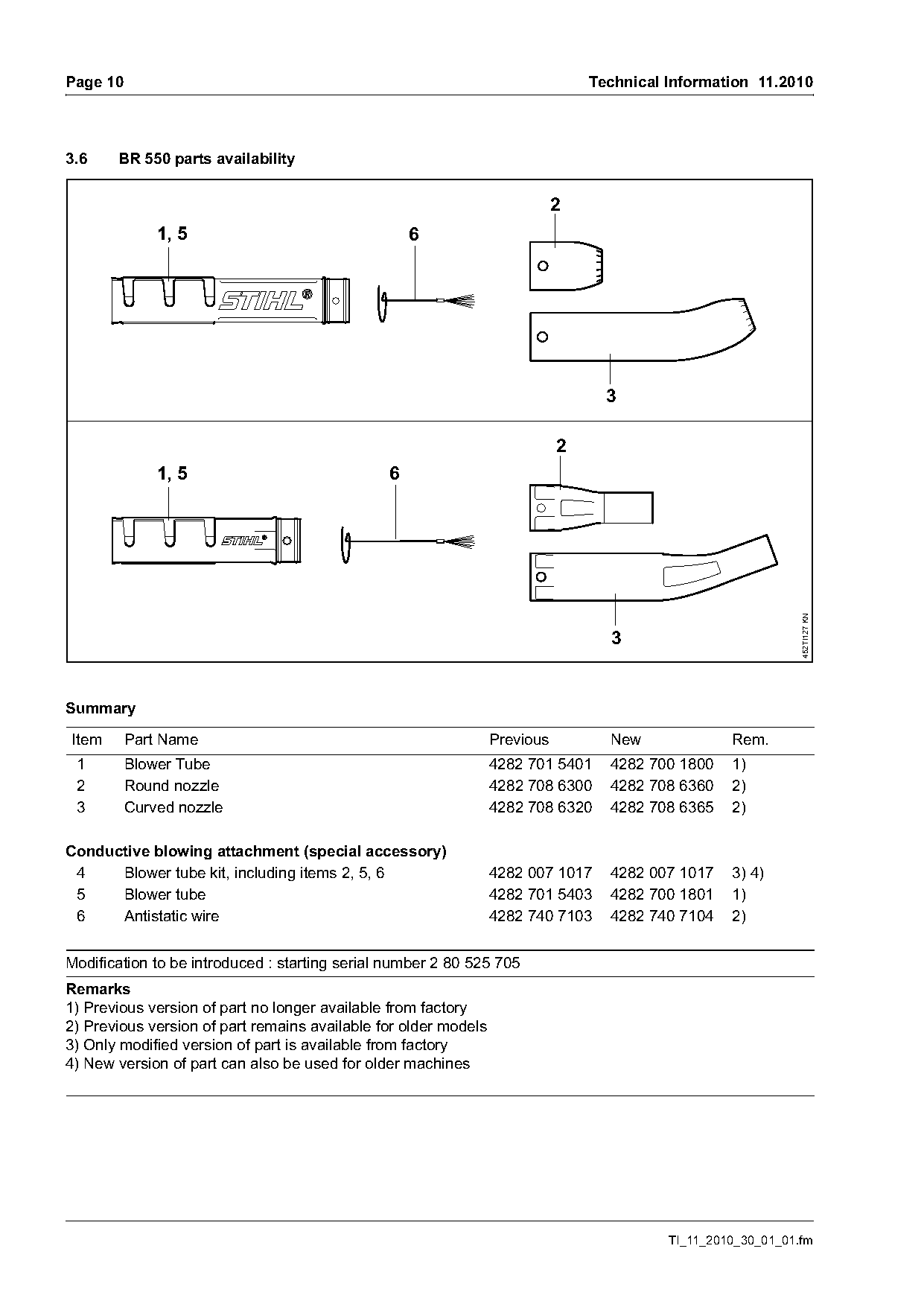
3.6    BR 550 parts availability

                                                                            2
              1, 5                                 6


                                                                            2
              1, 5                             6

                                                                                                              452TI127 KN
                                                                                  3

Summary

Item      Part Name                                              Previous         New              Rem.
 1        Blower Tube                                            4282 701 5401    4282 700 1800    1)
 2        Round nozzle                                           4282 708 6300    4282 708 6360    2)
 3        Curved nozzle                                          4282 708 6320    4282 708 6365    2)

Conductive blowing attachment (special accessory)
 4    Blower tube kit, including items 2, 5, 6                   4282 007 1017    4282 007 1017    3) 4)
 5    Blower tube                                                4282 701 5403    4282 700 1801    1)
 6    Antistatic wire                                            4282 740 7103    4282 740 7104    2)

Modification to be introduced : starting serial number 2 80 525 705
Remarks
1) Previous version of part no longer available from factory
2) Previous version of part remains available for older models
3) Only modified version of part is available from factory
4) New version of part can also be used for older machines

                                                                                          TI_11_2010_30_01_01.fm
Page 11 of 12
Text of page 11 — search, copy, screen readers
Technical Information 11.2010                                                                         Page 11

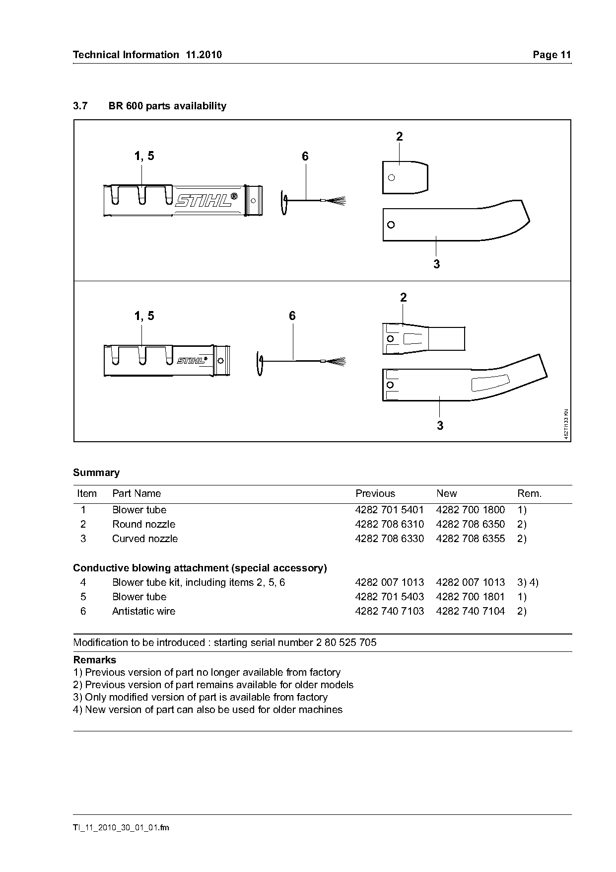
3.7     BR 600 parts availability

                                                                            2
             1, 5                                  6


                                                                            2
             1, 5                              6

                                                                                                           452TI133 KN
                                                                                 3

Summary

Item    Part Name                                                Previous        New             Rem.
 1      Blower tube                                              4282 701 5401   4282 700 1800   1)
 2      Round nozzle                                             4282 708 6310   4282 708 6350   2)
 3      Curved nozzle                                            4282 708 6330   4282 708 6355   2)

Conductive blowing attachment (special accessory)
 4    Blower tube kit, including items 2, 5, 6                   4282 007 1013   4282 007 1013   3) 4)
 5    Blower tube                                                4282 701 5403   4282 700 1801   1)
 6    Antistatic wire                                            4282 740 7103   4282 740 7104   2)

Modification to be introduced : starting serial number 2 80 525 705
Remarks
1) Previous version of part no longer available from factory
2) Previous version of part remains available for older models
3) Only modified version of part is available from factory
4) New version of part can also be used for older machines

TI_11_2010_30_01_01.fm
Page 12 of 12
Text of page 12 — search, copy, screen readers
Page 12                                                                              Technical Information 11.2010

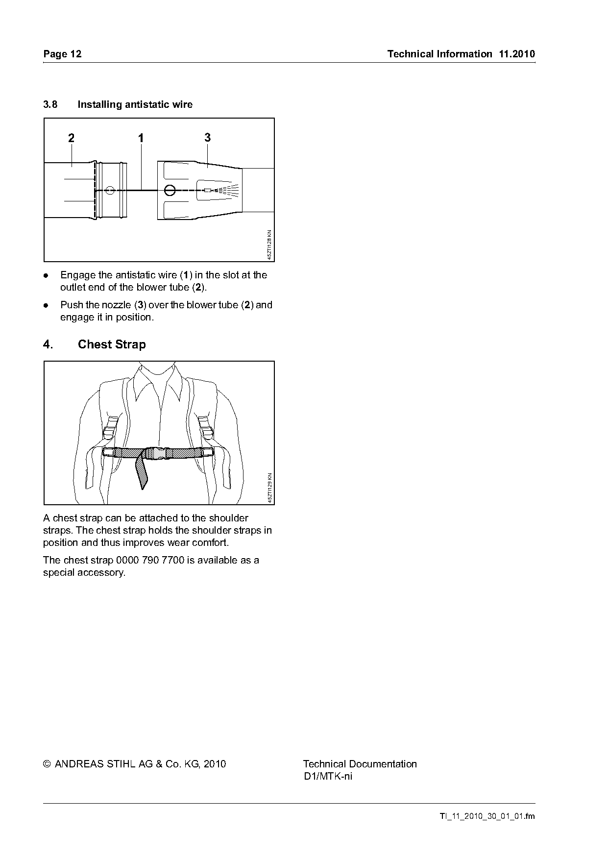
3.8        Installing antistatic wire

       2                1               3

                                                      452TI128 KN
.     Engage the antistatic wire (1) in the slot at the
      outlet end of the blower tube (2).
.     Push the nozzle (3) over the blower tube (2) and
      engage it in position.

4.         Chest Strap
                                                      452TI129 KN

A chest strap can be attached to the shoulder
straps. The chest strap holds the shoulder straps in
position and thus improves wear comfort.
The chest strap 0000 790 7700 is available as a
special accessory.

© ANDREAS STIHL AG & Co. KG, 2010                                   Technical Documentation
                                                                    D1/MTK-ni

                                                                                               TI_11_2010_30_01_01.fm
Most of these PDFs embed fonts with a shifted character map, so the text above was recovered rather than copied — read it as a faithful but imperfect transcription, and treat the page image above each block as the authority where the two disagree — the figures exist only there, because they are vector drawings that text extraction cannot keep.