Technical Information · issue 19 of 2010
New cut-off machines STIHL Cutquik® TS 410-A, TS 420-A
IssueTI 19/2010
Part changes (1)
| Was | Becomes | What the bulletin says |
|---|---|---|
| 0000 997 0912 | 0000 997 5510 | spring 0000 997 0912 with 6 coils is replaced by the new version 0000 997 5510 with 7 coils. |
Full text
Page 1 of 11
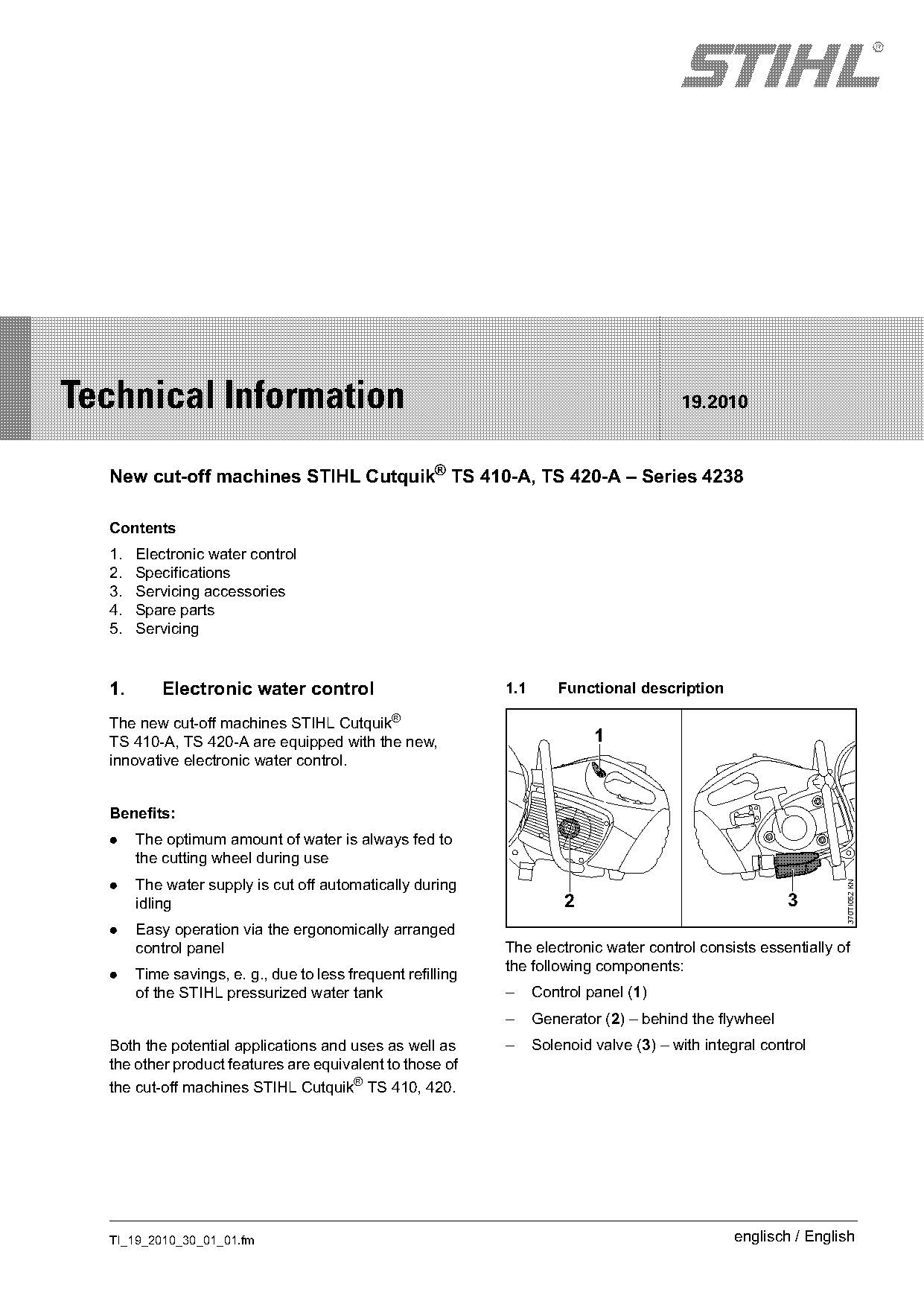
Text of page 1 — search, copy, screen readers
STIH)

Technical Information                                                                    19.2010

  New cut-off machines STIHL Cutquik® TS 410-A, TS 420-A – Series 4238

  Contents
  1.   Electronic water control
  2.   Specifications
  3.   Servicing accessories
  4.   Spare parts
  5.   Servicing

  1.       Electronic water control                          1.1       Functional description

  The new cut-off machines STIHL Cutquik®
  TS 410-A, TS 420-A are equipped with the new,                             1
  innovative electronic water control.

  Benefits:
  .    The optimum amount of water is always fed to
       the cutting wheel during use
  .    The water supply is cut off automatically during
                                                                                                                 370TI052 KN

       idling                                                           2                                 3
  .    Easy operation via the ergonomically arranged
       control panel                                         The electronic water control consists essentially of
                                                             the following components:
  .    Time savings, e. g., due to less frequent refilling
       of the STIHL pressurized water tank                   –     Control panel (1)
                                                             –     Generator (2) – behind the flywheel
  Both the potential applications and uses as well as        –     Solenoid valve (3) – with integral control
  the other product features are equivalent to those of
  the cut-off machines STIHL Cutquik® TS 410, 420.

  TI_19_2010_30_01_01.fm                                                                         englisch / English
Page 2 of 11
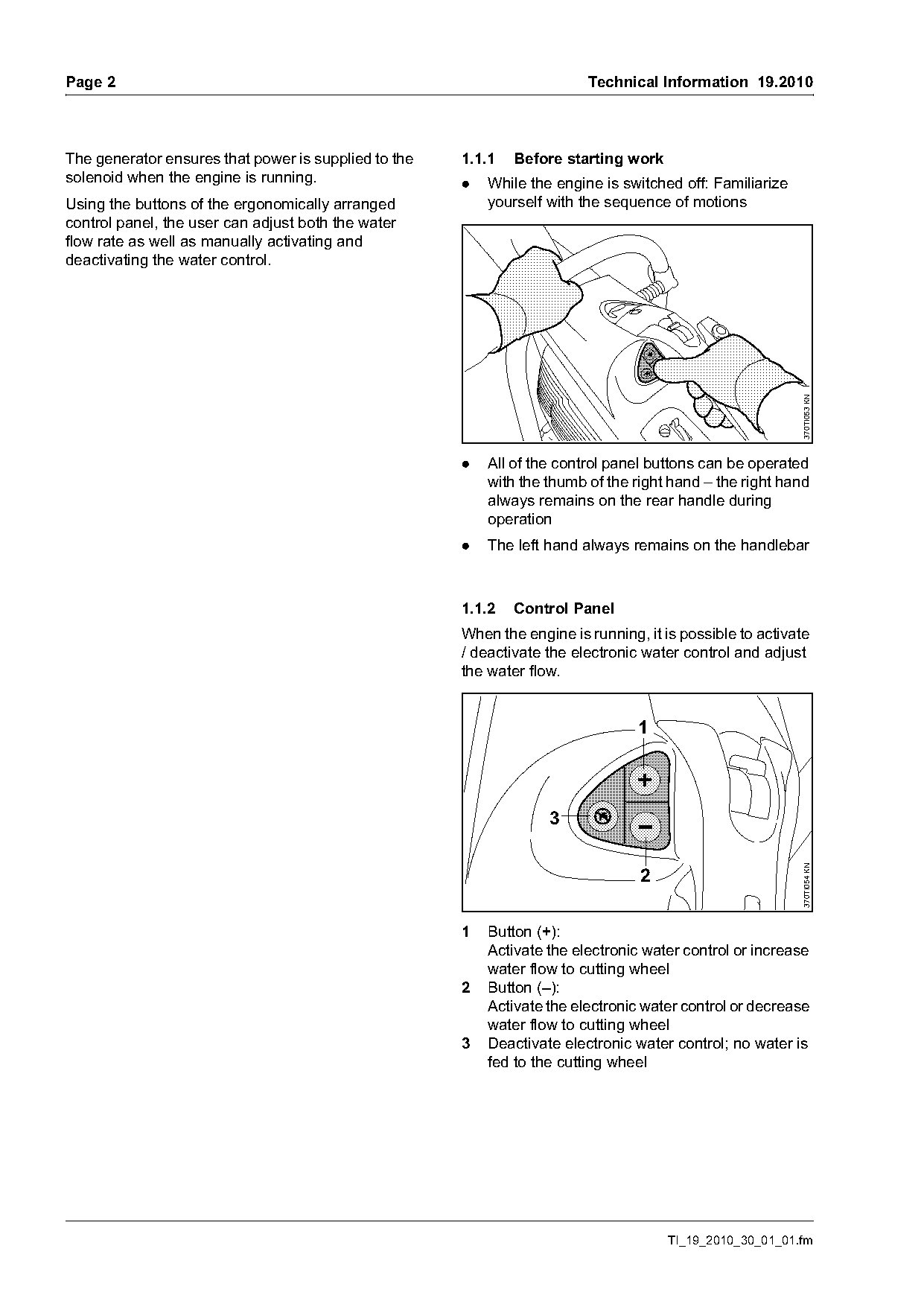
Text of page 2 — search, copy, screen readers
Page 2                                                                   Technical Information 19.2010

The generator ensures that power is supplied to the   1.1.1   Before starting work
solenoid when the engine is running.                  .   While the engine is switched off: Familiarize
Using the buttons of the ergonomically arranged           yourself with the sequence of motions
control panel, the user can adjust both the water
flow rate as well as manually activating and
deactivating the water control.

                                                                                                          370TI053 KN
                                                      .   All of the control panel buttons can be operated
                                                          with the thumb of the right hand – the right hand
                                                          always remains on the rear handle during
                                                          operation
                                                      .   The left hand always remains on the handlebar

                                                      1.1.2   Control Panel
                                                      When the engine is running, it is possible to activate
                                                      / deactivate the electronic water control and adjust
                                                      the water flow.


                                                                   3
                                                                                                          370TI054 KN


                                                      1   Button (+):
                                                          Activate the electronic water control or increase
                                                          water flow to cutting wheel
                                                      2   Button (–):
                                                          Activate the electronic water control or decrease
                                                          water flow to cutting wheel
                                                      3   Deactivate electronic water control; no water is
                                                          fed to the cutting wheel

                                                                                     TI_19_2010_30_01_01.fm
Page 3 of 11
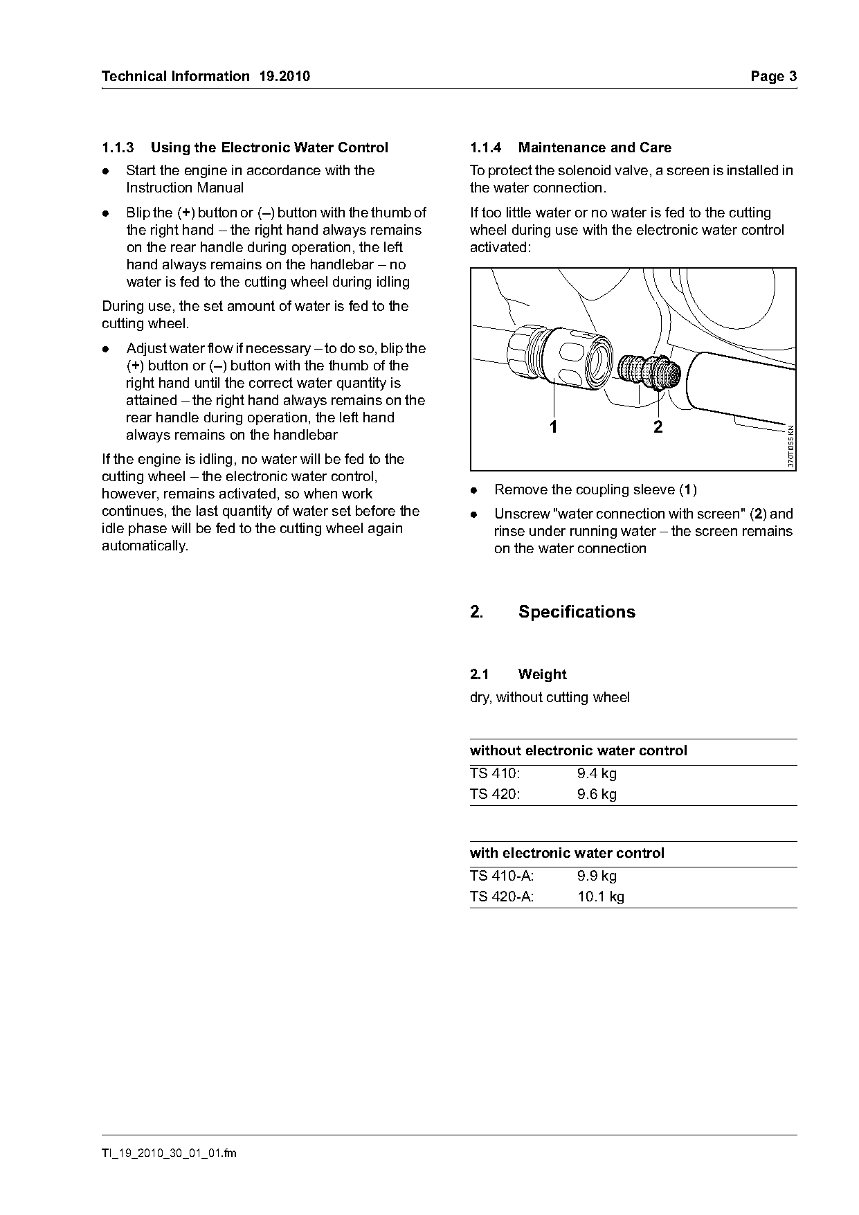
Text of page 3 — search, copy, screen readers
Technical Information 19.2010                                                                            Page 3

1.1.3   Using the Electronic Water Control                1.1.4    Maintenance and Care
.   Start the engine in accordance with the               To protect the solenoid valve, a screen is installed in
    Instruction Manual                                    the water connection.
.   Blip the (+) button or (–) button with the thumb of   If too little water or no water is fed to the cutting
    the right hand – the right hand always remains        wheel during use with the electronic water control
    on the rear handle during operation, the left         activated:
    hand always remains on the handlebar – no
    water is fed to the cutting wheel during idling
During use, the set amount of water is fed to the
cutting wheel.
.   Adjust water flow if necessary – to do so, blip the
    (+) button or (–) button with the thumb of the
    right hand until the correct water quantity is
    attained – the right hand always remains on the
    rear handle during operation, the left hand
                                                                        1                2

                                                                                                                  370TI055 KN
    always remains on the handlebar
If the engine is idling, no water will be fed to the
cutting wheel – the electronic water control,
however, remains activated, so when work                  .     Remove the coupling sleeve (1)
continues, the last quantity of water set before the      .     Unscrew "water connection with screen" (2) and
idle phase will be fed to the cutting wheel again               rinse under running water – the screen remains
automatically.                                                  on the water connection

                                                          2.       Specifications

                                                          2.1      Weight
                                                          dry, without cutting wheel

                                                          without electronic water control
                                                          TS 410:           9.4 kg
                                                          TS 420:           9.6 kg

                                                          with electronic water control
                                                          TS 410-A:         9.9 kg
                                                          TS 420-A:         10.1 kg

TI_19_2010_30_01_01.fm
Page 4 of 11
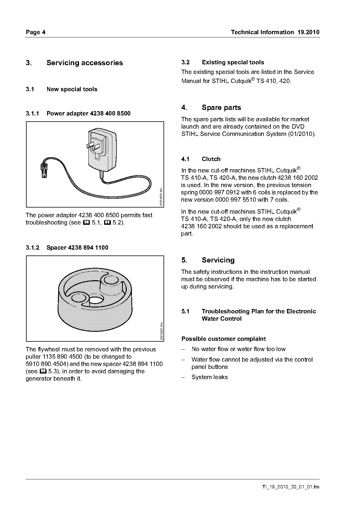
Text of page 4 — search, copy, screen readers
Page 4                                                                             Technical Information 19.2010

3.       Servicing accessories                                3.2      Existing special tools
                                                              The existing special tools are listed in the Service
                                                              Manual for STIHL Cutquik® TS 410, 420.
3.1      New special tools

                                                              4.       Spare parts
3.1.1    Power adapter 4238 400 8500
                                                              The spare parts lists will be available for market
                                                              launch and are already contained on the DVD
                                                              STIHL Service Communication System (01/2010).

                                                              4.1      Clutch
                                                              In the new cut-off machines STIHL Cutquik®
                                                              TS 410-A, TS 420-A, the new clutch 4238 160 2002
                                                              is used. In the new version, the previous tension
                                               370TI075 KN

                                                              spring 0000 997 0912 with 6 coils is replaced by the
                                                              new version 0000 997 5510 with 7 coils.
                                                              In the new cut-off machines STIHL Cutquik®
The power adapter 4238 400 8500 permits fast
                                                              TS 410-A, TS 420-A, only the new clutch
troubleshooting (see b 5.1, b 5.2).
                                                              4238 160 2002 should be used as a replacement
                                                              part.

3.1.2    Spacer 4238 894 1100

                                                              5.       Servicing
                                                              The safety instructions in the instruction manual
                                                              must be observed if the machine has to be started
                                                              up during servicing.

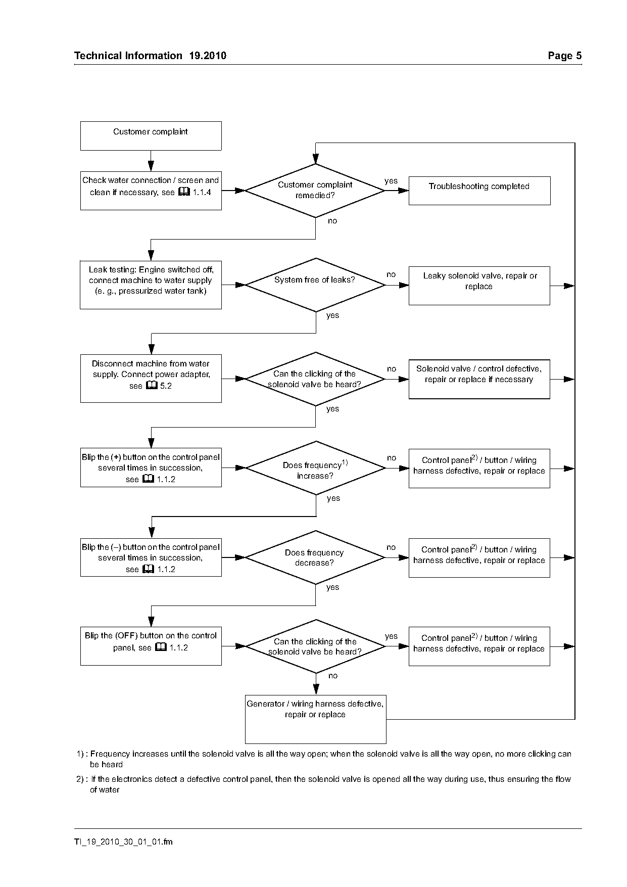
                                                              5.1      Troubleshooting Plan for the Electronic
                                                                       Water Control
                                                370TI057 KN

                                                              Possible customer complaint
The flywheel must be removed with the previous                –     No water flow or water flow too low
puller 1135 890 4500 (to be changed to                        –     Water flow cannot be adjusted via the control
5910 890 4504) and the new spacer 4238 894 1100                     panel buttons
(see b 5.3), in order to avoid damaging the
generator beneath it.                                         –     System leaks

                                                                                              TI_19_2010_30_01_01.fm
Page 5 of 11
Text of page 5 — search, copy, screen readers
Technical Information 19.2010                                                                                                        Page 5

          Customer complaint

 Check water connection / screen and                                                   yes
                                                        Customer complaint                        Troubleshooting completed
  clean if necessary, see b 1.1.4                           remedied?

   Leak testing: Engine switched off,
                                                                                       no       Leaky solenoid valve, repair or
   connect machine to water supply                     System free of leaks?
                                                                                                          replace
    (e. g., pressurized water tank)

                                                                     yes

    Disconnect machine from water
                                                                                       no     Solenoid valve / control defective,
    supply. Connect power adapter,                    Can the clicking of the
                                                                                                repair or replace if necessary
             see b 5.2                               solenoid valve be heard?

                                                                     yes

 Blip the (+) button on the control panel                                              no       Control panel2) / button / wiring
      several times in succession,                       Does frequency1)
                                                                                              harness defective, repair or replace
               see b 1.1.2                                  increase?

                                                                     yes

 Blip the (–) button on the control panel                                              no       Control panel2) / button / wiring
                                                          Does frequency
      several times in succession,                                                            harness defective, repair or replace
                                                            decrease?
               see b 1.1.2

                                                                     yes

  Blip the (OFF) button on the control                                                 yes      Control panel2) / button / wiring
                                                      Can the clicking of the
          panel, see b 1.1.2                                                                  harness defective, repair or replace
                                                     solenoid valve be heard?

                                               Generator / wiring harness defective,
                                                        repair or replace

1) : Frequency increases until the solenoid valve is all the way open; when the solenoid valve is all the way open, no more clicking can
     be heard
2) : If the electronics detect a defective control panel, then the solenoid valve is opened all the way during use, thus ensuring the flow
     of water

TI_19_2010_30_01_01.fm
Page 6 of 11
Text of page 6 — search, copy, screen readers
Page 6                                                                                Technical Information 19.2010

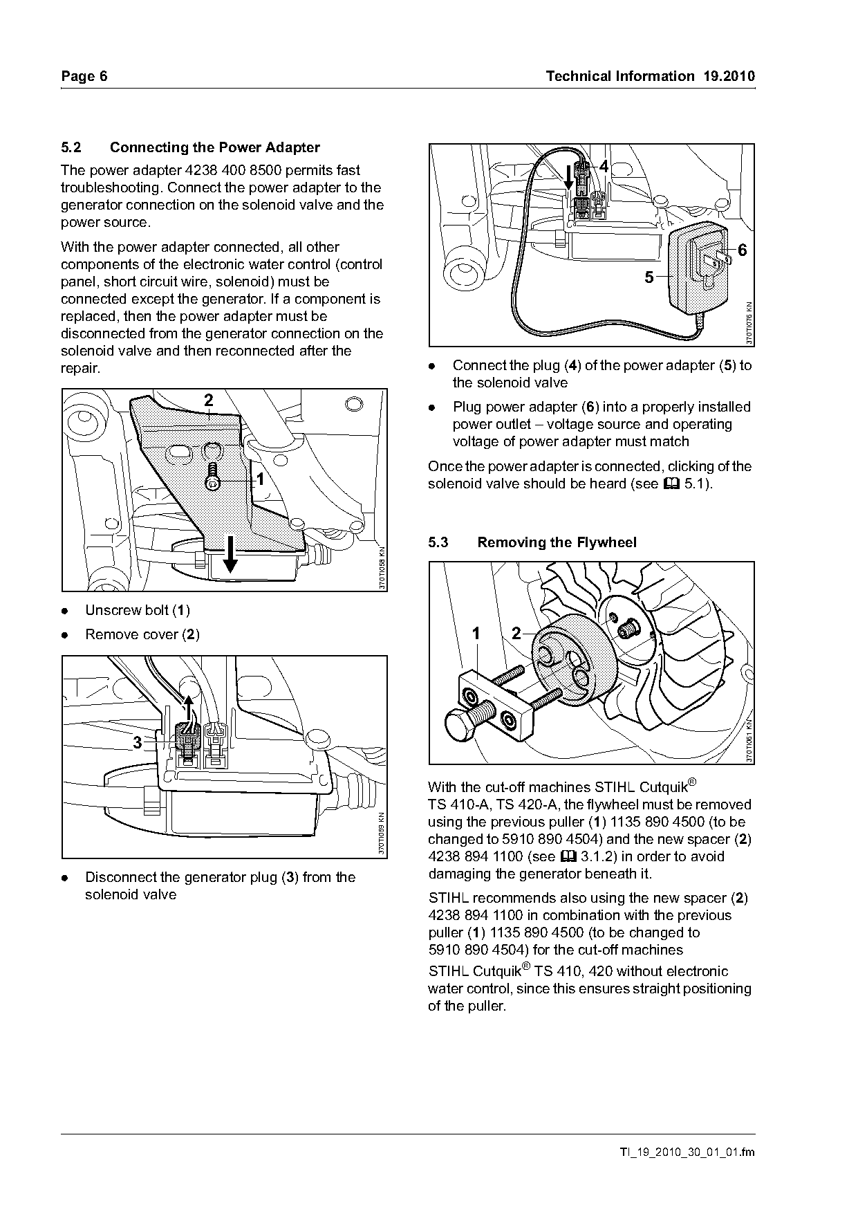
5.2      Connecting the Power Adapter
The power adapter 4238 400 8500 permits fast                                                  4
troubleshooting. Connect the power adapter to the
generator connection on the solenoid valve and the
power source.
With the power adapter connected, all other                                                                          6
components of the electronic water control (control
panel, short circuit wire, solenoid) must be                                                          5
connected except the generator. If a component is

                                                                                                                      370TI076 KN
replaced, then the power adapter must be
disconnected from the generator connection on the
solenoid valve and then reconnected after the
repair.                                                          .     Connect the plug (4) of the power adapter (5) to
                                                                       the solenoid valve
                         2                                       .     Plug power adapter (6) into a properly installed
                                                                       power outlet – voltage source and operating
                                                                       voltage of power adapter must match
                                                                 Once the power adapter is connected, clicking of the
                                1                                solenoid valve should be heard (see b 5.1).

                                                                 5.3      Removing the Flywheel
                                                   370TI058 KN

.     Unscrew bolt (1)
.     Remove cover (2)                                                    1     2

                                                                                                                      370TI061 KN
             3

                                                                 With the cut-off machines STIHL Cutquik®
                                                                 TS 410-A, TS 420-A, the flywheel must be removed
                                                   370TI059 KN

                                                                 using the previous puller (1) 1135 890 4500 (to be
                                                                 changed to 5910 890 4504) and the new spacer (2)
                                                                 4238 894 1100 (see b 3.1.2) in order to avoid
.     Disconnect the generator plug (3) from the                 damaging the generator beneath it.
      solenoid valve                                             STIHL recommends also using the new spacer (2)
                                                                 4238 894 1100 in combination with the previous
                                                                 puller (1) 1135 890 4500 (to be changed to
                                                                 5910 890 4504) for the cut-off machines
                                                                 STIHL Cutquik® TS 410, 420 without electronic
                                                                 water control, since this ensures straight positioning
                                                                 of the puller.

                                                                                                  TI_19_2010_30_01_01.fm
Page 7 of 11
Text of page 7 — search, copy, screen readers
Technical Information 19.2010                                                                                     Page 7

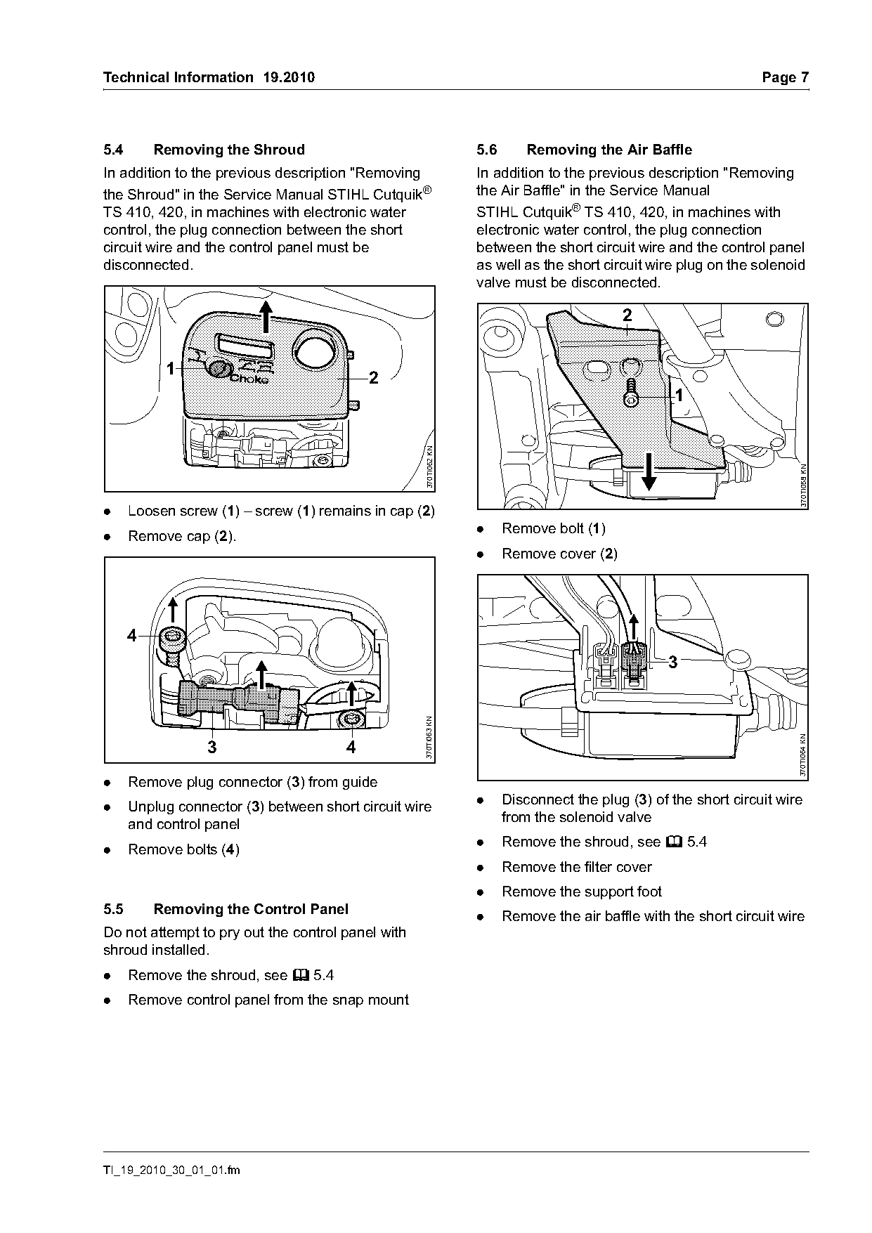
5.4       Removing the Shroud                                     5.6       Removing the Air Baffle
In addition to the previous description "Removing                 In addition to the previous description "Removing
the Shroud" in the Service Manual STIHL Cutquik®                  the Air Baffle" in the Service Manual
TS 410, 420, in machines with electronic water                    STIHL Cutquik® TS 410, 420, in machines with
control, the plug connection between the short                    electronic water control, the plug connection
circuit wire and the control panel must be                        between the short circuit wire and the control panel
disconnected.                                                     as well as the short circuit wire plug on the solenoid
                                                                  valve must be disconnected.


           1
                                           2
                                                                                                    1
                                                    370TI062 KN

                                                                                                                        370TI058 KN
.     Loosen screw (1) – screw (1) remains in cap (2)
                                                                  .     Remove bolt (1)
.     Remove cap (2).
                                                                  .     Remove cover (2)

      4
                                                                                                   3
                                                   370TI063 KN

                                                                                                                        370TI064 KN
                  3                    4
.     Remove plug connector (3) from guide
                                                                  .     Disconnect the plug (3) of the short circuit wire
.     Unplug connector (3) between short circuit wire
                                                                        from the solenoid valve
      and control panel
                                                                  .     Remove the shroud, see b 5.4
.     Remove bolts (4)
                                                                  .     Remove the filter cover
                                                                  .     Remove the support foot
5.5       Removing the Control Panel
                                                                  .     Remove the air baffle with the short circuit wire
Do not attempt to pry out the control panel with
shroud installed.
.     Remove the shroud, see b 5.4
.     Remove control panel from the snap mount

TI_19_2010_30_01_01.fm
Page 8 of 11
Text of page 8 — search, copy, screen readers
Page 8                                                                                  Technical Information 19.2010

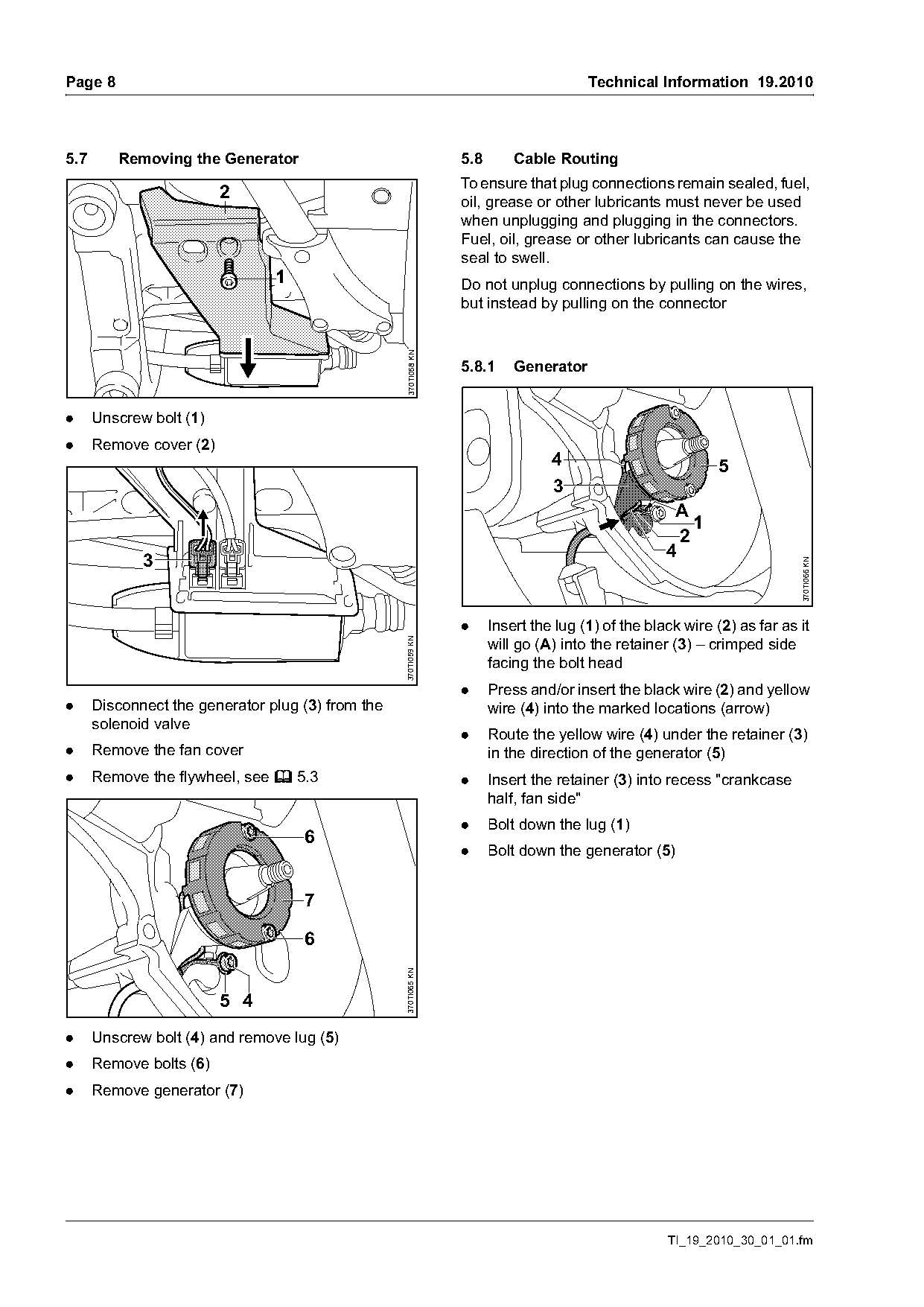
5.7      Removing the Generator                                   5.8       Cable Routing
                                                                  To ensure that plug connections remain sealed, fuel,
                         2                                        oil, grease or other lubricants must never be used
                                                                  when unplugging and plugging in the connectors.
                                                                  Fuel, oil, grease or other lubricants can cause the
                                                                  seal to swell.
                                1                                 Do not unplug connections by pulling on the wires,
                                                                  but instead by pulling on the connector

                                                    370TI058 KN
                                                                  5.8.1     Generator

.     Unscrew bolt (1)
.     Remove cover (2)
                                                                                  4                           5
                                                                                  3
                                                                                                      A
                                                                                                         1
                                                                                                       2
                                                                                                     4
             3

                                                                                                                           370TI066 KN
                                                                  .     Insert the lug (1) of the black wire (2) as far as it
                                                                        will go (A) into the retainer (3) – crimped side
                                                   370TI059 KN

                                                                        facing the bolt head
                                                                  .     Press and/or insert the black wire (2) and yellow
.     Disconnect the generator plug (3) from the                        wire (4) into the marked locations (arrow)
      solenoid valve
                                                                  .     Route the yellow wire (4) under the retainer (3)
.     Remove the fan cover                                              in the direction of the generator (5)
.     Remove the flywheel, see b 5.3                              .     Insert the retainer (3) into recess "crankcase
                                                                        half, fan side"
                                                                  .     Bolt down the lug (1)
                                    6
                                                                  .     Bolt down the generator (5)


                                    6
                                                   370TI065 KN

                         5 4
.     Unscrew bolt (4) and remove lug (5)
.     Remove bolts (6)
.     Remove generator (7)

                                                                                                     TI_19_2010_30_01_01.fm
Page 9 of 11
Text of page 9 — search, copy, screen readers
Technical Information 19.2010                                                                                       Page 9

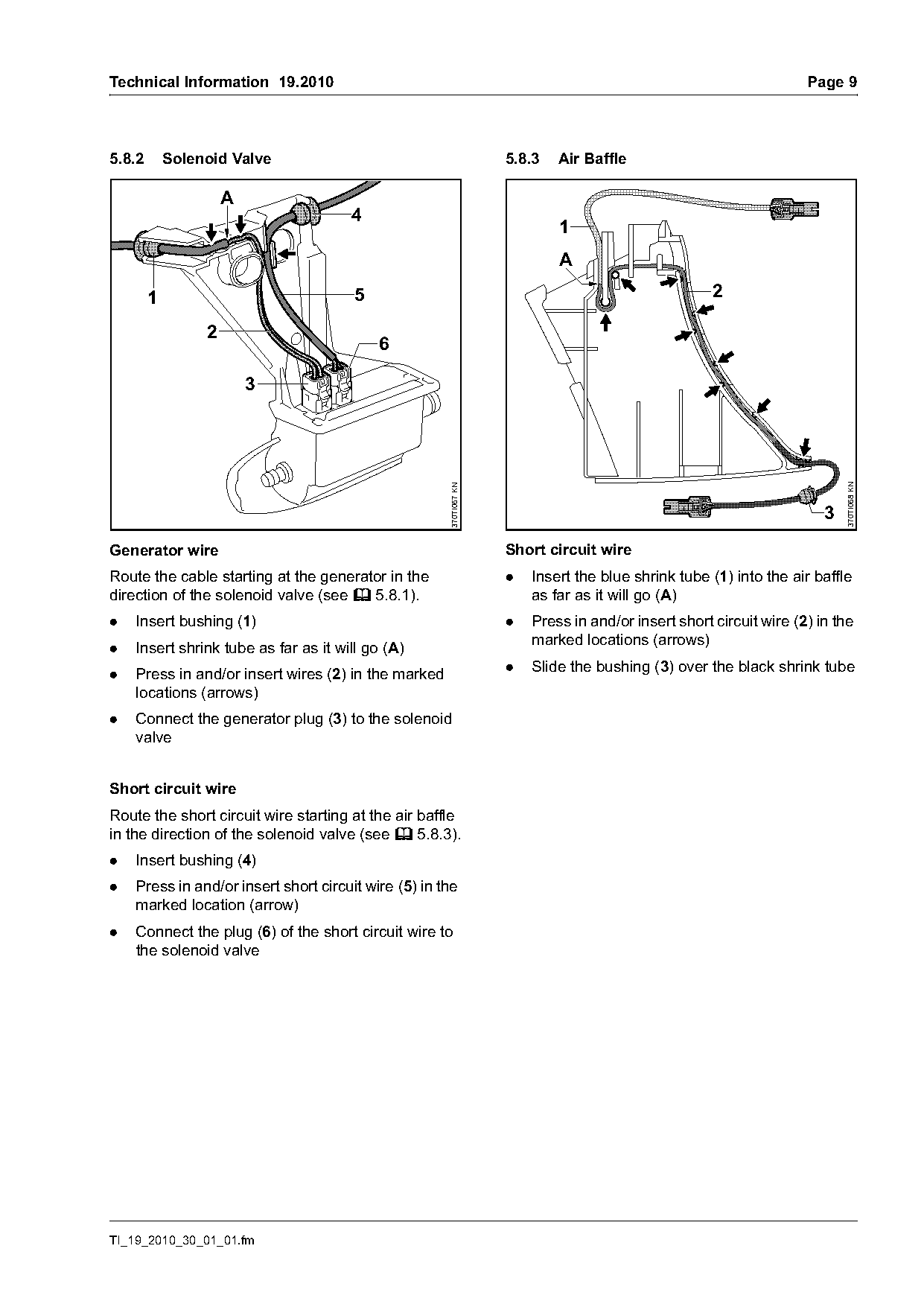
5.8.2       Solenoid Valve                                          5.8.3   Air Baffle

                     A
                                      4
                                                                            1
                                                                            A

        1                              5                                                             2

                 2
                                           6


                                                                                                                           370TI068 KN
                                                      370TI067 KN

                                                                                                                       3
Generator wire                                                      Short circuit wire
Route the cable starting at the generator in the                    .   Insert the blue shrink tube (1) into the air baffle
direction of the solenoid valve (see b 5.8.1).                          as far as it will go (A)
.   Insert bushing (1)                                              .   Press in and/or insert short circuit wire (2) in the
                                                                        marked locations (arrows)
.   Insert shrink tube as far as it will go (A)
.   Press in and/or insert wires (2) in the marked                  .   Slide the bushing (3) over the black shrink tube
    locations (arrows)
.   Connect the generator plug (3) to the solenoid
    valve

Short circuit wire
Route the short circuit wire starting at the air baffle
in the direction of the solenoid valve (see b 5.8.3).
.   Insert bushing (4)
.   Press in and/or insert short circuit wire (5) in the
    marked location (arrow)
.   Connect the plug (6) of the short circuit wire to
    the solenoid valve

TI_19_2010_30_01_01.fm
Page 10 of 11
Text of page 10 — search, copy, screen readers
Page 10                                                                               Technical Information 19.2010

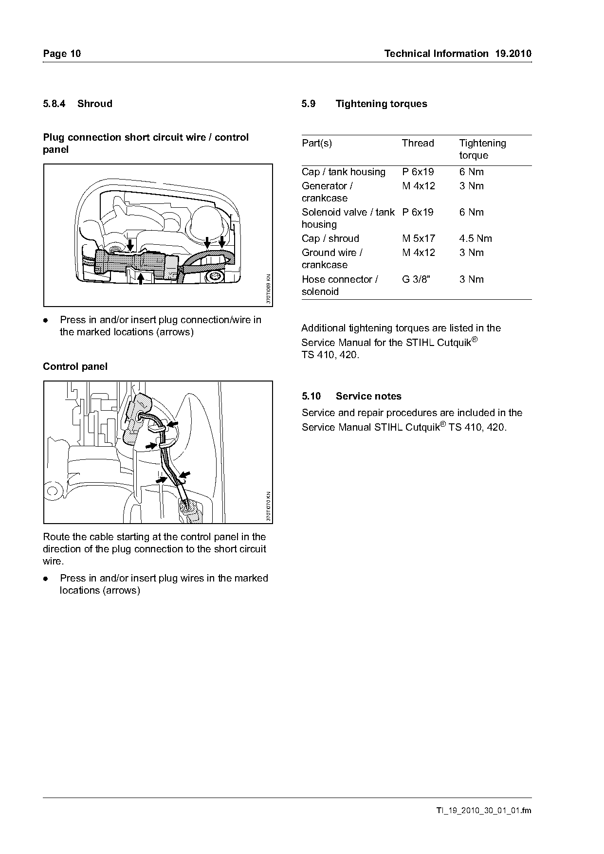
5.8.4   Shroud                                                     5.9       Tightening torques

Plug connection short circuit wire / control
                                                                   Part(s)                   Thread        Tightening
panel
                                                                                                           torque
                                                                   Cap / tank housing        P 6x19        6 Nm
                                                                   Generator /               M 4x12        3 Nm
                                                                   crankcase
                                                                   Solenoid valve / tank     P 6x19        6 Nm
                                                                   housing
                                                                   Cap / shroud              M 5x17        4.5 Nm
                                                                   Ground wire /             M 4x12        3 Nm
                                                                   crankcase
                                                                   Hose connector /          G 3/8"        3 Nm
                                                     370TI069 KN

                                                                   solenoid

.   Press in and/or insert plug connection/wire in
    the marked locations (arrows)                                  Additional tightening torques are listed in the
                                                                   Service Manual for the STIHL Cutquik®
                                                                   TS 410, 420.
Control panel

                                                                   5.10      Service notes
                                                                   Service and repair procedures are included in the
                                                                   Service Manual STIHL Cutquik® TS 410, 420.
                                                     370TI070 KN

Route the cable starting at the control panel in the
direction of the plug connection to the short circuit
wire.
.   Press in and/or insert plug wires in the marked
    locations (arrows)

                                                                                                      TI_19_2010_30_01_01.fm
Page 11 of 11
Text of page 11 — search, copy, screen readers
Technical Information 19.2010                                                                                                       Page 11

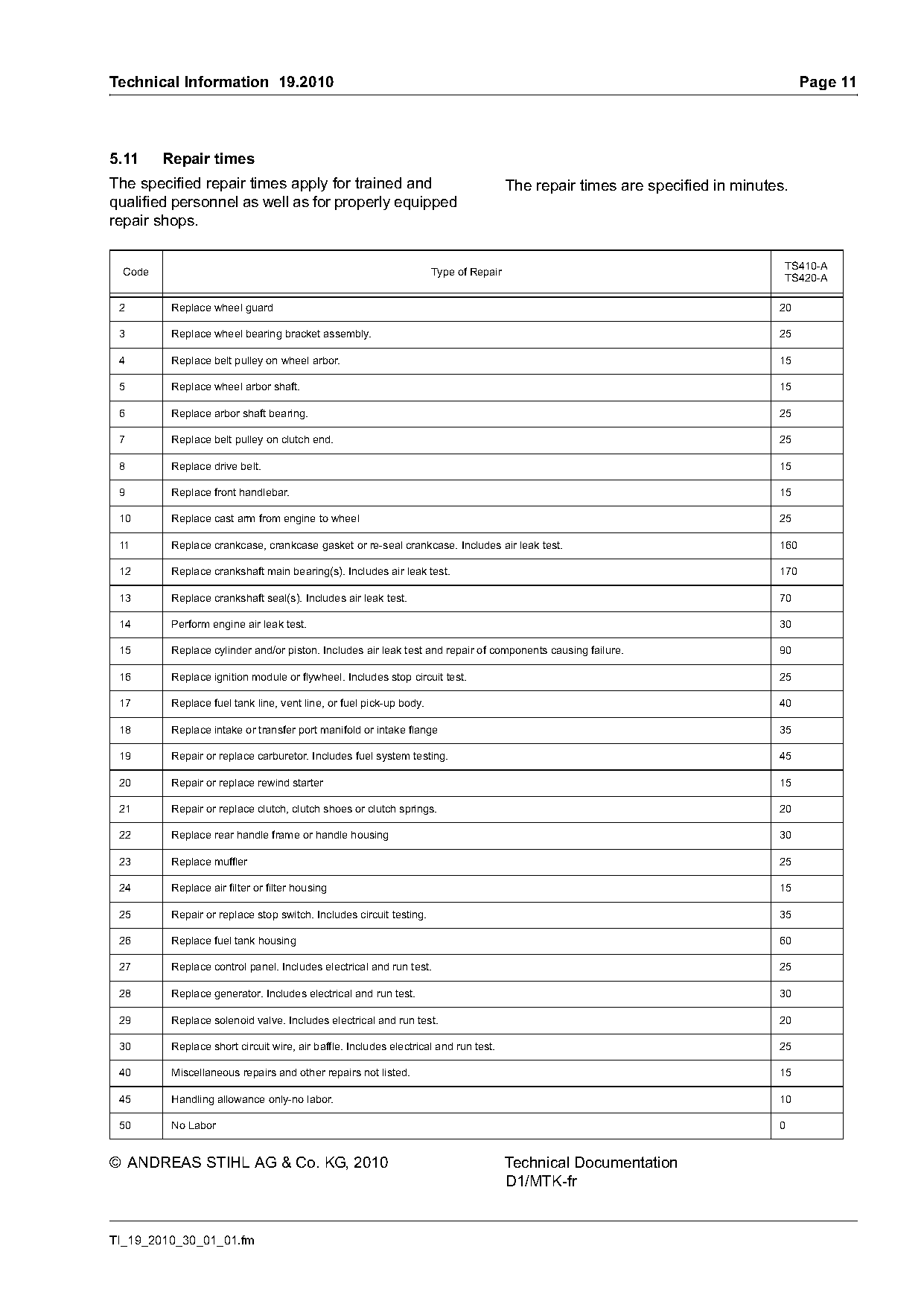
5.11     Repair times
The specified repair times apply for trained and                                      The repair times are specified in minutes.
qualified personnel as well as for properly equipped
repair shops.

                                                                                                                               TS410-A
  Code                                                               Type of Repair
                                                                                                                               TS420-A

 2        Replace wheel guard                                                                                                 20

 3        Replace wheel bearing bracket assembly.                                                                             25

 4        Replace belt pulley on wheel arbor.                                                                                 15

 5        Replace wheel arbor shaft.                                                                                          15

 6        Replace arbor shaft bearing.                                                                                        25

 7        Replace belt pulley on clutch end.                                                                                  25

 8        Replace drive belt.                                                                                                 15

 9        Replace front handlebar.                                                                                            15

 10       Replace cast arm from engine to wheel                                                                               25

 11       Replace crankcase, crankcase gasket or re-seal crankcase. Includes air leak test.                                   160

 12       Replace crankshaft main bearing(s). Includes air leak test.                                                         170

 13       Replace crankshaft seal(s). Includes air leak test.                                                                 70

 14       Perform engine air leak test.                                                                                       30

 15       Replace cylinder and/or piston. Includes air leak test and repair of components causing failure.                    90

 16       Replace ignition module or flywheel. Includes stop circuit test.                                                    25

 17       Replace fuel tank line, vent line, or fuel pick-up body.                                                            40

 18       Replace intake or transfer port manifold or intake flange                                                           35

 19       Repair or replace carburetor. Includes fuel system testing.                                                         45

 20       Repair or replace rewind starter                                                                                    15

 21       Repair or replace clutch, clutch shoes or clutch springs.                                                           20

 22       Replace rear handle frame or handle housing                                                                         30

 23       Replace muffler                                                                                                     25

 24       Replace air filter or filter housing                                                                                15

 25       Repair or replace stop switch. Includes circuit testing.                                                            35

 26       Replace fuel tank housing                                                                                           60

 27       Replace control panel. Includes electrical and run test.                                                            25

 28       Replace generator. Includes electrical and run test.                                                                30

 29       Replace solenoid valve. Includes electrical and run test.                                                           20

 30       Replace short circuit wire, air baffle. Includes electrical and run test.                                           25

 40       Miscellaneous repairs and other repairs not listed.                                                                 15

 45       Handling allowance only-no labor.                                                                                   10

 50       No Labor                                                                                                            0

© ANDREAS STIHL AG & Co. KG, 2010                                                     Technical Documentation
                                                                                      D1/MTK-fr

TI_19_2010_30_01_01.fm
Most of these PDFs embed fonts with a shifted character map, so the text above was recovered rather than copied — read it as a faithful but imperfect transcription, and treat the page image above each block as the authority where the two disagree — the figures exist only there, because they are vector drawings that text extraction cannot keep.