Technical Information · issue 25 of 2010
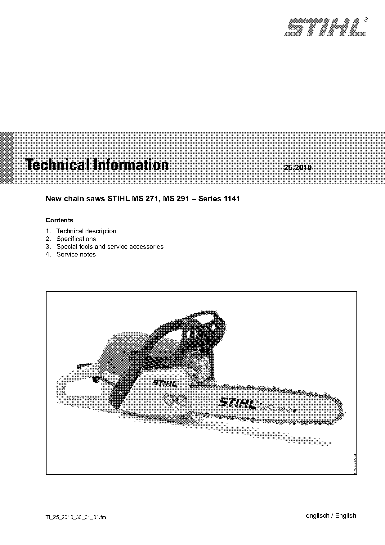
New chain saws STIHL MS 271, MS 291
IssueTI 25/2010
Engine family 1141
Part changes (2)
| Was | Becomes | What the bulletin says |
|---|---|---|
| 5910 855 4201 | 5910 890 4504 | Item Designation Part number Use 1 Press sleeve 1141 893 2401 Press in oil seal 2 Flange 5910 855 4201 Engine leakage test Puller 5910 890 4504 The previous puller 1135 890 4500 is being replaced by the new version 5910 890 4504. |
| 4224 893 2501 | 5910 855 4201 | Rework information The previous flange 4224 893 2501 is being replaced by the new version 5910 855 4201. |
Full text
Page 1 of 15
Text of page 1 — search, copy, screen readers
STIH)

Technical Information                                 25.2010

  New chain saws STIHL MS 271, MS 291 – Series 1141

  Contents
  1.   Technical description
  2.   Specifications
  3.   Special tools and service accessories
  4.   Service notes

  TI_25_2010_30_01_01.fm                                   englisch / English
Page 2 of 15
Text of page 2 — search, copy, screen readers
Page 2                                                                     Technical Information 25.2010

The new 1141 series STIHL MS 271 and STIHL              1.      Technical description
MS 291 chain saws with an innovative engine
concept and filter system are especially powerful,      1.1     Reduced emissions engine
economical, clean and low-maintenance. These
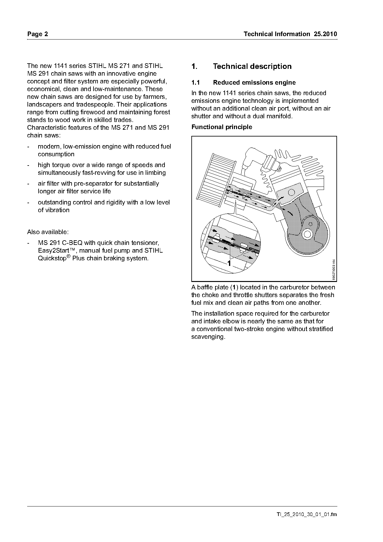
                                                        In the new 1141 series chain saws, the reduced
new chain saws are designed for use by farmers,
                                                        emissions engine technology is implemented
landscapers and tradespeople. Their applications
                                                        without an additional clean air port, without an air
range from cutting firewood and maintaining forest
                                                        shutter and without a dual manifold.
stands to wood work in skilled trades.
Characteristic features of the MS 271 and MS 291        Functional principle
chain saws:
-   modern, low-emission engine with reduced fuel
    consumption
-   high torque over a wide range of speeds and
    simultaneously fast-revving for use in limbing
-   air filter with pre-separator for substantially
    longer air filter service life
-   outstanding control and rigidity with a low level
    of vibration

Also available:
-   MS 291 C-BEQ with quick chain tensioner,
    Easy2Start™, manual fuel pump and STIHL
    Quickstop® Plus chain braking system.
                                                                     1

                                                                                                               5902TI003 KN
                                                        A baffle plate (1) located in the carburetor between
                                                        the choke and throttle shutters separates the fresh
                                                        fuel mix and clean air paths from one another.
                                                        The installation space required for the carburetor
                                                        and intake elbow is nearly the same as that for
                                                        a conventional two-stroke engine without stratified
                                                        scavenging.

                                                                                       TI_25_2010_30_01_01.fm
Page 3 of 15
Text of page 3 — search, copy, screen readers
Technical Information 25.2010                                                                                         Page 3

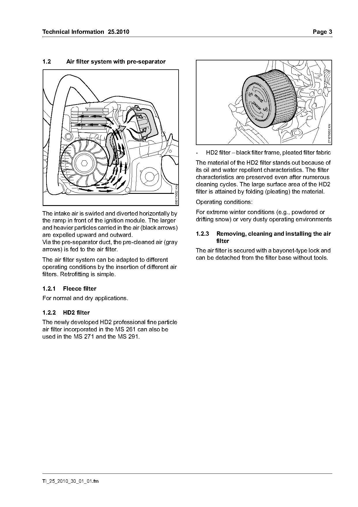
1.2      Air filter system with pre-separator

                                                                                                                            2710TI002 KN
                                                                    -   HD2 filter – black filter frame, pleated filter fabric
                                                                    The material of the HD2 filter stands out because of
                                                                    its oil and water repellent characteristics. The filter
                                                                    characteristics are preserved even after numerous
                                                                    cleaning cycles. The large surface area of the HD2
                                                     0001TI002 KN

                                                                    filter is attained by folding (pleating) the material.
                                                                    Operating conditions:
The intake air is swirled and diverted horizontally by              For extreme winter conditions (e.g., powdered or
the ramp in front of the ignition module. The larger                drifting snow) or very dusty operating environments
and heavier particles carried in the air (black arrows)
are expelled upward and outward.                                    1.2.3   Removing, cleaning and installing the air
Via the pre-separator duct, the pre-cleaned air (gray                       filter
arrows) is fed to the air filter.                                   The air filter is secured with a bayonet-type lock and
The air filter system can be adapted to different                   can be detached from the filter base without tools.
operating conditions by the insertion of different air
filters. Retrofitting is simple.

1.2.1   Fleece filter
For normal and dry applications.

1.2.2   HD2 filter
The newly developed HD2 professional fine particle
air filter incorporated in the MS 261 can also be
used in the MS 271 and the MS 291.

TI_25_2010_30_01_01.fm
Page 4 of 15
Text of page 4 — search, copy, screen readers
Page 4                                                                                     Technical Information 25.2010

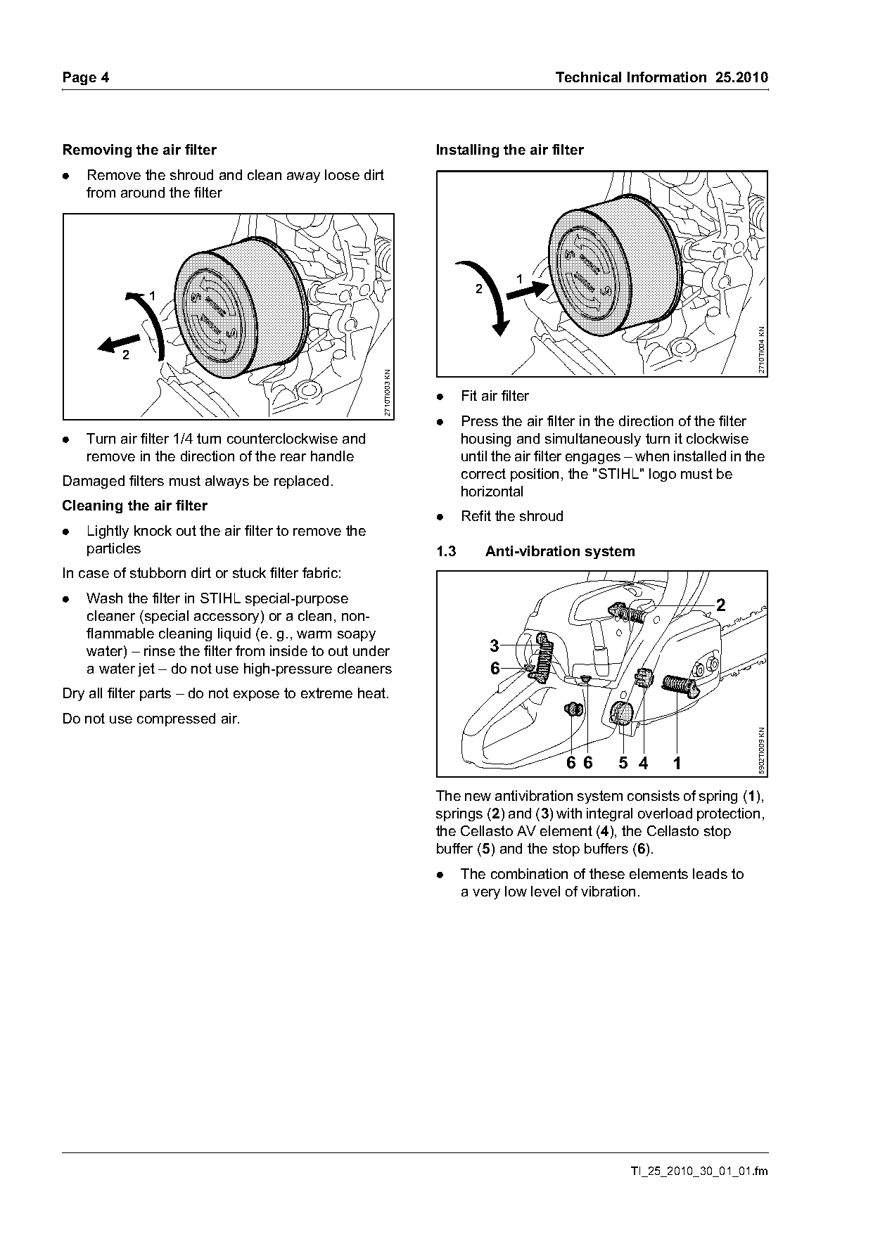
Removing the air filter                                             Installing the air filter
.   Remove the shroud and clean away loose dirt
    from around the filter

                                                                                     1
                                                                             2
              1

                                                                                                                            2710TI004 KN
          2

                                                     2710TI003 KN
                                                                    .     Fit air filter
                                                                    .     Press the air filter in the direction of the filter
.   Turn air filter 1/4 turn counterclockwise and                         housing and simultaneously turn it clockwise
    remove in the direction of the rear handle                            until the air filter engages – when installed in the
                                                                          correct position, the "STIHL" logo must be
Damaged filters must always be replaced.
                                                                          horizontal
Cleaning the air filter
                                                                    .     Refit the shroud
.   Lightly knock out the air filter to remove the
    particles                                                       1.3          Anti-vibration system
In case of stubborn dirt or stuck filter fabric:
.   Wash the filter in STIHL special-purpose
                                                                                                                     2
    cleaner (special accessory) or a clean, non-
    flammable cleaning liquid (e. g., warm soapy
    water) – rinse the filter from inside to out under                           3
    a water jet – do not use high-pressure cleaners                              6
Dry all filter parts – do not expose to extreme heat.
Do not use compressed air.

                                                                                                                            5902TI009 KN
                                                                                             6 6    5 4       1
                                                                    The new antivibration system consists of spring (1),
                                                                    springs (2) and (3) with integral overload protection,
                                                                    the Cellasto AV element (4), the Cellasto stop
                                                                    buffer (5) and the stop buffers (6).
                                                                    .     The combination of these elements leads to
                                                                          a very low level of vibration.

                                                                                                       TI_25_2010_30_01_01.fm
Page 5 of 15
Text of page 5 — search, copy, screen readers
Technical Information 25.2010                                                                                    Page 5

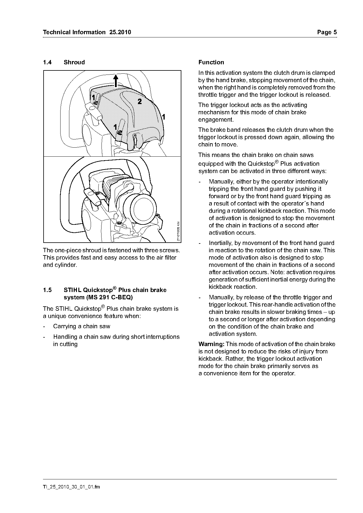
1.4      Shroud                                                   Function
                                                                  In this activation system the clutch drum is clamped
                                                                  by the hand brake, stopping movement of the chain,
                                                                  when the right hand is completely removed from the
                                                                  throttle trigger and the trigger lockout is released.
                                                                  The trigger lockout acts as the activating
                                                                  mechanism for this mode of chain brake
                                                                  engagement.
                                                                  The brake band releases the clutch drum when the
                                                                  trigger lockout is pressed down again, allowing the
                                                                  chain to move.
                                                                  This means the chain brake on chain saws
                                                                  equipped with the Quickstop® Plus activation
                                                                  system can be activated in three different ways:
                                                                  -   Manually, either by the operator intentionally
                                                                      tripping the front hand guard by pushing it
                                                                      forward or by the front hand guard tripping as
                                                                      a result of contact with the operator´s hand
                                                                      during a rotational kickback reaction. This mode
                                                                      of activation is designed to stop the movement
                                                   2710TI005 KN

                                                                      of the chain in fractions of a second after
                                                                      activation occurs.
                                                                  -   Inertially, by movement of the front hand guard
The one-piece shroud is fastened with three screws.                   in reaction to the rotation of the chain saw. This
This provides fast and easy access to the air filter                  mode of activation also is designed to stop
and cylinder.                                                         movement of the chain in fractions of a second
                                                                      after activation occurs. Note: activation requires
                                                                      generation of sufficient inertial energy during the
                                                                      kickback reaction.
1.5      STIHL Quickstop® Plus chain brake
         system (MS 291 C-BEQ)                                    -   Manually, by release of the throttle trigger and
                                                                      trigger lockout. This rear-handle activation of the
The STIHL Quickstop® Plus chain brake system is
                                                                      chain brake results in slower braking times – up
a unique convenience feature when:
                                                                      to a second or longer after activation depending
-     Carrying a chain saw                                            on the condition of the chain brake and
-     Handling a chain saw during short interruptions                 activation system.
      in cutting                                                  Warning: This mode of activation of the chain brake
                                                                  is not designed to reduce the risks of injury from
                                                                  kickback. Rather, the trigger lockout activation
                                                                  mode for the chain brake primarily serves as
                                                                  a convenience item for the operator.

TI_25_2010_30_01_01.fm
Page 6 of 15
Text of page 6 — search, copy, screen readers
Page 6                                                                      Technical Information 25.2010

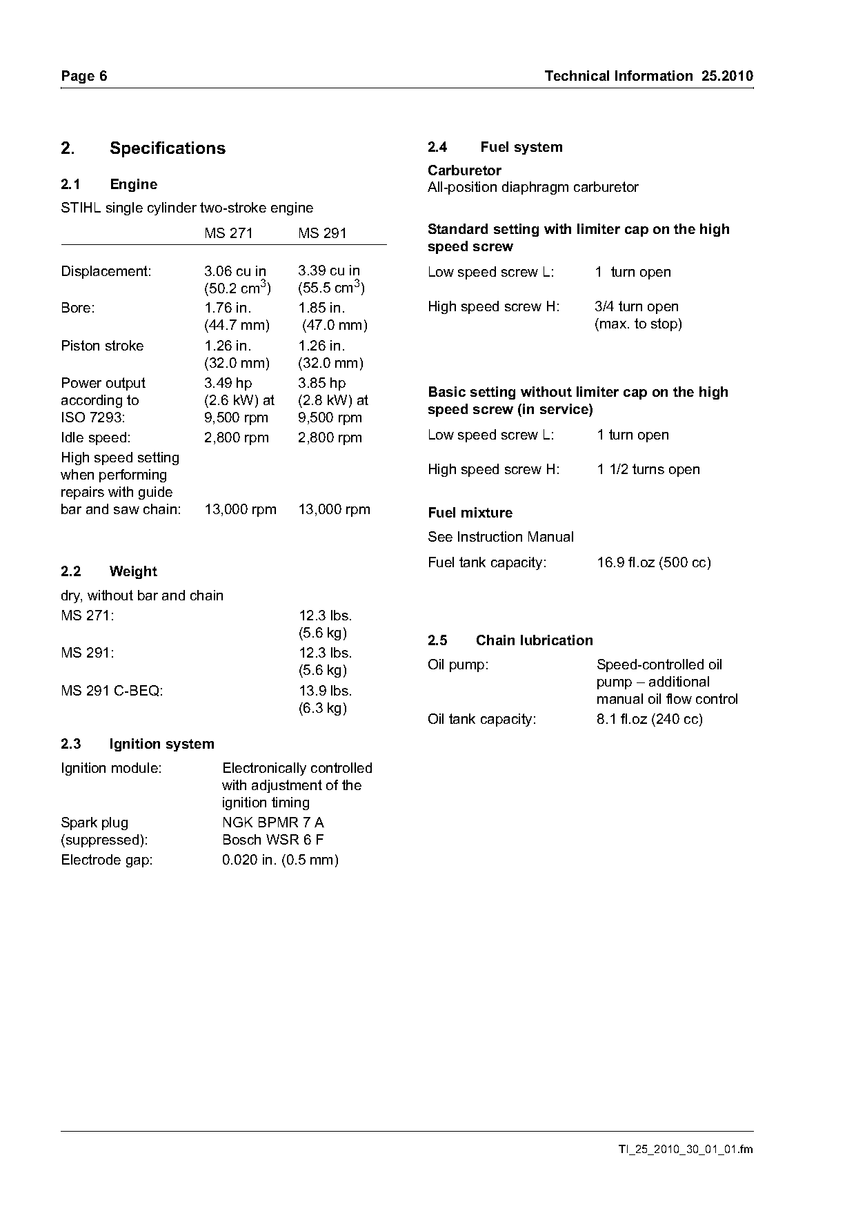
2.       Specifications                                2.4     Fuel system
                                                       Carburetor
2.1      Engine                                        All-position diaphragm carburetor
STIHL single cylinder two-stroke engine
                      MS 271           MS 291          Standard setting with limiter cap on the high
                                                       speed screw
Displacement:         3.06 cu in       3.39 cu in      Low speed screw L:          1 turn open
                      (50.2 cm3)       (55.5 cm3)
Bore:                 1.76 in.         1.85 in.        High speed screw H:         3/4 turn open
                      (44.7 mm)         (47.0 mm)                                  (max. to stop)
Piston stroke         1.26 in.         1.26 in.
                      (32.0 mm)        (32.0 mm)
Power output          3.49 hp          3.85 hp
                                                       Basic setting without limiter cap on the high
according to          (2.6 kW) at      (2.8 kW) at
                                                       speed screw (in service)
ISO 7293:             9,500 rpm        9,500 rpm
Idle speed:           2,800 rpm        2,800 rpm       Low speed screw L:          1 turn open
High speed setting
when performing                                        High speed screw H:         1 1/2 turns open
repairs with guide
bar and saw chain:    13,000 rpm       13,000 rpm      Fuel mixture
                                                       See Instruction Manual
                                                       Fuel tank capacity:         16.9 fl.oz (500 cc)
2.2      Weight
dry, without bar and chain
MS 271:                                12.3 lbs.
                                       (5.6 kg)        2.5     Chain lubrication
MS 291:                                12.3 lbs.
                                       (5.6 kg)        Oil pump:                   Speed-controlled oil
                                                                                   pump – additional
MS 291 C-BEQ:                          13.9 lbs.
                                                                                   manual oil flow control
                                       (6.3 kg)
                                                       Oil tank capacity:          8.1 fl.oz (240 cc)
2.3      Ignition system
Ignition module:           Electronically controlled
                           with adjustment of the
                           ignition timing
Spark plug                 NGK BPMR 7 A
(suppressed):              Bosch WSR 6 F
Electrode gap:             0.020 in. (0.5 mm)

                                                                                      TI_25_2010_30_01_01.fm
Page 7 of 15
Text of page 7 — search, copy, screen readers
Technical Information 25.2010             Page 7

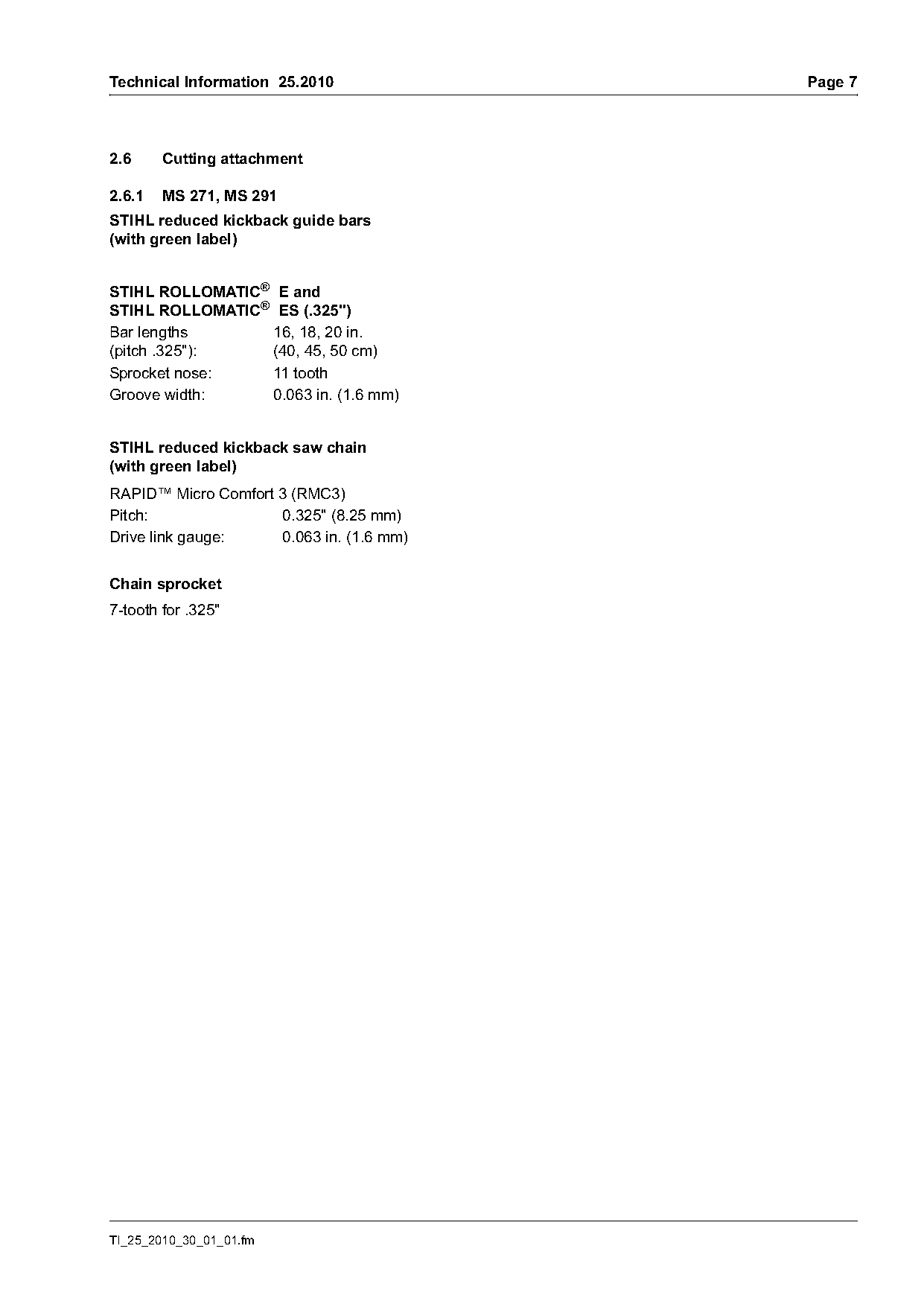
2.6     Cutting attachment

2.6.1   MS 271, MS 291
STIHL reduced kickback guide bars
(with green label)

STIHL ROLLOMATIC® E and
STIHL ROLLOMATIC® ES (.325")
Bar lengths      16, 18, 20 in.
(pitch .325"):   (40, 45, 50 cm)
Sprocket nose:   11 tooth
Groove width:    0.063 in. (1.6 mm)

STIHL reduced kickback saw chain
(with green label)
RAPID™ Micro Comfort 3 (RMC3)
Pitch:               0.325" (8.25 mm)
Drive link gauge:    0.063 in. (1.6 mm)

Chain sprocket
7-tooth for .325"

TI_25_2010_30_01_01.fm
Page 8 of 15
Text of page 8 — search, copy, screen readers
Page 8                                                                                   Technical Information 25.2010

3.         Special tools and service
           accessories

3.1        Special tools
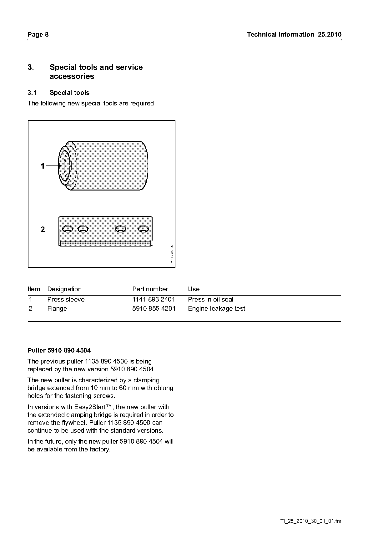
The following new special tools are required


       2
                                                    2710TI006 KN

Item       Designation                Part number                  Use
1          Press sleeve               1141 893 2401                Press in oil seal
2          Flange                     5910 855 4201                Engine leakage test

Puller 5910 890 4504
The previous puller 1135 890 4500 is being
replaced by the new version 5910 890 4504.
The new puller is characterized by a clamping
bridge extended from 10 mm to 60 mm with oblong
holes for the fastening screws.
In versions with Easy2Start™, the new puller with
the extended clamping bridge is required in order to
remove the flywheel. Puller 1135 890 4500 can
continue to be used with the standard versions.
In the future, only the new puller 5910 890 4504 will
be available from the factory.

                                                                                                   TI_25_2010_30_01_01.fm
Page 9 of 15
Text of page 9 — search, copy, screen readers
Technical Information 25.2010                                                                          Page 9

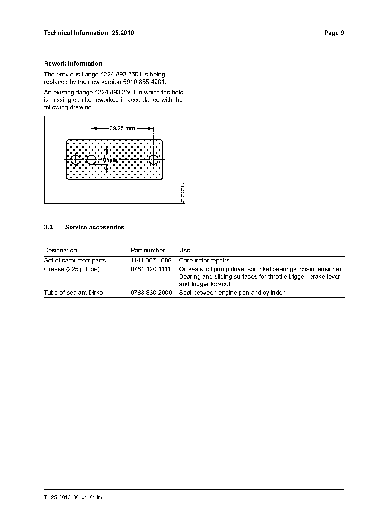
Rework information
The previous flange 4224 893 2501 is being
replaced by the new version 5910 855 4201.
An existing flange 4224 893 2501 in which the hole
is missing can be reworked in accordance with the
following drawing.

                          39,25 mm

                                                 2710TI007 KN

3.2     Service accessories

Designation                     Part number     Use
Set of carburetor parts         1141 007 1006   Carburetor repairs
Grease (225 g tube)             0781 120 1111   Oil seals, oil pump drive, sprocket bearings, chain tensioner
                                                Bearing and sliding surfaces for throttle trigger, brake lever
                                                and trigger lockout
Tube of sealant Dirko           0783 830 2000   Seal between engine pan and cylinder

TI_25_2010_30_01_01.fm
Page 10 of 15
Text of page 10 — search, copy, screen readers
Page 10                                                                                    Technical Information 25.2010

4.       Service notes
The specific national safety regulations and the                                                       1
safety instructions in the Instruction Manual must be
observed when starting and operating the chain
saw.
Only use the chain saw with the shroud mounted –
otherwise the rotating fan wheel poses a risk of
injury and there is a risk of engine damage due to
overheating.

                                                                                                                                 5902TI015 KN
4.1      Carburetor
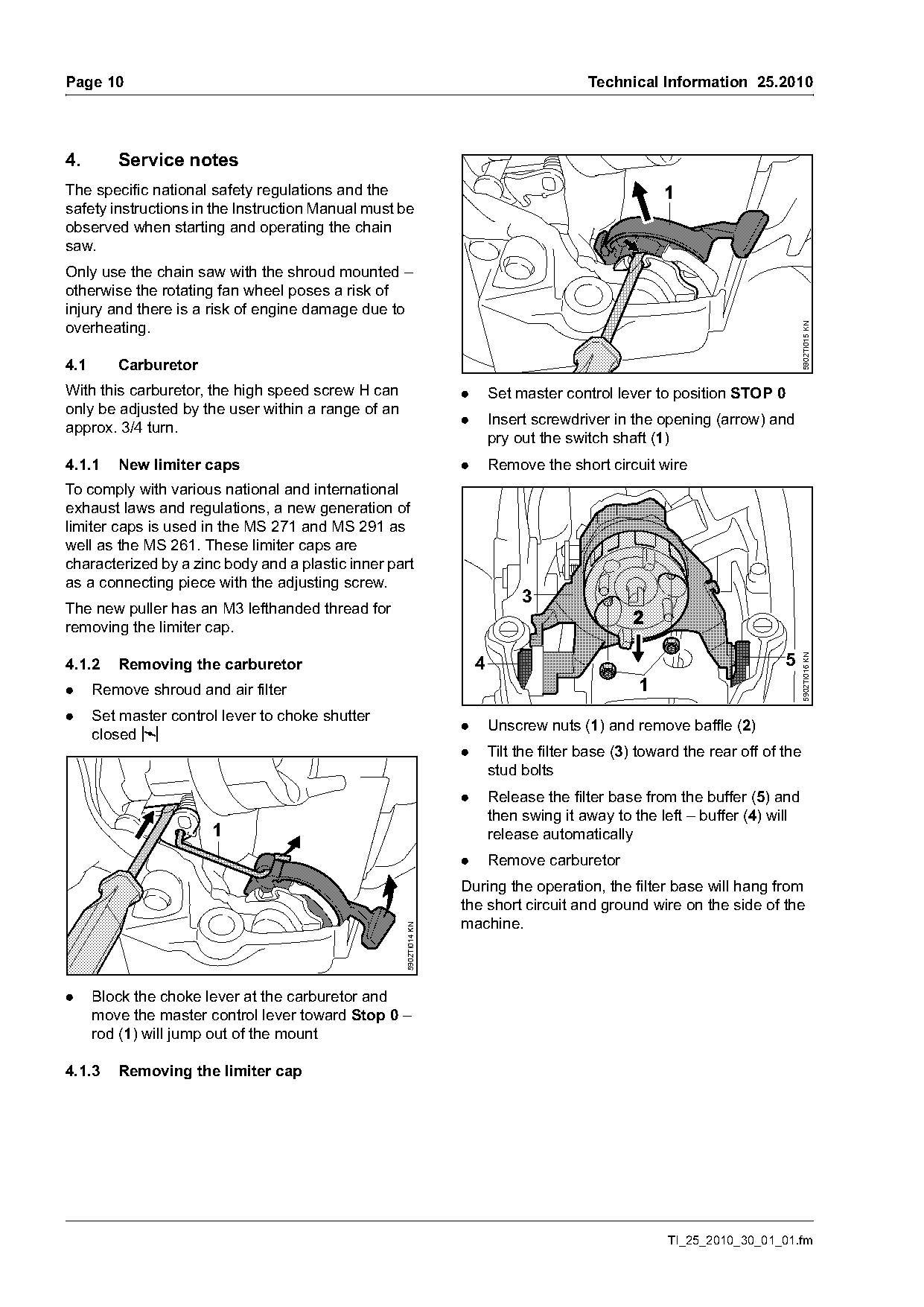
With this carburetor, the high speed screw H can                   .       Set master control lever to position STOP 0
only be adjusted by the user within a range of an
                                                                   .       Insert screwdriver in the opening (arrow) and
approx. 3/4 turn.
                                                                           pry out the switch shaft (1)
4.1.1    New limiter caps                                          .       Remove the short circuit wire
To comply with various national and international
exhaust laws and regulations, a new generation of
limiter caps is used in the MS 271 and MS 291 as
well as the MS 261. These limiter caps are
characterized by a zinc body and a plastic inner part
as a connecting piece with the adjusting screw.
                                                                                3
The new puller has an M3 lefthanded thread for
removing the limiter cap.


                                                                                                                                 5902TI016 KN
4.1.2    Removing the carburetor                                       4
.     Remove shroud and air filter                                                                 1
.     Set master control lever to choke shutter
                                                                   .       Unscrew nuts (1) and remove baffle (2)
      closed l
                                                                   .       Tilt the filter base (3) toward the rear off of the
                                                                           stud bolts
                                                                   .       Release the filter base from the buffer (5) and
                                                                           then swing it away to the left – buffer (4) will
                       1                                                   release automatically
                                                                   .       Remove carburetor
                                                                   During the operation, the filter base will hang from
                                                                   the short circuit and ground wire on the side of the
                                                                   machine.
                                                    5902TI014 KN

.     Block the choke lever at the carburetor and
      move the master control lever toward Stop 0 –
      rod (1) will jump out of the mount

4.1.3    Removing the limiter cap

                                                                                                        TI_25_2010_30_01_01.fm
Page 11 of 15
Text of page 11 — search, copy, screen readers
Technical Information 25.2010                                                                                    Page 11

                                                                  4.1.4   Basic setting
                                                                  After servicing or replacement of the adjusting
                         3                                        screws, it is necessary to perform a basic setting of
                                 2                                the carburetor.
                                           1
                                                                  .   Check the air filter – clean or replace it if
                                                                      necessary
                                                                  .   Check the spark arresting screen in the muffler
                                                                      – clean or replace it if necessary

                                                   5902TI017 KN
                                                                  The following screwdrivers should be used for the
                                                                  basic setting.
                                                                  -   Low speed screw L
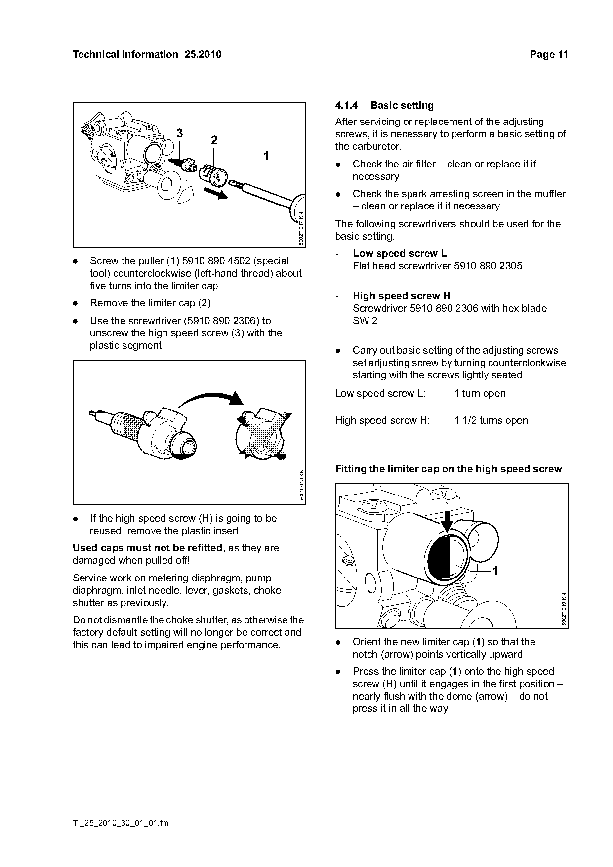
.   Screw the puller (1) 5910 890 4502 (special                       Flat head screwdriver 5910 890 2305
    tool) counterclockwise (left-hand thread) about
    five turns into the limiter cap
                                                                  -   High speed screw H
.   Remove the limiter cap (2)
                                                                      Screwdriver 5910 890 2306 with hex blade
.   Use the screwdriver (5910 890 2306) to                            SW 2
    unscrew the high speed screw (3) with the
    plastic segment                                               .   Carry out basic setting of the adjusting screws –
                                                                      set adjusting screw by turning counterclockwise
                                                                      starting with the screws lightly seated
                                                                  Low speed screw L:          1 turn open

                                                                  High speed screw H:         1 1/2 turns open

                                                                  Fitting the limiter cap on the high speed screw
                                                   5902TI018 KN

.   If the high speed screw (H) is going to be
    reused, remove the plastic insert
Used caps must not be refitted, as they are
damaged when pulled off!
                                                                                                        1
Service work on metering diaphragm, pump
diaphragm, inlet needle, lever, gaskets, choke
                                                                                                                       5902TI019 KN

shutter as previously.
Do not dismantle the choke shutter, as otherwise the
factory default setting will no longer be correct and
this can lead to impaired engine performance.                     .   Orient the new limiter cap (1) so that the
                                                                      notch (arrow) points vertically upward
                                                                  .   Press the limiter cap (1) onto the high speed
                                                                      screw (H) until it engages in the first position –
                                                                      nearly flush with the dome (arrow) – do not
                                                                      press it in all the way

TI_25_2010_30_01_01.fm
Page 12 of 15
Text of page 12 — search, copy, screen readers
Page 12                                                                                   Technical Information 25.2010

.    Install the carburetor                                         Once the maximum speed of 13,000 rpm is
                                                                    reached, do not continue to make the mix leaner –
                                                                    the ignition module limits the maximum speed to
                                                                    13,000 rpm. The permissible maximum speed
                                                                    cannot be increased by continuing to make the mix
                   1                                                leaner. Making the setting too lean increases the
                                                                    risk of engine damage.

                                                                    6.      Check the position of the limiter cap and
                                                                            secure the limiter cap on the high speed
                                                                            screw

                                                     5902TI022 KN   4.1.5    Checking the position of the limiter cap
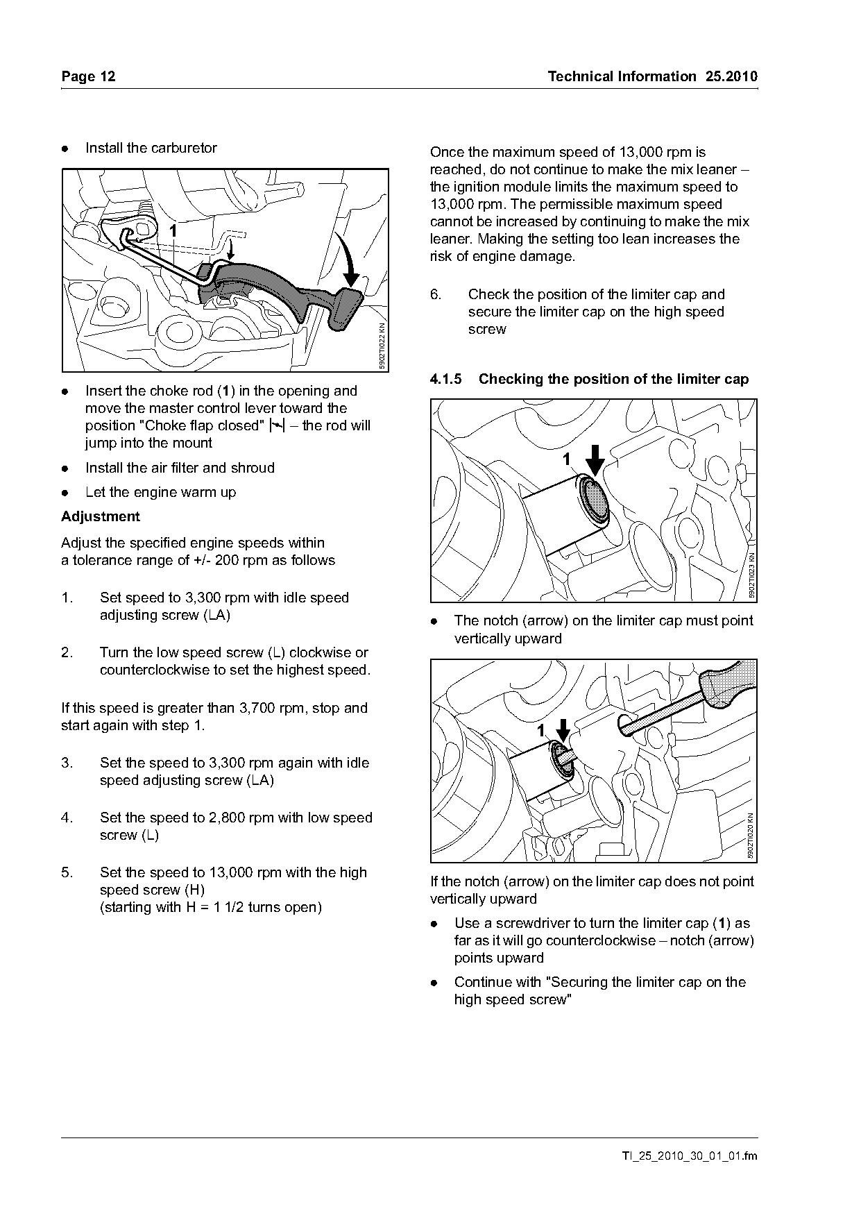
.    Insert the choke rod (1) in the opening and
     move the master control lever toward the
     position "Choke flap closed" l – the rod will
     jump into the mount
.    Install the air filter and shroud
                                                                                           1
.    Let the engine warm up
Adjustment
Adjust the specified engine speeds within
a tolerance range of +/- 200 rpm as follows

                                                                                                                           5902TI023 KN
1.     Set speed to 3,300 rpm with idle speed
       adjusting screw (LA)                                         .    The notch (arrow) on the limiter cap must point
                                                                         vertically upward
2.     Turn the low speed screw (L) clockwise or
       counterclockwise to set the highest speed.

If this speed is greater than 3,700 rpm, stop and
start again with step 1.                                                              1
3.     Set the speed to 3,300 rpm again with idle
       speed adjusting screw (LA)

4.     Set the speed to 2,800 rpm with low speed
                                                                                                                          5902TI020 KN

       screw (L)

5.     Set the speed to 13,000 rpm with the high
                                                                    If the notch (arrow) on the limiter cap does not point
       speed screw (H)
                                                                    vertically upward
       (starting with H = 1 1/2 turns open)
                                                                    .    Use a screwdriver to turn the limiter cap (1) as
                                                                         far as it will go counterclockwise – notch (arrow)
                                                                         points upward
                                                                    .    Continue with "Securing the limiter cap on the
                                                                         high speed screw"

                                                                                                    TI_25_2010_30_01_01.fm
Page 13 of 15
Text of page 13 — search, copy, screen readers
Technical Information 25.2010                                                                                    Page 13

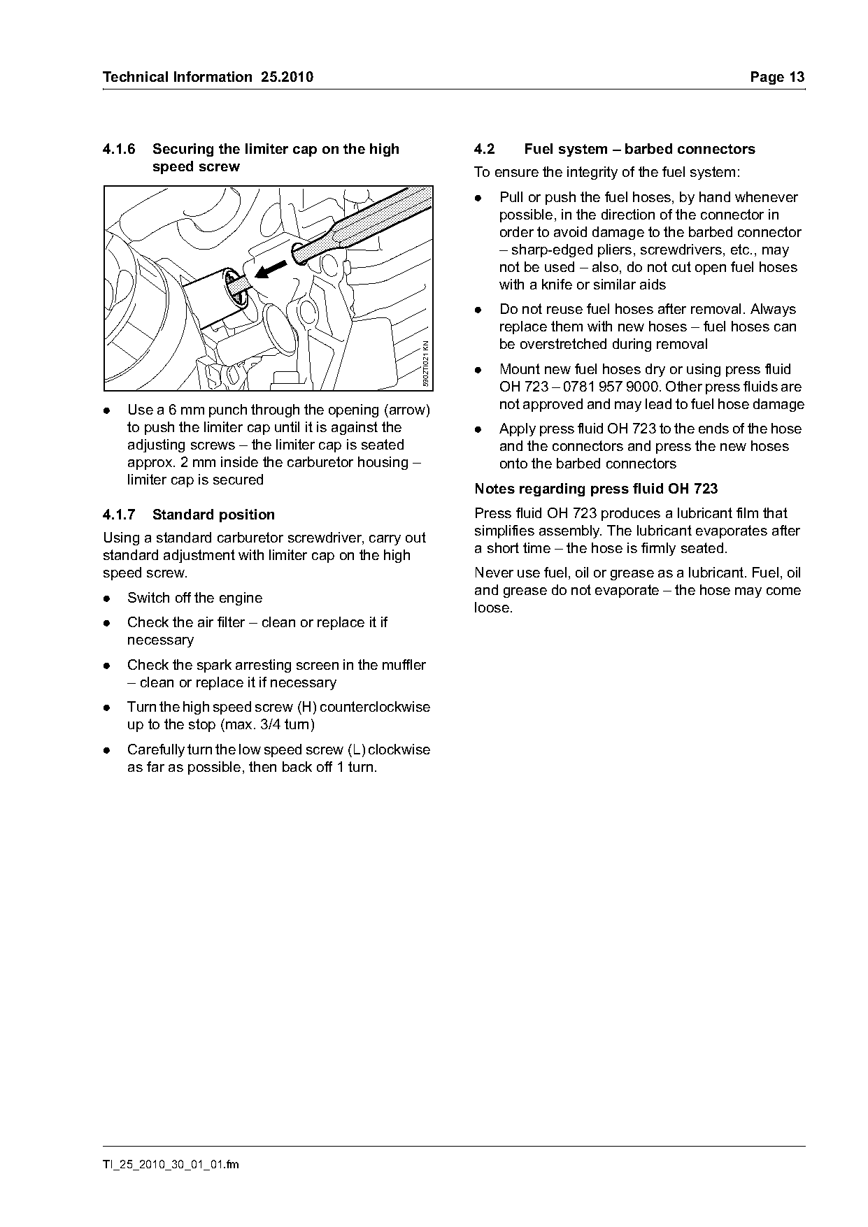
4.1.6   Securing the limiter cap on the high                       4.2      Fuel system – barbed connectors
        speed screw                                                To ensure the integrity of the fuel system:
                                                                   .     Pull or push the fuel hoses, by hand whenever
                                                                         possible, in the direction of the connector in
                                                                         order to avoid damage to the barbed connector
                                                                         – sharp-edged pliers, screwdrivers, etc., may
                                                                         not be used – also, do not cut open fuel hoses
                                                                         with a knife or similar aids
                                                                   .     Do not reuse fuel hoses after removal. Always
                                                                         replace them with new hoses – fuel hoses can
                                                                         be overstretched during removal

                                                    5902TI021 KN
                                                                   .     Mount new fuel hoses dry or using press fluid
                                                                         OH 723 – 0781 957 9000. Other press fluids are
.   Use a 6 mm punch through the opening (arrow)                         not approved and may lead to fuel hose damage
    to push the limiter cap until it is against the                .     Apply press fluid OH 723 to the ends of the hose
    adjusting screws – the limiter cap is seated                         and the connectors and press the new hoses
    approx. 2 mm inside the carburetor housing –                         onto the barbed connectors
    limiter cap is secured
                                                                   Notes regarding press fluid OH 723
4.1.7   Standard position                                          Press fluid OH 723 produces a lubricant film that
                                                                   simplifies assembly. The lubricant evaporates after
Using a standard carburetor screwdriver, carry out
                                                                   a short time – the hose is firmly seated.
standard adjustment with limiter cap on the high
speed screw.                                                       Never use fuel, oil or grease as a lubricant. Fuel, oil
                                                                   and grease do not evaporate – the hose may come
.   Switch off the engine
                                                                   loose.
.   Check the air filter – clean or replace it if
    necessary
.   Check the spark arresting screen in the muffler
    – clean or replace it if necessary
.   Turn the high speed screw (H) counterclockwise
    up to the stop (max. 3/4 turn)
.   Carefully turn the low speed screw (L) clockwise
    as far as possible, then back off 1 turn.

TI_25_2010_30_01_01.fm
Page 14 of 15
Text of page 14 — search, copy, screen readers
Page 14                                                                          Technical Information 25.2010

4.3    Tightening torques
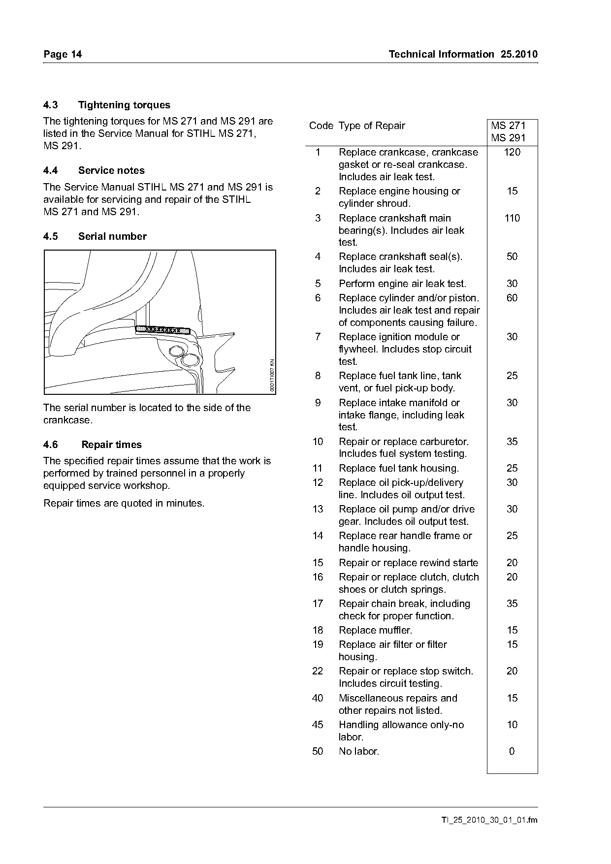
The tightening torques for MS 271 and MS 291 are                 Code Type of Repair                      MS 271
listed in the Service Manual for STIHL MS 271,                                                            MS 291
MS 291.
                                                                  1   Replace crankcase, crankcase          120
                                                                      gasket or re-seal crankcase.
4.4    Service notes
                                                                      Includes air leak test.
The Service Manual STIHL MS 271 and MS 291 is                     2   Replace engine housing or             15
available for servicing and repair of the STIHL                       cylinder shroud.
MS 271 and MS 291.
                                                                  3   Replace crankshaft main               110
                                                                      bearing(s). Includes air leak
4.5    Serial number
                                                                      test.
                                                                  4   Replace crankshaft seal(s).           50
                                                                      Includes air leak test.
                                                                  5   Perform engine air leak test.         30
                                                                  6   Replace cylinder and/or piston.       60
                                                                      Includes air leak test and repair
                                                                      of components causing failure.
                                                                  7   Replace ignition module or            30
                                                                      flywheel. Includes stop circuit
                                                                      test.
                                                  0001TI007 KN

                                                                  8   Replace fuel tank line, tank          25
                                                                      vent, or fuel pick-up body.
                                                                  9   Replace intake manifold or            30
The serial number is located to the side of the
                                                                      intake flange, including leak
crankcase.
                                                                      test.
4.6     Repair times                                             10   Repair or replace carburetor.         35
                                                                      Includes fuel system testing.
The specified repair times assume that the work is
                                                                 11   Replace fuel tank housing.            25
performed by trained personnel in a properly
equipped service workshop.                                       12   Replace oil pick-up/delivery          30
                                                                      line. Includes oil output test.
Repair times are quoted in minutes.
                                                                 13   Replace oil pump and/or drive         30
                                                                      gear. Includes oil output test.
                                                                 14   Replace rear handle frame or          25
                                                                      handle housing.
                                                                 15   Repair or replace rewind starte       20
                                                                 16   Repair or replace clutch, clutch      20
                                                                      shoes or clutch springs.
                                                                 17   Repair chain break, including         35
                                                                      check for proper function.
                                                                 18   Replace muffler.                      15
                                                                 19   Replace air filter or filter          15
                                                                      housing.
                                                                 22   Repair or replace stop switch.        20
                                                                      Includes circuit testing.
                                                                 40   Miscellaneous repairs and             15
                                                                      other repairs not listed.
                                                                 45   Handling allowance only-no            10
                                                                      labor.
                                                                 50   No labor.                              0

                                                                                             TI_25_2010_30_01_01.fm
Page 15 of 15

Text of page 15 — search, copy, screen readers
Technical Information 25.2010                                 Page 15

© ANDREAS STIHL AG & Co. KG, 2010   Technical Documentation
                                    D1/MTK-bl

TI_25_2010_30_01_01.fm
Most of these PDFs embed fonts with a shifted character map, so the text above was recovered rather than copied — read it as a faithful but imperfect transcription, and treat the page image above each block as the authority where the two disagree — the figures exist only there, because they are vector drawings that text extraction cannot keep.