Technical Information · issue 28 of 2010
New pressurized water tank; Summary
IssueTI 28/2010
Part changes (1)
| Was | Becomes | What the bulletin says |
|---|---|---|
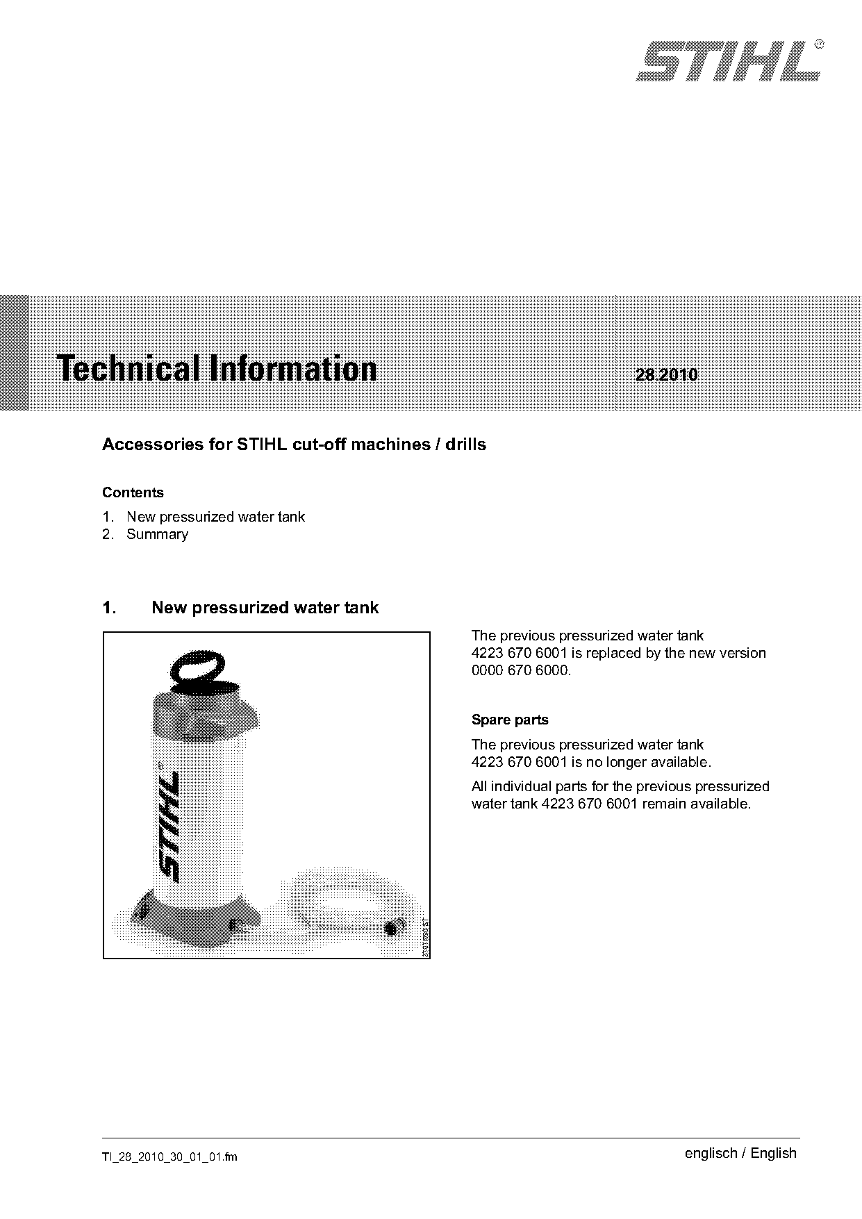
| 4223 670 6001 | 0000 670 6000 | New pressurized water tank The previous pressurized water tank 4223 670 6001 is replaced by the new version 0000 670 6000. |
Full text
Page 1 of 6
Text of page 1 — search, copy, screen readers
STIH)

Technical Information                                                    28.2010

  Accessories for STIHL cut-off machines / drills

  Contents
  1. New pressurized water tank
  2. Summary

  1.     New pressurized water tank
                                               The previous pressurized water tank
                                               4223 670 6001 is replaced by the new version
                                               0000 670 6000.

                                               Spare parts
                                               The previous pressurized water tank
                                               4223 670 6001 is no longer available.
                                               All individual parts for the previous pressurized
                                               water tank 4223 670 6001 remain available.

  TI_28_2010_30_01_01.fm                                                          englisch / English
Page 2 of 6
Text of page 2 — search, copy, screen readers
Page 2                                                                                       Technical Information 28.2010

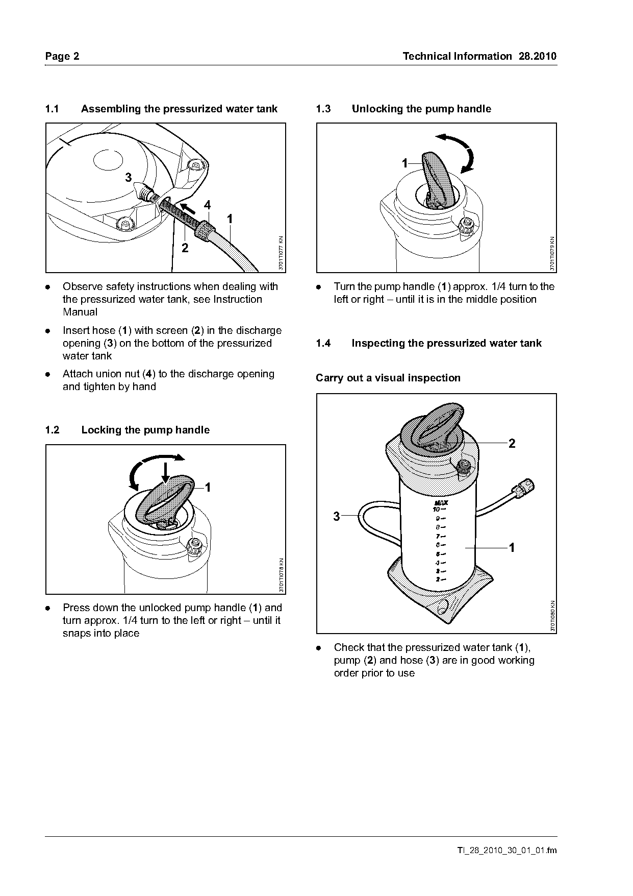
1.1       Assembling the pressurized water tank                         1.3       Unlocking the pump handle

                                                                                             1
                     3

                                        4
                                             1

                                                         3701TI077 KN

                                                                                                                              3701TI079 KN
                                  2

.     Observe safety instructions when dealing with                     .     Turn the pump handle (1) approx. 1/4 turn to the
      the pressurized water tank, see Instruction                             left or right – until it is in the middle position
      Manual
.     Insert hose (1) with screen (2) in the discharge
      opening (3) on the bottom of the pressurized                      1.4       Inspecting the pressurized water tank
      water tank
.     Attach union nut (4) to the discharge opening                     Carry out a visual inspection
      and tighten by hand

1.2       Locking the pump handle
                                                                                                                     2


                                                                                                                     1
                                                         3701TI078 KN

                                                                                                                              370TI080 KN

.     Press down the unlocked pump handle (1) and
      turn approx. 1/4 turn to the left or right – until it
      snaps into place
                                                                        .     Check that the pressurized water tank (1),
                                                                              pump (2) and hose (3) are in good working
                                                                              order prior to use

                                                                                                         TI_28_2010_30_01_01.fm
Page 3 of 6
Text of page 3 — search, copy, screen readers
Technical Information 28.2010                                                                                     Page 3

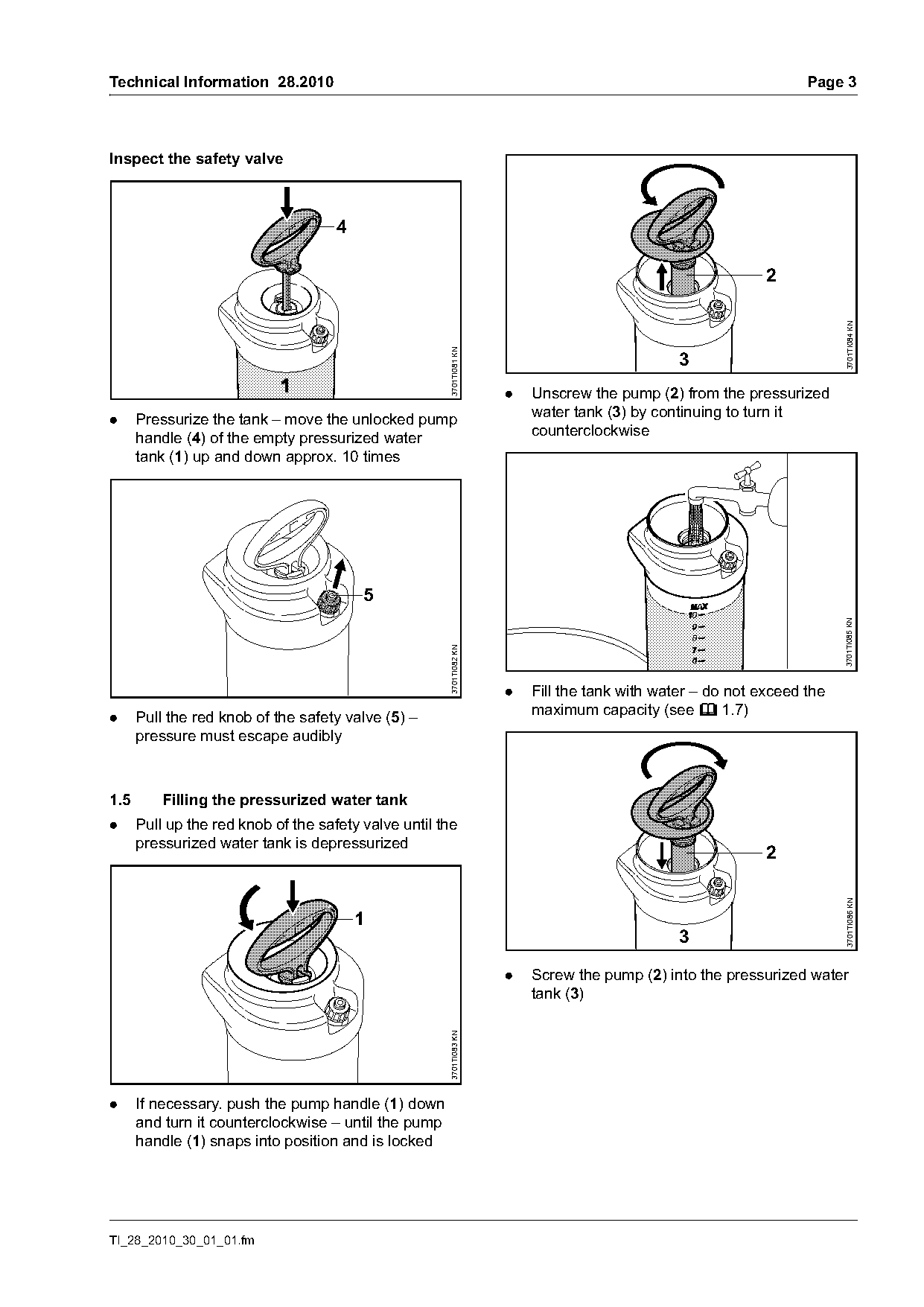
Inspect the safety valve


                                                                                                                        3701TI084 KN
                                                      3701TI081 KN
                                                                                               3
                                                                     .   Unscrew the pump (2) from the pressurized
                                                                         water tank (3) by continuing to turn it
.     Pressurize the tank – move the unlocked pump
                                                                         counterclockwise
      handle (4) of the empty pressurized water
      tank (1) up and down approx. 10 times


                                                                                                                        3701TI085 KN
                                                      3701TI082 KN

                                                                     .   Fill the tank with water – do not exceed the
                                                                         maximum capacity (see b 1.7)
.     Pull the red knob of the safety valve (5) –
      pressure must escape audibly

1.5       Filling the pressurized water tank
.     Pull up the red knob of the safety valve until the
      pressurized water tank is depressurized
                                                                                                            2           3701TI086 KN

                                         1
                                                                                               3

                                                                     .   Screw the pump (2) into the pressurized water
                                                                         tank (3)
                                                      3701TI083 KN

.     If necessary. push the pump handle (1) down
      and turn it counterclockwise – until the pump
      handle (1) snaps into position and is locked

TI_28_2010_30_01_01.fm
Page 4 of 6
Text of page 4 — search, copy, screen readers
Page 4                                                                                     Technical Information 28.2010

                                                                      After use
                                                                      .     Disconnect the quick-action coupling from the
                                     1                                      cut-off machine or drill used
                                                                      .     Pull up the red knob of the safety valve until the
                                                                            pressurized water tank is depressurized
                                                                      .     Empty the pressurized water tank
                                                                      .     For drying and storage, keep the pressurized
                                                                            water tank in a dry, frost-free environment where

                                                       3701TI087 KN
                                                                            it is shielded from the sun's rays
                                                                      .     If necessary, unscrew the hose and clean the
                                                                            screen under running water
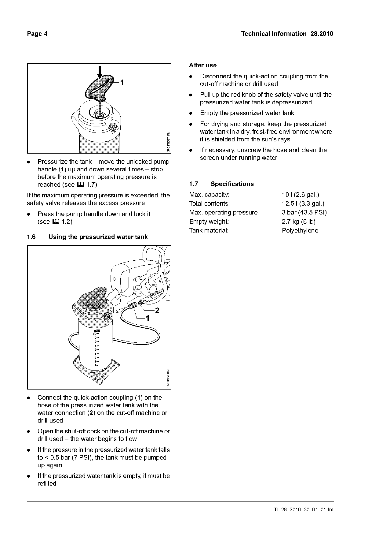
.     Pressurize the tank – move the unlocked pump
      handle (1) up and down several times – stop
      before the maximum operating pressure is
      reached (see b 1.7)                                             1.7       Specifications
If the maximum operating pressure is exceeded, the                    Max. capacity:                       10 l (2.6 gal.)
safety valve releases the excess pressure.                            Total contents:                      12.5 l (3.3 gal.)
.     Press the pump handle down and lock it                          Max. operating pressure              3 bar (43.5 PSI)
      (see b 1.2)                                                     Empty weight:                        2.7 kg (6 lb)
                                                                      Tank material:                       Polyethylene
1.6       Using the pressurized water tank

                                                   2
                                               1
                                                       370TI088 KN

.     Connect the quick-action coupling (1) on the
      hose of the pressurized water tank with the
      water connection (2) on the cut-off machine or
      drill used
.     Open the shut-off cock on the cut-off machine or
      drill used – the water begins to flow
.     If the pressure in the pressurized water tank falls
      to < 0.5 bar (7 PSI), the tank must be pumped
      up again
.     If the pressurized water tank is empty, it must be
      refilled

                                                                                                       TI_28_2010_30_01_01.fm
Page 5 of 6
Text of page 5 — search, copy, screen readers
Technical Information 28.2010                                                                             Page 5

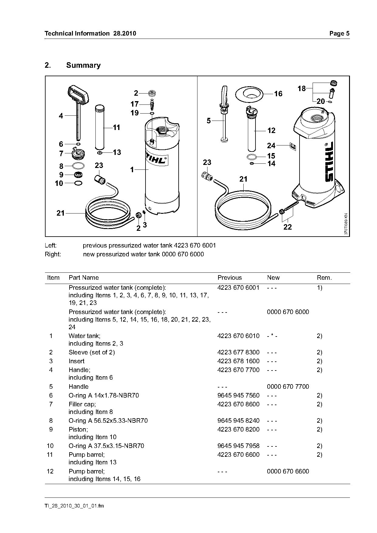
2.        Summary

                                                                                                18
                                  2                                                   16
                                 17                                                                  20
     4                           19
                                                               5
                           11                                                       12
     6                                                                              24
     7                     13                                                       15
                    23                                       23                     14
      8                          1
      9
                                                                           21
     10


                                                                                                              370TI089 KN
                                     23                                                    22

Left:          previous pressurized water tank 4223 670 6001
Right:         new pressurized water tank 0000 670 6000

Item      Part Name                                                 Previous        New              Rem.
          Pressurized water tank (complete):                        4223 670 6001   ---              1)
          including Items 1, 2, 3, 4, 6, 7, 8, 9, 10, 11, 13, 17,
          19, 21, 23
          Pressurized water tank (complete):                        ---             0000 670 6000
          including Items 5, 12, 14, 15, 16, 18, 20, 21, 22, 23,
          24
 1        Water tank;                                               4223 670 6010   -*-              2)
          including Items 2, 3
 2        Sleeve (set of 2)                                         4223 677 8300   ---              2)
 3        Insert                                                    4223 678 1600   ---              2)
 4        Handle;                                                   4223 670 7700   ---              2)
          including Item 6
 5        Handle                                                    ---             0000 670 7700
 6        O-ring A 14x1.78-NBR70                                    9645 945 7560   ---              2)
 7        Filler cap;                                               4223 670 8600   ---              2)
          including Item 8
 8        O-ring A 56.52x5.33-NBR70                                 9645 945 8240   ---              2)
 9        Piston;                                                   4223 670 8200   ---              2)
          including Item 10
10        O-ring A 37.5x3.15-NBR70                                  9645 945 7958   ---              2)
11        Pump barrel;                                              4223 670 6600   ---              2)
          including Item 13
12        Pump barrel;                                              ---             0000 670 6600
          including Items 14, 15, 16

TI_28_2010_30_01_01.fm
Page 6 of 6
Text of page 6 — search, copy, screen readers
Page 6                                                                     Technical Information 28.2010

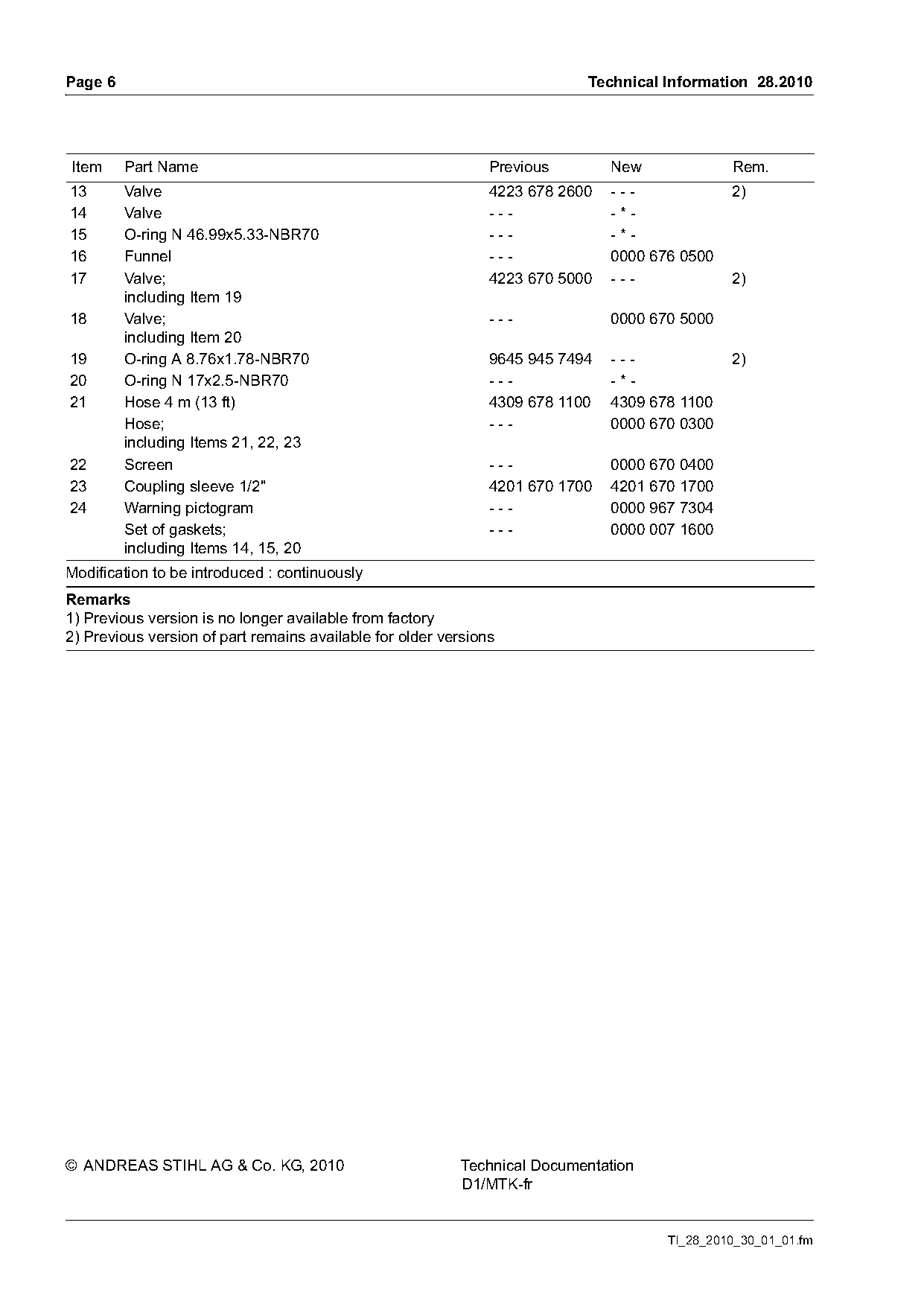
Item     Part Name                                             Previous        New             Rem.
13       Valve                                                 4223 678 2600   ---             2)
14       Valve                                                 ---             -*-
15       O-ring N 46.99x5.33-NBR70                             ---             -*-
16       Funnel                                                ---             0000 676 0500
17       Valve;                                                4223 670 5000   ---             2)
         including Item 19
18       Valve;                                                ---             0000 670 5000
         including Item 20
19       O-ring A 8.76x1.78-NBR70                              9645 945 7494   ---             2)
20       O-ring N 17x2.5-NBR70                                 ---             -*-
21       Hose 4 m (13 ft)                                      4309 678 1100   4309 678 1100
         Hose;                                                 ---             0000 670 0300
         including Items 21, 22, 23
22       Screen                                                ---             0000 670 0400
23       Coupling sleeve 1/2"                                  4201 670 1700   4201 670 1700
24       Warning pictogram                                     ---             0000 967 7304
         Set of gaskets;                                       ---             0000 007 1600
         including Items 14, 15, 20
Modification to be introduced : continuously
Remarks
1) Previous version is no longer available from factory
2) Previous version of part remains available for older versions

© ANDREAS STIHL AG & Co. KG, 2010                          Technical Documentation
                                                           D1/MTK-fr

                                                                                      TI_28_2010_30_01_01.fm
Most of these PDFs embed fonts with a shifted character map, so the text above was recovered rather than copied — read it as a faithful but imperfect transcription, and treat the page image above each block as the authority where the two disagree — the figures exist only there, because they are vector drawings that text extraction cannot keep.