Technical Information · issue 40 of 2010
New brushcutter/clearing saw STIHL FS 460 C - EM
Full text
Page 1 of 28
Text of page 1 — search, copy, screen readers
STIH)

Technical Information                                       40.2010

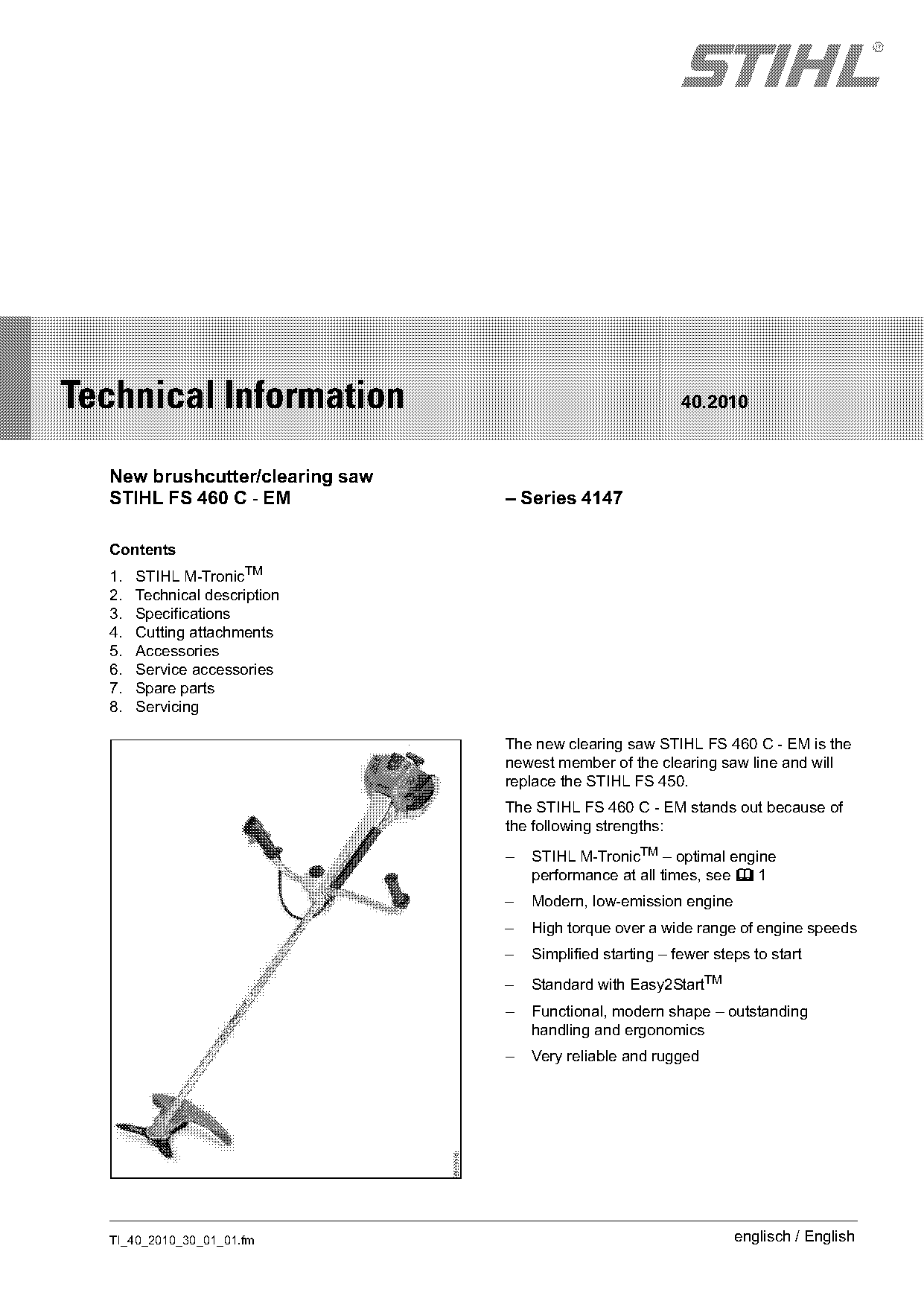
  New brushcutter/clearing saw
  STIHL FS 460 C - EM            – Series 4147

  Contents
  1.   STIHL M-TronicTM
  2.   Technical description
  3.   Specifications
  4.   Cutting attachments
  5.   Accessories
  6.   Service accessories
  7.   Spare parts
  8.   Servicing

                                 The new clearing saw STIHL FS 460 C - EM is the
                                 newest member of the clearing saw line and will
                                 replace the STIHL FS 450.
                                 The STIHL FS 460 C - EM stands out because of
                                 the following strengths:
                                 –   STIHL M-TronicTM – optimal engine
                                     performance at all times, see b 1
                                 –   Modern, low-emission engine
                                 –   High torque over a wide range of engine speeds
                                 –   Simplified starting – fewer steps to start
                                 –   Standard with Easy2StartTM
                                 –   Functional, modern shape – outstanding
                                     handling and ergonomics
                                 –   Very reliable and rugged

  TI_40_2010_30_01_01.fm                                            englisch / English
Page 2 of 28
Text of page 2 — search, copy, screen readers
Page 2                                                                       Technical Information 40.2010

The new clearing saw is ideally suited for                1.1     Functional description
professional users in landscaping and forestry. The
scope of application extends from mowing and
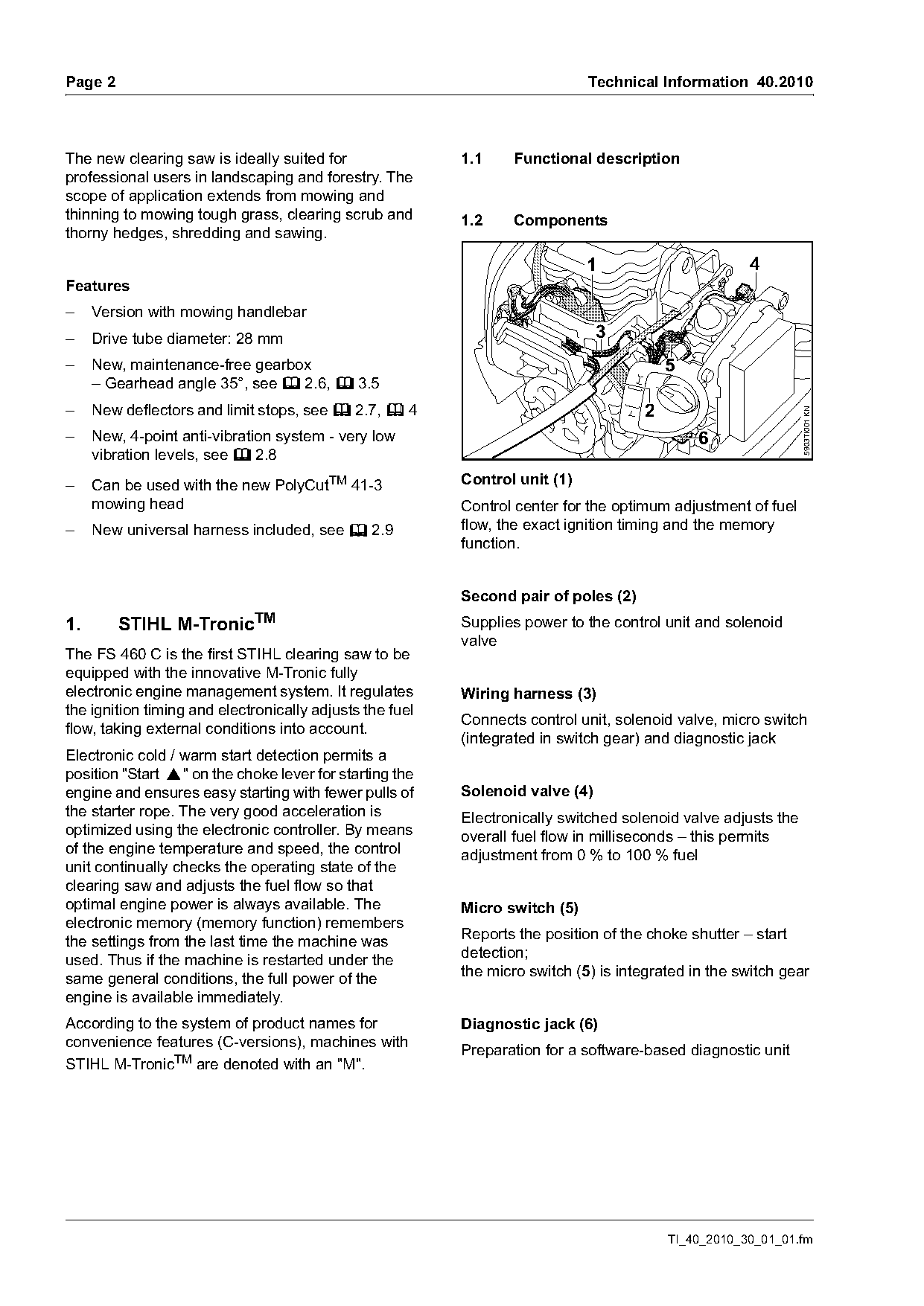
thinning to mowing tough grass, clearing scrub and        1.2     Components
thorny hedges, shredding and sawing.

                                                                             1                       4
Features
–    Version with mowing handlebar
–    Drive tube diameter: 28 mm                                                3
–    New, maintenance-free gearbox                                                       5
     – Gearhead angle 35°, see b 2.6, b 3.5
–    New deflectors and limit stops, see b 2.7, b 4                                  2

                                                                                                               5903TI001 KN
–    New, 4-point anti-vibration system - very low                                            6
     vibration levels, see b 2.8
–    Can be used with the new PolyCutTM 41-3              Control unit (1)
     mowing head                                          Control center for the optimum adjustment of fuel
–    New universal harness included, see b 2.9            flow, the exact ignition timing and the memory
                                                          function.

                                                          Second pair of poles (2)
1.       STIHL M-TronicTM                                 Supplies power to the control unit and solenoid
                                                          valve
The FS 460 C is the first STIHL clearing saw to be
equipped with the innovative M-Tronic fully
electronic engine management system. It regulates         Wiring harness (3)
the ignition timing and electronically adjusts the fuel
                                                          Connects control unit, solenoid valve, micro switch
flow, taking external conditions into account.
                                                          (integrated in switch gear) and diagnostic jack
Electronic cold / warm start detection permits a
position "Start }" on the choke lever for starting the
engine and ensures easy starting with fewer pulls of      Solenoid valve (4)
the starter rope. The very good acceleration is           Electronically switched solenoid valve adjusts the
optimized using the electronic controller. By means       overall fuel flow in milliseconds – this permits
of the engine temperature and speed, the control          adjustment from 0 % to 100 % fuel
unit continually checks the operating state of the
clearing saw and adjusts the fuel flow so that
optimal engine power is always available. The             Micro switch (5)
electronic memory (memory function) remembers
the settings from the last time the machine was           Reports the position of the choke shutter – start
used. Thus if the machine is restarted under the          detection;
same general conditions, the full power of the            the micro switch (5) is integrated in the switch gear
engine is available immediately.
According to the system of product names for              Diagnostic jack (6)
convenience features (C-versions), machines with
                                                          Preparation for a software-based diagnostic unit
STIHL M-TronicTM are denoted with an "M".

                                                                                         TI_40_2010_30_01_01.fm
Page 3 of 28
Text of page 3 — search, copy, screen readers
Technical Information 40.2010                                                                              Page 3

1.2.1   Starting                                            1.2.3   Acceleration
Set the choke lever to } (Start) – choke shutter is         If the control unit detects that the engine is being
closed. Simultaneously, the micro switch on the             accelerated, the ignition timing is set earlier and the
switching device is closed. During starting and if the      fuel flow is increased – the fuel-air mixture is
engine is running, the control unit is powered via the      enriched. Optimal, spontaneous acceleration.
second pair of poles.
The following processes occur within milliseconds.
                                                            1.2.4   Full throttle
The microprocessor detects that the micro switch
has been actuated and thus the choke shutter is             A regulating cycle only starts if the clearing saw is
closed and computes the necessary amount of fuel            operated for approximately 2 seconds under
and the ignition timing for the start.                      constant conditions.
During starting, the fuel-air mixture in the carburetor     The solenoid valve closes for approx. 0.1 seconds –
is highly concentrated ("enriched") – a large quantity      the current fuel-air mixture is made leaner.
of fuel flows through the solenoid valve. After initial     The speed change due to the brief leaning of the mix
combustion, the quantity of fuel is reduced. The            is so slight as to be unnoticable to the user.
engine does not stall out because the fuel-air
mixture is too rich; it keeps running and can be            The resulting engine speed pattern is analyzed by
accelerated immediately. After the throttle trigger is      the microprocessor.
actuated, the choke shutter and micro switch open
and the choke lever jumps to the operating
position F . The control unit receives the information      The following results are possible:
"choke shutter open" and the microprocessor                 Engine speed increases
adjusts the amount of fuel.
                                                            .   The mix was too rich before the solenoid valve
                                                                closed – the fuel flow is reduced for next phase
                                                                of operation
1.2.2   Idle
                                                            Engine speed decreases
The target idle speed is controlled by adjusting the
                                                            .   The mix was too lean before the solenoid valve
ignition timing and the fuel flow.
                                                                closed – the fuel flow is increased for the next
The engine speed can be influenced instantly by                 phase of operation
adjusting the ignition timing. Changing the fuel flow
                                                            Engine speed does not change
only influences the engine speed after 5 to
10 revolutions of the crankshaft.                           .   The current carburetor setting is optimal – the
                                                                current setting will be maintained
For this reason, to establish steady idling, the
ignition timing is adjusted first and then the fuel flow.
The fuel flow control is designed so that the target
idle speed is obtained with the target ignition timing.     1.2.5   Cut-off speed
                                                            The cut-off speed is kept constant by controling the
                                                            fuel-air mixture and the ignition timing.

TI_40_2010_30_01_01.fm
Page 4 of 28
Text of page 4 — search, copy, screen readers
Page 4                                                                          Technical Information 40.2010

1.2.6    Advantages                                        2.        Technical description

Simplified starting
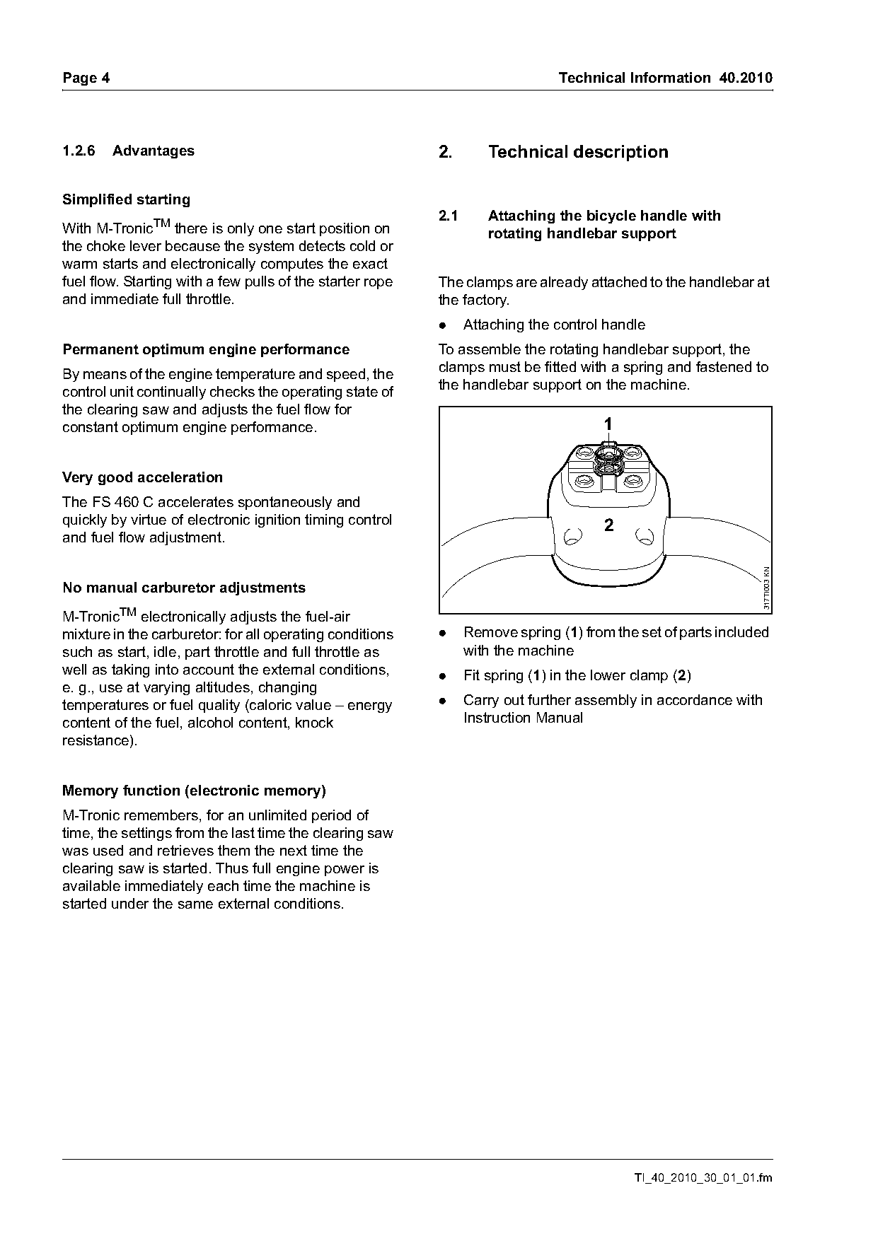
                                                           2.1       Attaching the bicycle handle with
With M-TronicTM there is only one start position on                  rotating handlebar support
the choke lever because the system detects cold or
warm starts and electronically computes the exact
fuel flow. Starting with a few pulls of the starter rope   The clamps are already attached to the handlebar at
and immediate full throttle.                               the factory.
                                                           .     Attaching the control handle
Permanent optimum engine performance                       To assemble the rotating handlebar support, the
By means of the engine temperature and speed, the          clamps must be fitted with a spring and fastened to
control unit continually checks the operating state of     the handlebar support on the machine.
the clearing saw and adjusts the fuel flow for
constant optimum engine performance.                                                   1

Very good acceleration
The FS 460 C accelerates spontaneously and
quickly by virtue of electronic ignition timing control                                2
and fuel flow adjustment.

                                                                                                                317TI003 KN
No manual carburetor adjustments
M-TronicTM electronically adjusts the fuel-air
mixture in the carburetor: for all operating conditions    .     Remove spring (1) from the set of parts included
such as start, idle, part throttle and full throttle as          with the machine
well as taking into account the external conditions,       .     Fit spring (1) in the lower clamp (2)
e. g., use at varying altitudes, changing
temperatures or fuel quality (caloric value – energy       .     Carry out further assembly in accordance with
content of the fuel, alcohol content, knock                      Instruction Manual
resistance).

Memory function (electronic memory)
M-Tronic remembers, for an unlimited period of
time, the settings from the last time the clearing saw
was used and retrieves them the next time the
clearing saw is started. Thus full engine power is
available immediately each time the machine is
started under the same external conditions.

                                                                                            TI_40_2010_30_01_01.fm
Page 5 of 28
Text of page 5 — search, copy, screen readers
Technical Information 40.2010                                                                                     Page 5

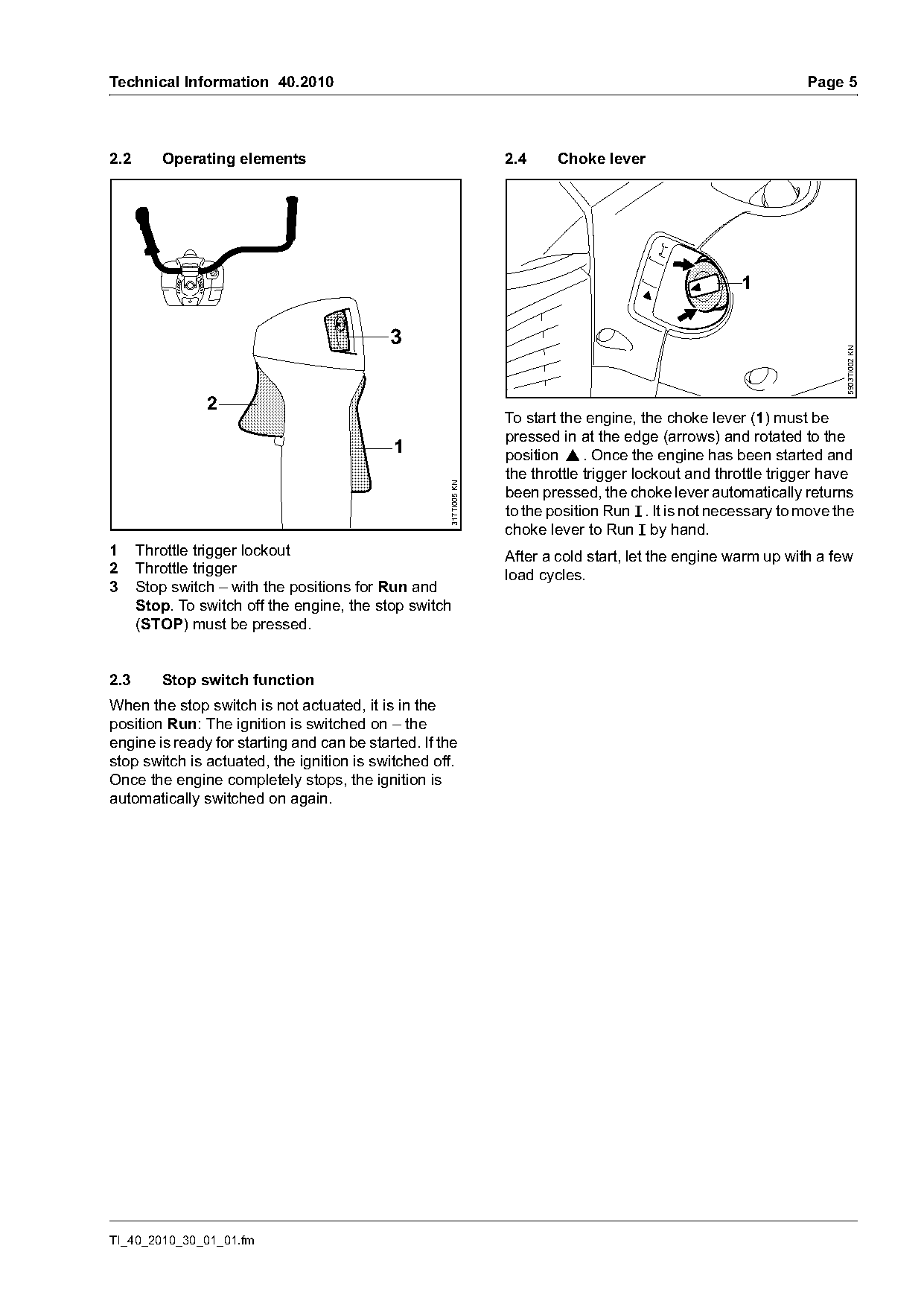
2.2      Operating elements                                        2.4     Choke lever


                                                                                                                        5903TI002 KN
                2
                                                                   To start the engine, the choke lever (1) must be
                                                                   pressed in at the edge (arrows) and rotated to the
                                            1                      position }. Once the engine has been started and
                                                                   the throttle trigger lockout and throttle trigger have
                                                     317TI005 KN

                                                                   been pressed, the choke lever automatically returns
                                                                   to the position Run F . It is not necessary to move the
                                                                   choke lever to Run F by hand.
1     Throttle trigger lockout                                     After a cold start, let the engine warm up with a few
2     Throttle trigger                                             load cycles.
3     Stop switch – with the positions for Run and
      Stop. To switch off the engine, the stop switch
      (STOP) must be pressed.

2.3      Stop switch function
When the stop switch is not actuated, it is in the
position Run: The ignition is switched on – the
engine is ready for starting and can be started. If the
stop switch is actuated, the ignition is switched off.
Once the engine completely stops, the ignition is
automatically switched on again.

TI_40_2010_30_01_01.fm
Page 6 of 28
Text of page 6 — search, copy, screen readers
Page 6                                                                             Technical Information 40.2010

2.5      Summer and winter operation

                                                                               3
2.5.1    At temperatures below +50 °F (+10 °C)

Pre-heat carburetor
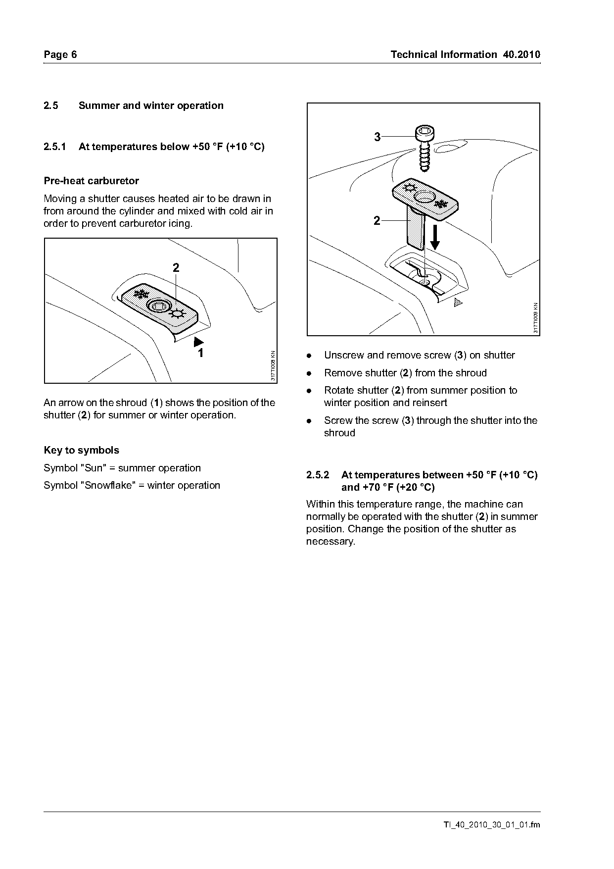
Moving a shutter causes heated air to be drawn in
from around the cylinder and mixed with cold air in
order to prevent carburetor icing.                                             2


                                                                                                                  317TI009 KN
                                  1                             .   Unscrew and remove screw (3) on shutter
                                                  317TI008 KN

                                                                .   Remove shutter (2) from the shroud
                                                                .   Rotate shutter (2) from summer position to
An arrow on the shroud (1) shows the position of the                winter position and reinsert
shutter (2) for summer or winter operation.
                                                                .   Screw the screw (3) through the shutter into the
                                                                    shroud
Key to symbols
Symbol "Sun" = summer operation
                                                                2.5.2   At temperatures between +50 °F (+10 °C)
Symbol "Snowflake" = winter operation                                   and +70 °F (+20 °C)
                                                                Within this temperature range, the machine can
                                                                normally be operated with the shutter (2) in summer
                                                                position. Change the position of the shutter as
                                                                necessary.

                                                                                              TI_40_2010_30_01_01.fm
Page 7 of 28
Text of page 7 — search, copy, screen readers
Technical Information 40.2010                                                                                      Page 7

2.5.3   At temperatures above +70 °F (+20 °C)                     2.5.5   Cover plate kit

                                                                                                        2
                              2


                                                    317TI010 KN

                                                                                                                        317TI011 KN
                                                                                                               4

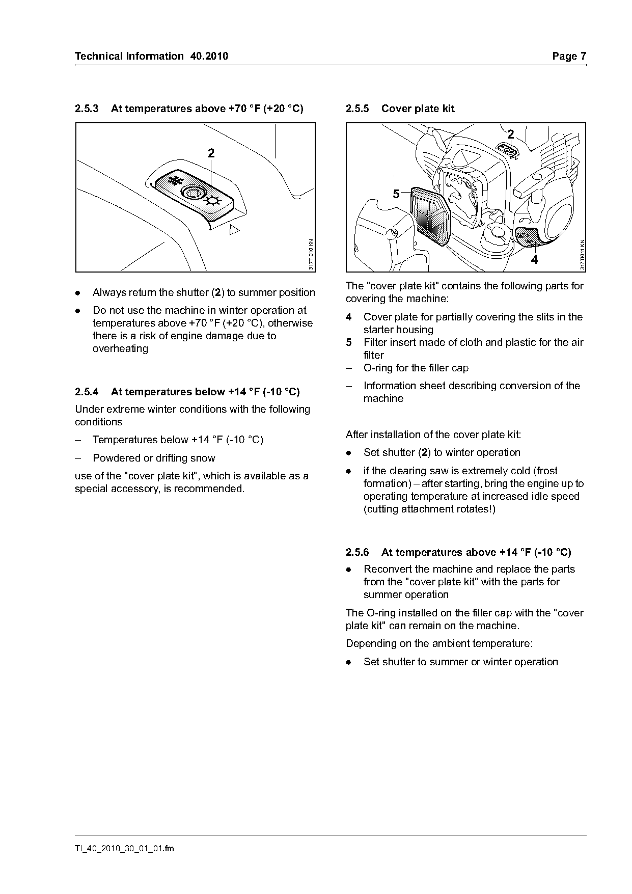
                                                                  The "cover plate kit" contains the following parts for
.   Always return the shutter (2) to summer position
                                                                  covering the machine:
.   Do not use the machine in winter operation at
                                                                  4   Cover plate for partially covering the slits in the
    temperatures above +70 °F (+20 °C), otherwise
                                                                      starter housing
    there is a risk of engine damage due to
                                                                  5   Filter insert made of cloth and plastic for the air
    overheating
                                                                      filter
                                                                  –   O-ring for the filler cap
                                                                  –   Information sheet describing conversion of the
2.5.4   At temperatures below +14 °F (-10 °C)
                                                                      machine
Under extreme winter conditions with the following
conditions
–   Temperatures below +14 °F (-10 °C)                            After installation of the cover plate kit:
                                                                  .   Set shutter (2) to winter operation
–   Powdered or drifting snow
                                                                  .   if the clearing saw is extremely cold (frost
use of the "cover plate kit", which is available as a
                                                                      formation) – after starting, bring the engine up to
special accessory, is recommended.
                                                                      operating temperature at increased idle speed
                                                                      (cutting attachment rotates!)

                                                                  2.5.6   At temperatures above +14 °F (-10 °C)
                                                                  .   Reconvert the machine and replace the parts
                                                                      from the "cover plate kit" with the parts for
                                                                      summer operation
                                                                  The O-ring installed on the filler cap with the "cover
                                                                  plate kit" can remain on the machine.
                                                                  Depending on the ambient temperature:
                                                                  .   Set shutter to summer or winter operation

TI_40_2010_30_01_01.fm
Page 8 of 28
Text of page 8 — search, copy, screen readers
Page 8                                                                          Technical Information 40.2010

2.6      Gearbox                                            2.7       New deflectors and limit stops
A new, maintenance-free gearbox with a gearhead
angle of 35° is used.

Gearhead angle 35°                                                1                       2

                                                                  3                        4
                                              317TI012 KN

                                                                                                                  317TI037 KN
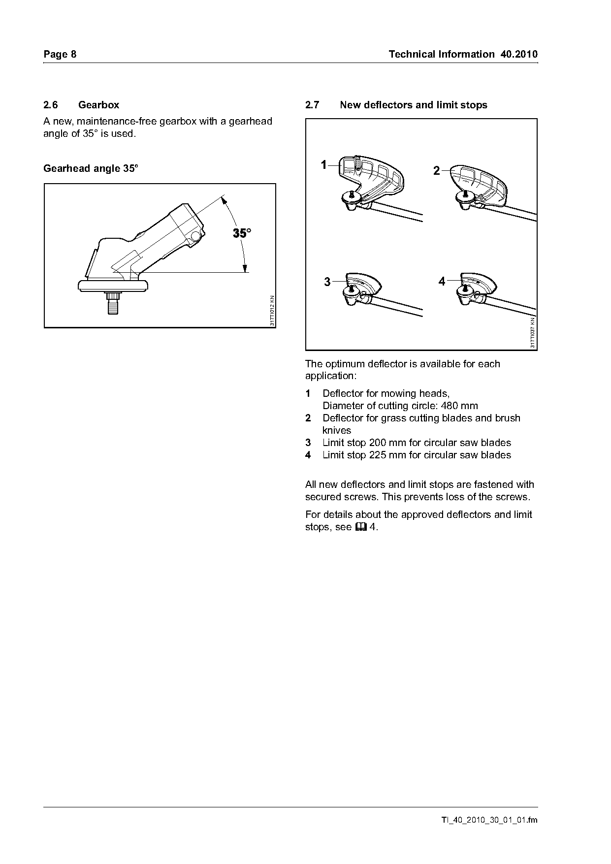
                                                            The optimum deflector is available for each
                                                            application:
                                                            1     Deflector for mowing heads,
                                                                  Diameter of cutting circle: 480 mm
                                                            2     Deflector for grass cutting blades and brush
                                                                  knives
                                                            3     Limit stop 200 mm for circular saw blades
                                                            4     Limit stop 225 mm for circular saw blades

                                                            All new deflectors and limit stops are fastened with
                                                            secured screws. This prevents loss of the screws.
                                                            For details about the approved deflectors and limit
                                                            stops, see b 4.

                                                                                              TI_40_2010_30_01_01.fm
Page 9 of 28
Text of page 9 — search, copy, screen readers
Technical Information 40.2010                                                                               Page 9

2.8     4-point anti-vibration system                           2.9      New full universal harnesses

                                                  317TI017 KN
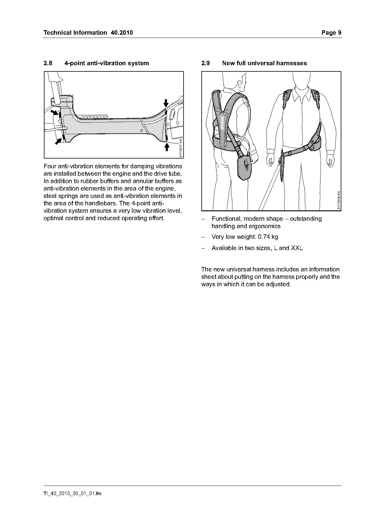
Four anti-vibration elements for damping vibrations
are installed between the engine and the drive tube,
In addition to rubber buffers and annular buffers as
anti-vibration elements in the area of the engine,

                                                                                                                 317TI018 KN
steel springs are used as anti-vibration elements in
the area of the handlebars. The 4-point anti-
vibration system ensures a very low vibration level,
optimal control and reduced operating effort.                   –     Functional, modern shape – outstanding
                                                                      handling and ergonomics
                                                                –     Very low weight: 0.74 kg
                                                                –     Available in two sizes, L and XXL

                                                                The new universal harness includes an information
                                                                sheet about putting on the harness properly and the
                                                                ways in which it can be adjusted.

TI_40_2010_30_01_01.fm
Page 10 of 28
Text of page 10 — search, copy, screen readers
Page 10                                                                   Technical Information 40.2010

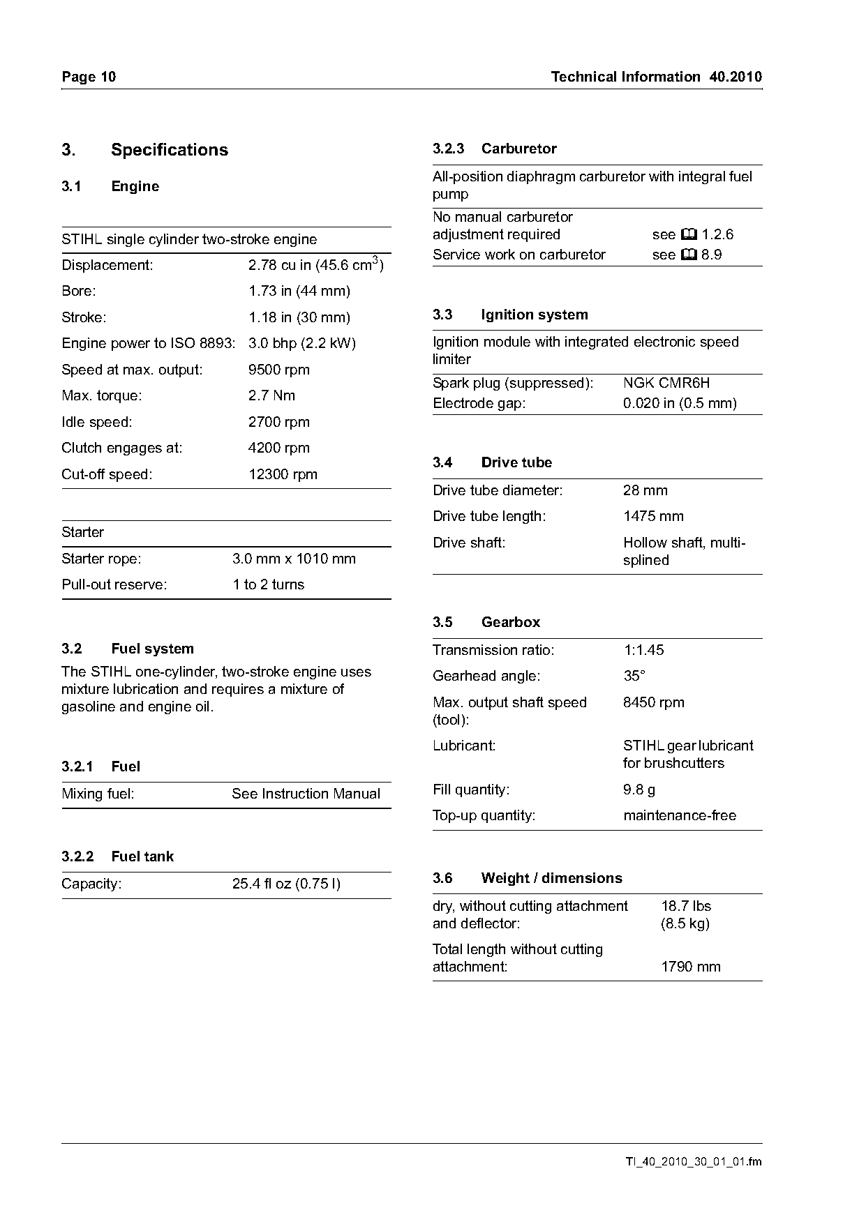
3.        Specifications                             3.2.3   Carburetor
                                                     All-position diaphragm carburetor with integral fuel
3.1       Engine                                     pump
                                                     No manual carburetor
STIHL single cylinder two-stroke engine              adjustment required                  see b 1.2.6
                                                     Service work on carburetor           see b 8.9
Displacement:                2.78 cu in (45.6 cm3)
Bore:                        1.73 in (44 mm)
Stroke:                      1.18 in (30 mm)         3.3     Ignition system

Engine power to ISO 8893: 3.0 bhp (2.2 kW)           Ignition module with integrated electronic speed
                                                     limiter
Speed at max. output:        9500 rpm
                                                     Spark plug (suppressed):       NGK CMR6H
Max. torque:                 2.7 Nm                  Electrode gap:                 0.020 in (0.5 mm)
Idle speed:                  2700 rpm
Clutch engages at:           4200 rpm
                                                     3.4     Drive tube
Cut-off speed:               12300 rpm
                                                     Drive tube diameter:           28 mm
                                                     Drive tube length:             1475 mm
Starter
                                                     Drive shaft:                   Hollow shaft, multi-
Starter rope:              3.0 mm x 1010 mm                                         splined
Pull-out reserve:          1 to 2 turns

                                                     3.5     Gearbox
3.2       Fuel system                                Transmission ratio:            1:1.45
The STIHL one-cylinder, two-stroke engine uses       Gearhead angle:                35°
mixture lubrication and requires a mixture of
gasoline and engine oil.                             Max. output shaft speed        8450 rpm
                                                     (tool):
                                                     Lubricant:                     STIHL gear lubricant
3.2.1     Fuel                                                                      for brushcutters

Mixing fuel:               See Instruction Manual    Fill quantity:                 9.8 g
                                                     Top-up quantity:               maintenance-free

3.2.2     Fuel tank
Capacity:                  25.4 fl oz (0.75 l)       3.6     Weight / dimensions
                                                     dry, without cutting attachment        18.7 lbs
                                                     and deflector:                         (8.5 kg)
                                                     Total length without cutting
                                                     attachment:                            1790 mm

                                                                                    TI_40_2010_30_01_01.fm
Page 11 of 28
Text of page 11 — search, copy, screen readers
Technical Information 40.2010                                                                                  Page 11

4.         Cutting attachments                                       4.2       Grass cutting blades, brush knives and
                                                                               deflector
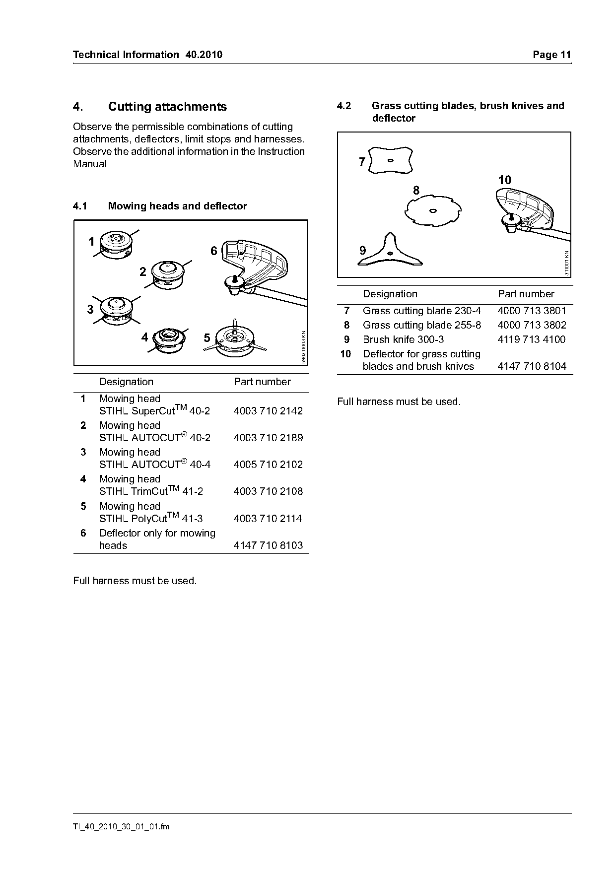
Observe the permissible combinations of cutting
attachments, deflectors, limit stops and harnesses.
Observe the additional information in the Instruction
Manual                                                                     7
                                                                                                         10
                                                                                       8
4.1        Mowing heads and deflector

      1
                                    6                                      9

                                                                                                                       3TI001 KN
                  2
                                                                           Designation                   Part number
     3                                                                7    Grass cutting blade 230-4     4000 713 3801
                                                                      8    Grass cutting blade 255-8     4000 713 3802
                   4
                                                      5903TI003 KN

                                5                                     9    Brush knife 300-3             4119 713 4100
                                                                     10    Deflector for grass cutting
                                                                           blades and brush knives       4147 710 8104
          Designation                   Part number
 1        Mowing head                                                Full harness must be used.
          STIHL SuperCutTM 40-2         4003 710 2142
 2        Mowing head
          STIHL AUTOCUT® 40-2           4003 710 2189
 3        Mowing head
          STIHL AUTOCUT® 40-4           4005 710 2102
 4        Mowing head
          STIHL TrimCutTM 41-2          4003 710 2108
 5        Mowing head
          STIHL PolyCutTM 41-3          4003 710 2114
 6        Deflector only for mowing
          heads                         4147 710 8103

Full harness must be used.

TI_40_2010_30_01_01.fm
Page 12 of 28
Text of page 12 — search, copy, screen readers
Page 12                                                                          Technical Information 40.2010

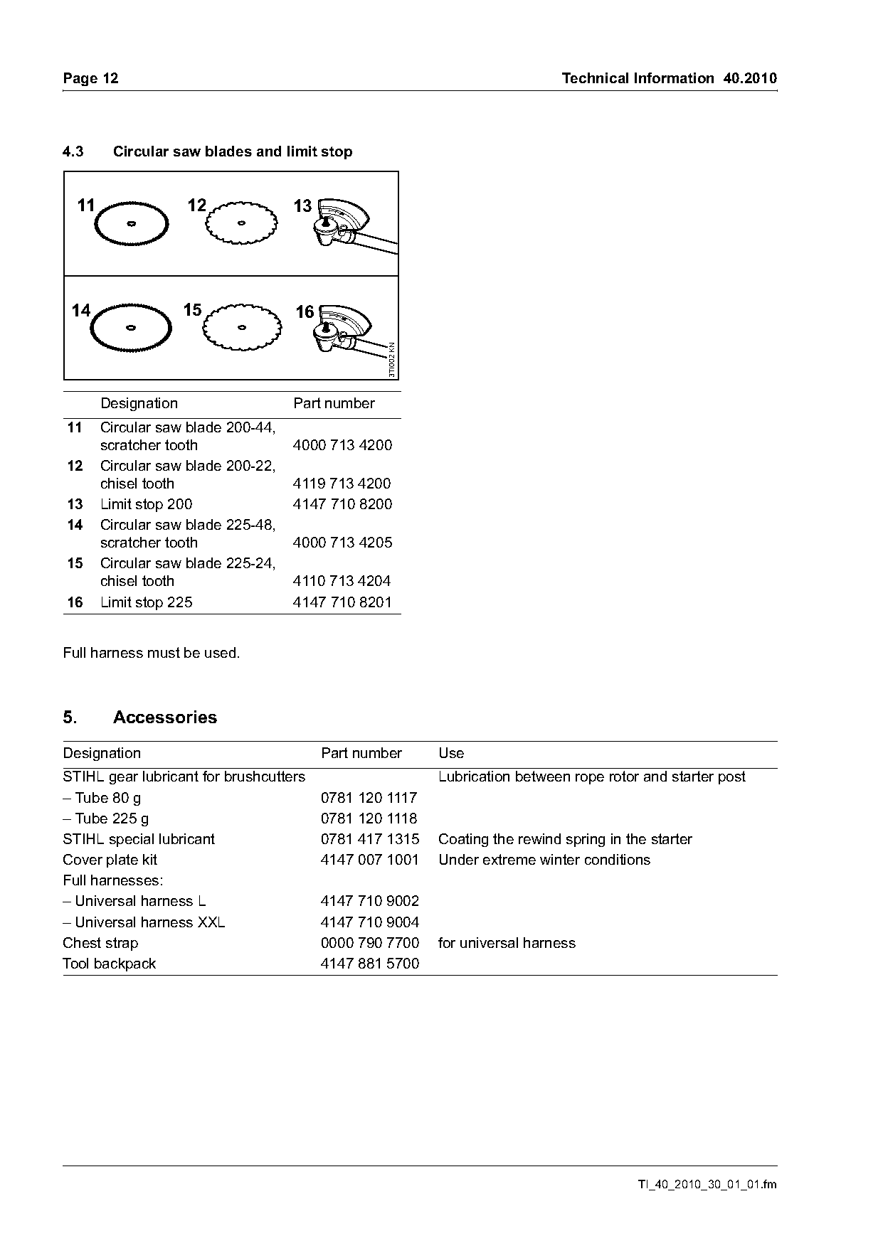
4.3     Circular saw blades and limit stop

  11                 12             13

 14                  15             16

                                                  3TI002 KN
       Designation                  Part number
11     Circular saw blade 200-44,
       scratcher tooth              4000 713 4200
12     Circular saw blade 200-22,
       chisel tooth                 4119 713 4200
13     Limit stop 200               4147 710 8200
14     Circular saw blade 225-48,
       scratcher tooth              4000 713 4205
15     Circular saw blade 225-24,
       chisel tooth                 4110 713 4204
16     Limit stop 225               4147 710 8201

Full harness must be used.

5.      Accessories
Designation                              Part number          Use
STIHL gear lubricant for brushcutters                         Lubrication between rope rotor and starter post
– Tube 80 g                              0781 120 1117
– Tube 225 g                             0781 120 1118
STIHL special lubricant                  0781 417 1315        Coating the rewind spring in the starter
Cover plate kit                          4147 007 1001        Under extreme winter conditions
Full harnesses:
– Universal harness L                    4147 710 9002
– Universal harness XXL                  4147 710 9004
Chest strap                              0000 790 7700        for universal harness
Tool backpack                            4147 881 5700

                                                                                             TI_40_2010_30_01_01.fm
Page 13 of 28
Text of page 13 — search, copy, screen readers
Technical Information 40.2010                                                                        Page 13

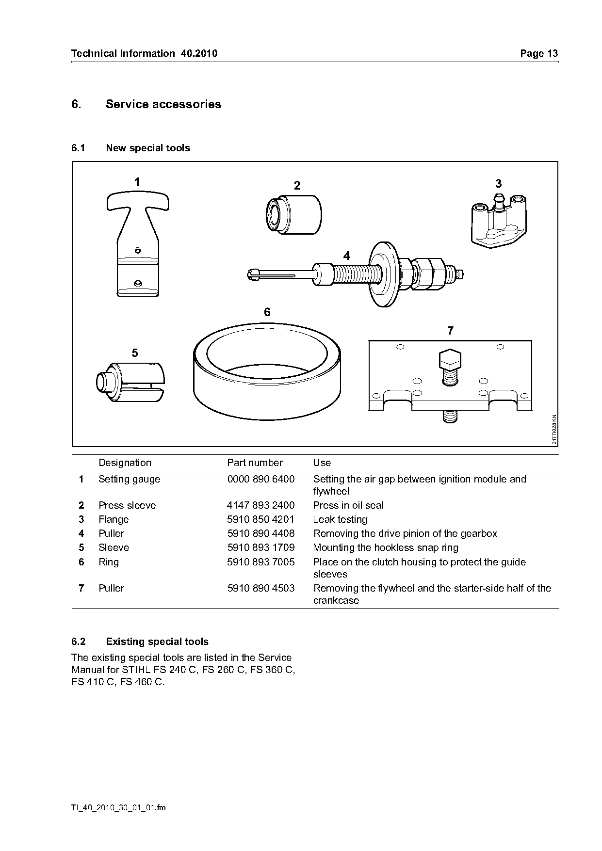
6.     Service accessories

6.1     New special tools

               1                                   2                                            3


                                            6
                                                                                     7
               5

                                                                                                                317TI028 KN
      Designation                   Part number        Use
 1    Setting gauge                 0000 890 6400      Setting the air gap between ignition module and
                                                       flywheel
 2    Press sleeve                  4147 893 2400      Press in oil seal
 3    Flange                        5910 850 4201      Leak testing
 4    Puller                        5910 890 4408      Removing the drive pinion of the gearbox
 5    Sleeve                        5910 893 1709      Mounting the hookless snap ring
 6    Ring                          5910 893 7005      Place on the clutch housing to protect the guide
                                                       sleeves
 7    Puller                        5910 890 4503      Removing the flywheel and the starter-side half of the
                                                       crankcase

6.2     Existing special tools
The existing special tools are listed in the Service
Manual for STIHL FS 240 C, FS 260 C, FS 360 C,
FS 410 C, FS 460 C.

TI_40_2010_30_01_01.fm
Page 14 of 28
Text of page 14 — search, copy, screen readers
Page 14                                                               Technical Information 40.2010

6.3     Aids

Designation                                   Part number     Use
Set of gaskets                                4147 007 1600   Engine
Set of carburetor parts                       4147 007 1700   Carburetor
Grease (225 g tube)                           0781 120 1111   Lubricating oil seals, sliding and bearing
                                                              points
Press fluid OH 723                            0781 957 9000
STIHL gear lubricant for brushcutters                         Lubricating the gearbox and lubrication
                                                              between the rope rotor and starter post
– Tube 80 g                                   0781 120 1117
– Tube 225 g                                  0781 120 1118
STIHL multi-purpose grease                                    Lubricating the drive shaft
– Tube 80 g                                   0781 120 1109
– Tube 225 g                                  0781 120 1110
Tube of sealant Dirko HT red                  0783 830 2000   Sealing the crankcase
Standard solvent-based degreasant not                         Cleaning mating surfaces and
containing any chlorinated or                                 carburetor, cleaning the crankshaft stub
halogenated hydrocarbons                                      and the cone in the flywheel

7.      Spare parts
The spare parts lists will be available in time for the
market launch and are already contained on the
03/2010 edition of the STIHL Service
Communication System DVD.

8.      Servicing
The specific national safety regulations and the
safety instructions in the instruction manual must be
observed if the machine has to be started up during
servicing.

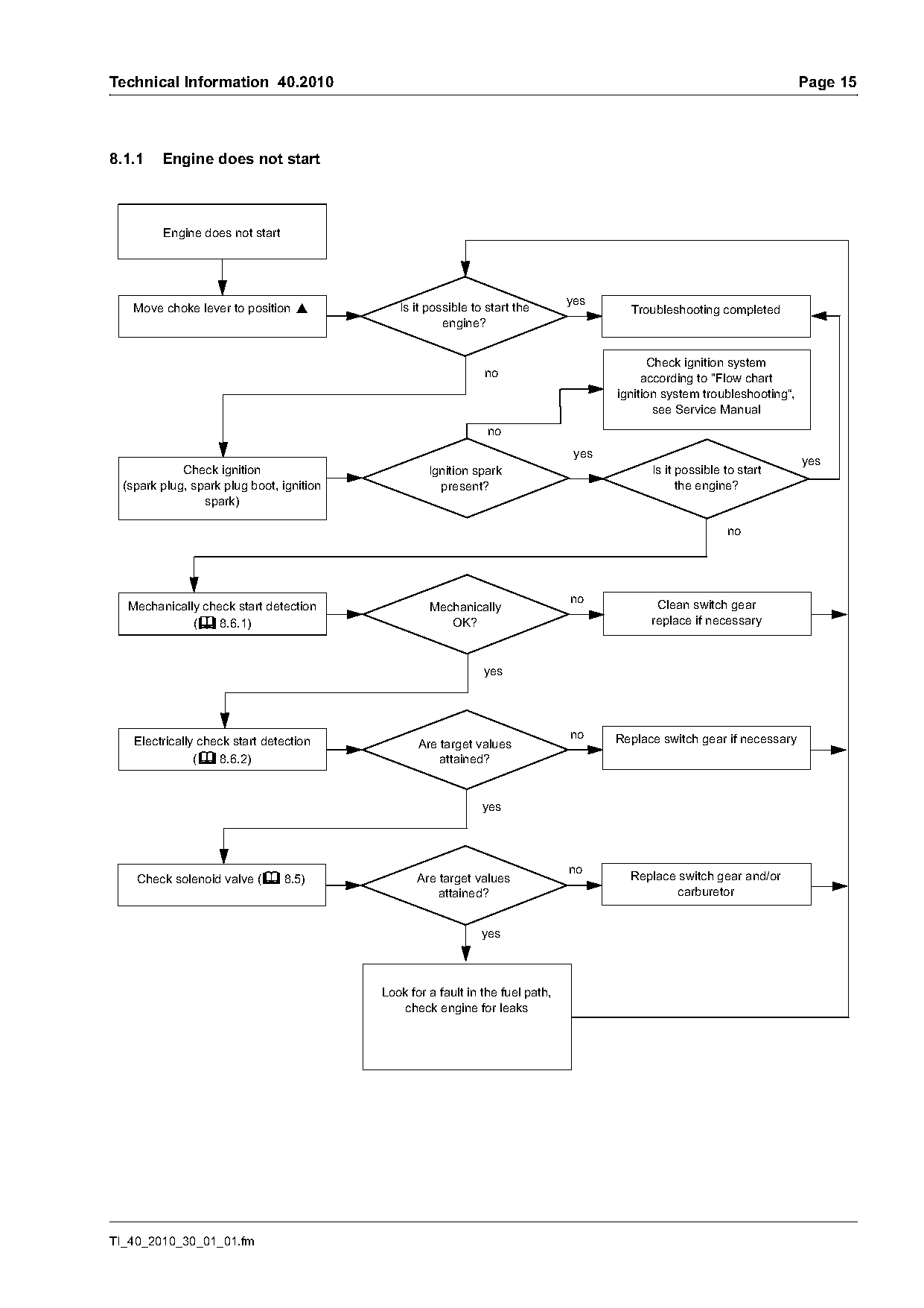
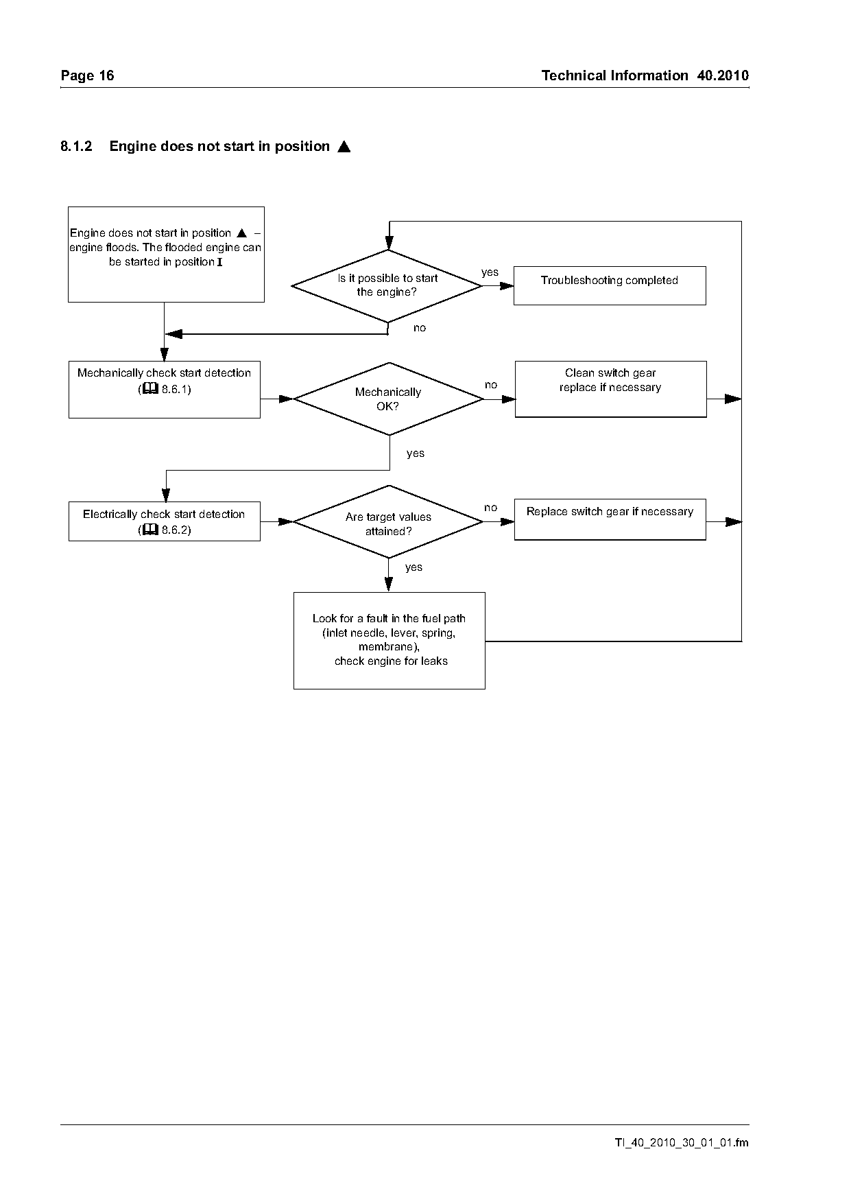
8.1     Troubleshooting plan
The flow charts that follow deal with specific parts
diagnosis and troubleshooting for the M-Tronic
engine management system.
The flow charts help you to take the correct step at
the correct time.

                                                                                  TI_40_2010_30_01_01.fm
Page 15 of 28
Text of page 15 — search, copy, screen readers
Technical Information 40.2010                                                                                              Page 15

8.1.1    Engine does not start

         Engine does not start

                                                                                yes
    Move choke lever to position }            Is it possible to start the                Troubleshooting completed
                                                       engine?

                                                                                             Check ignition system
                                                               no                           according to "Flow chart
                                                                                       ignition system troubleshooting“,
                                                                                              see Service Manual
                                                                                 yes
                                                                                                                           yes
             Check ignition                         Ignition spark                           Is it possible to start
  (spark plug, spark plug boot, ignition              present?                                     the engine?
                 spark)

  Mechanically check start detection                Mechanically                              Clean switch gear
             (b 8.6.1)                                 OK?                                   replace if necessary

                                                               yes

                                                                                no     Replace switch gear if necessary
    Electrically check start detection            Are target values
                (b 8.6.2)                             attained?

                                                               yes

    Check solenoid valve (b 8.5)                  Are target values                      Replace switch gear and/or
                                                      attained?                                 carburetor

                                                               yes

                                           Look for a fault in the fuel path,
                                              check engine for leaks

TI_40_2010_30_01_01.fm
Page 16 of 28
Text of page 16 — search, copy, screen readers
Page 16                                                                              Technical Information 40.2010

8.1.2   Engine does not start in position }

 Engine does not start in position } –
 engine floods. The flooded engine can
         be started in position F
                                                                             yes
                                              Is it possible to start                Troubleshooting completed
                                                    the engine?

  Mechanically check start detection                                                      Clean switch gear
             (b 8.6.1)                                                       no          replace if necessary
                                                  Mechanically
                                                     OK?

                                                             yes

                                                                             no    Replace switch gear if necessary
   Electrically check start detection           Are target values
               (b 8.6.2)                            attained?

                                                             yes

                                         Look for a fault in the fuel path
                                           (inlet needle, lever, spring,
                                                   membrane),
                                              check engine for leaks

                                                                                                   TI_40_2010_30_01_01.fm
Page 17 of 28
Text of page 17 — search, copy, screen readers
Technical Information 40.2010                                                                                        Page 17

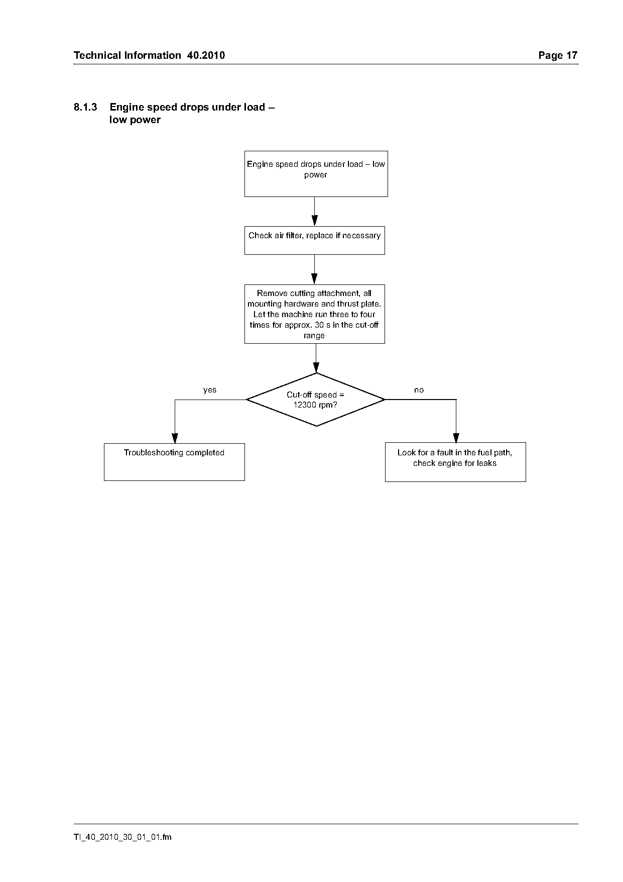
8.1.3   Engine speed drops under load –
        low power

                                       Engine speed drops under load – low
                                                     power

                                       Check air filter, replace if necessary

                                          Remove cutting attachment, all
                                       mounting hardware and thrust plate.
                                         Let the machine run three to four
                                       times for approx. 30 s in the cut-off
                                                      range

                              yes                                                   no
                                                 Cut-off speed =
                                                  12300 rpm?

           Troubleshooting completed                                            Look for a fault in the fuel path,
                                                                                   check engine for leaks

TI_40_2010_30_01_01.fm
Page 18 of 28
Text of page 18 — search, copy, screen readers
Page 18                                                                          Technical Information 40.2010

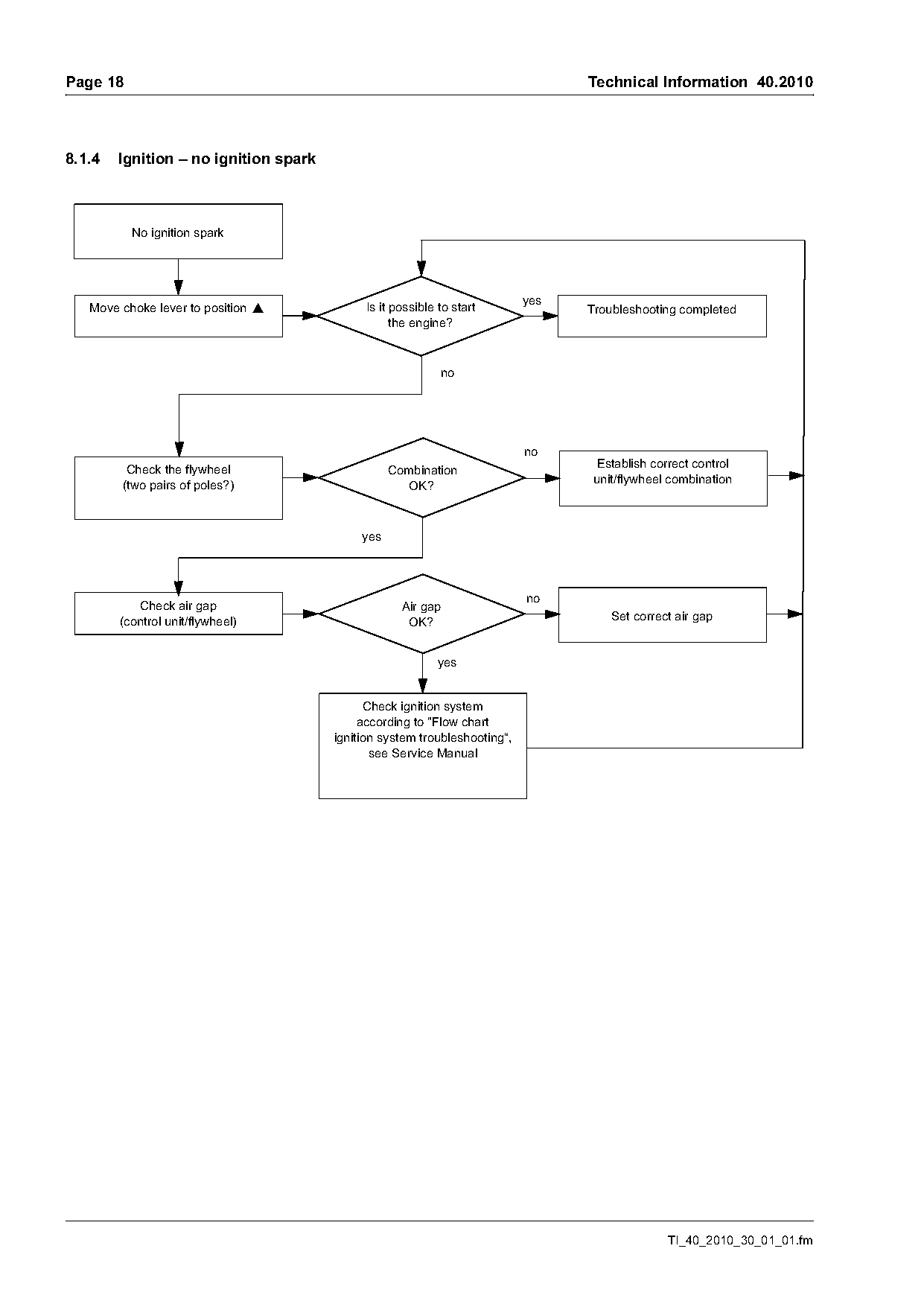
8.1.4   Ignition – no ignition spark

          No ignition spark

                                                                           yes
   Move choke lever to position }           Is it possible to start              Troubleshooting completed
                                                  the engine?

         Check the flywheel                                                       Establish correct control
                                                  Combination
        (two pairs of poles?)                                                     unit/flywheel combination
                                                    OK?

                                            yes

           Check air gap                            Air gap
        (control unit/flywheel)                      OK?                             Set correct air gap

                                                           yes

                                             Check ignition system
                                            according to "Flow chart
                                       ignition system troubleshooting“,
                                              see Service Manual

                                                                                               TI_40_2010_30_01_01.fm
Page 19 of 28
Text of page 19 — search, copy, screen readers
Technical Information 40.2010                                                                                Page 19

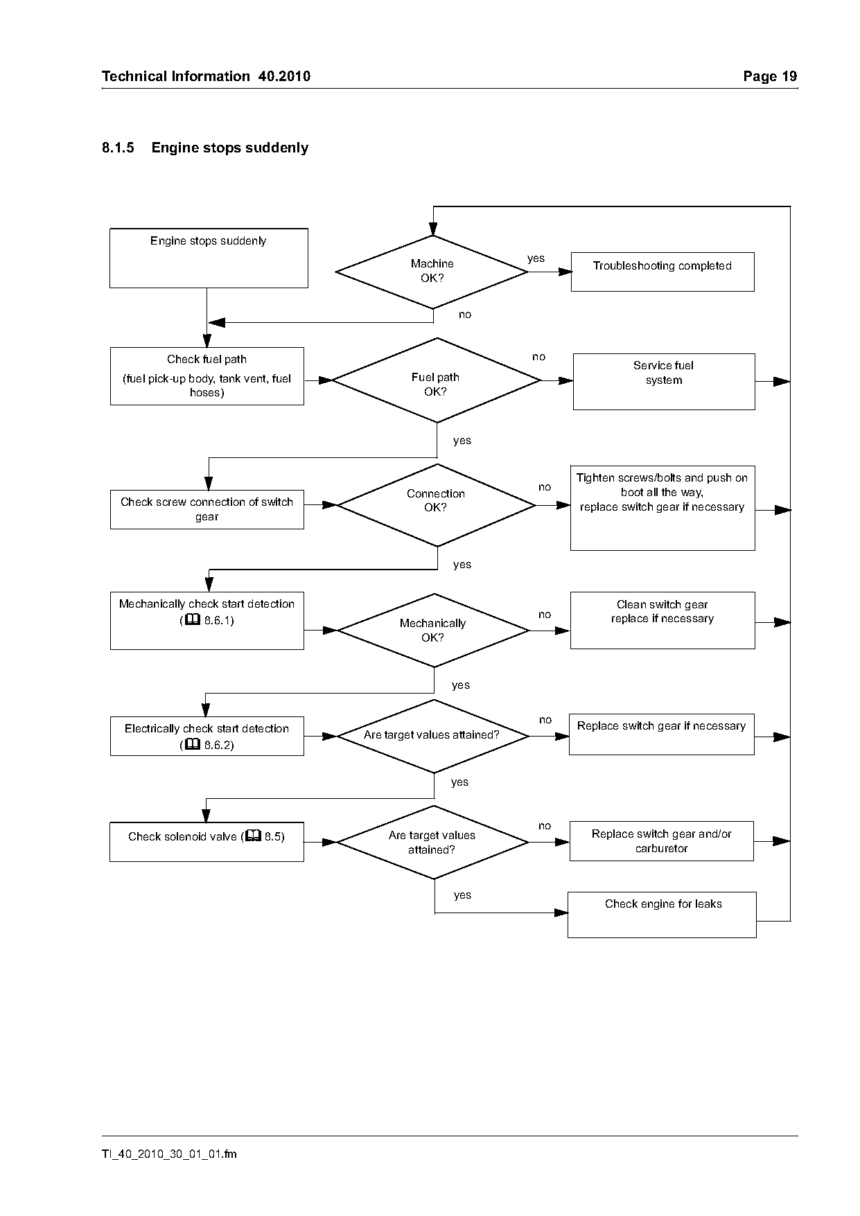
8.1.5   Engine stops suddenly

        Engine stops suddenly
                                                                       yes
                                                  Machine                       Troubleshooting completed
                                                   OK?

            Check fuel path                                            no
                                                                                       Service fuel
   (fuel pick-up body, tank vent, fuel            Fuel path                              system
                 hoses)                             OK?

                                                          yes

                                                                             Tighten screws/bolts and push on
                                                                        no            boot all the way,
                                                 Connection
  Check screw connection of switch                 OK?                        replace switch gear if necessary
               gear

                                                          yes

  Mechanically check start detection                                                Clean switch gear
             (b 8.6.1)                          Mechanically                       replace if necessary
                                                   OK?

                                                          yes

   Electrically check start detection                                        Replace switch gear if necessary
                                         Are target values attained?
               (b 8.6.2)

                                                          yes

    Check solenoid valve (b 8.5)             Are target values                 Replace switch gear and/or
                                                 attained?                            carburetor

                                                          yes
                                                                                  Check engine for leaks

TI_40_2010_30_01_01.fm
Page 20 of 28
Text of page 20 — search, copy, screen readers
Page 20                                                                                 Technical Information 40.2010

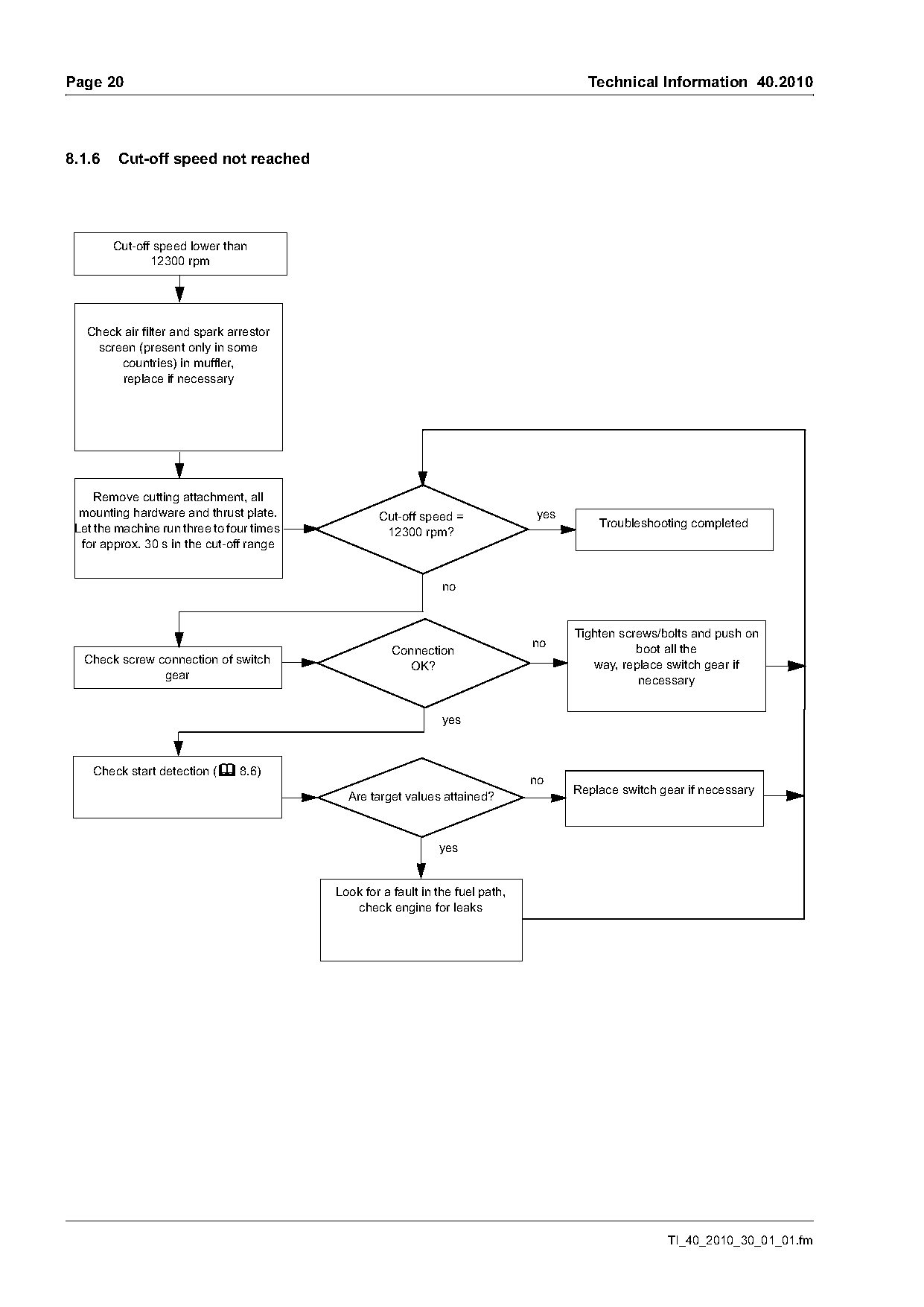
8.1.6    Cut-off speed not reached

        Cut-off speed lower than
               12300 rpm

   Check air filter and spark arrestor
    screen (present only in some
        countries) in muffler,
        replace if necessary

     Remove cutting attachment, all
  mounting hardware and thrust plate.              Cut-off speed =              yes
 Let the machine run three to four times                                                  Troubleshooting completed
                                                    12300 rpm?
  for approx. 30 s in the cut-off range

                                                                                      Tighten screws/bolts and push on
                                                                                no               boot all the
                                                      Connection
  Check screw connection of switch                      OK?                              way, replace switch gear if
               gear                                                                              necessary

                                                                yes

    Check start detection (b 8.6)
                                                                                      Replace switch gear if necessary
                                             Are target values attained?

                                                               yes

                                           Look for a fault in the fuel path,
                                              check engine for leaks

                                                                                                      TI_40_2010_30_01_01.fm
Page 21 of 28
Text of page 21 — search, copy, screen readers
Technical Information 40.2010                                                                                      Page 21

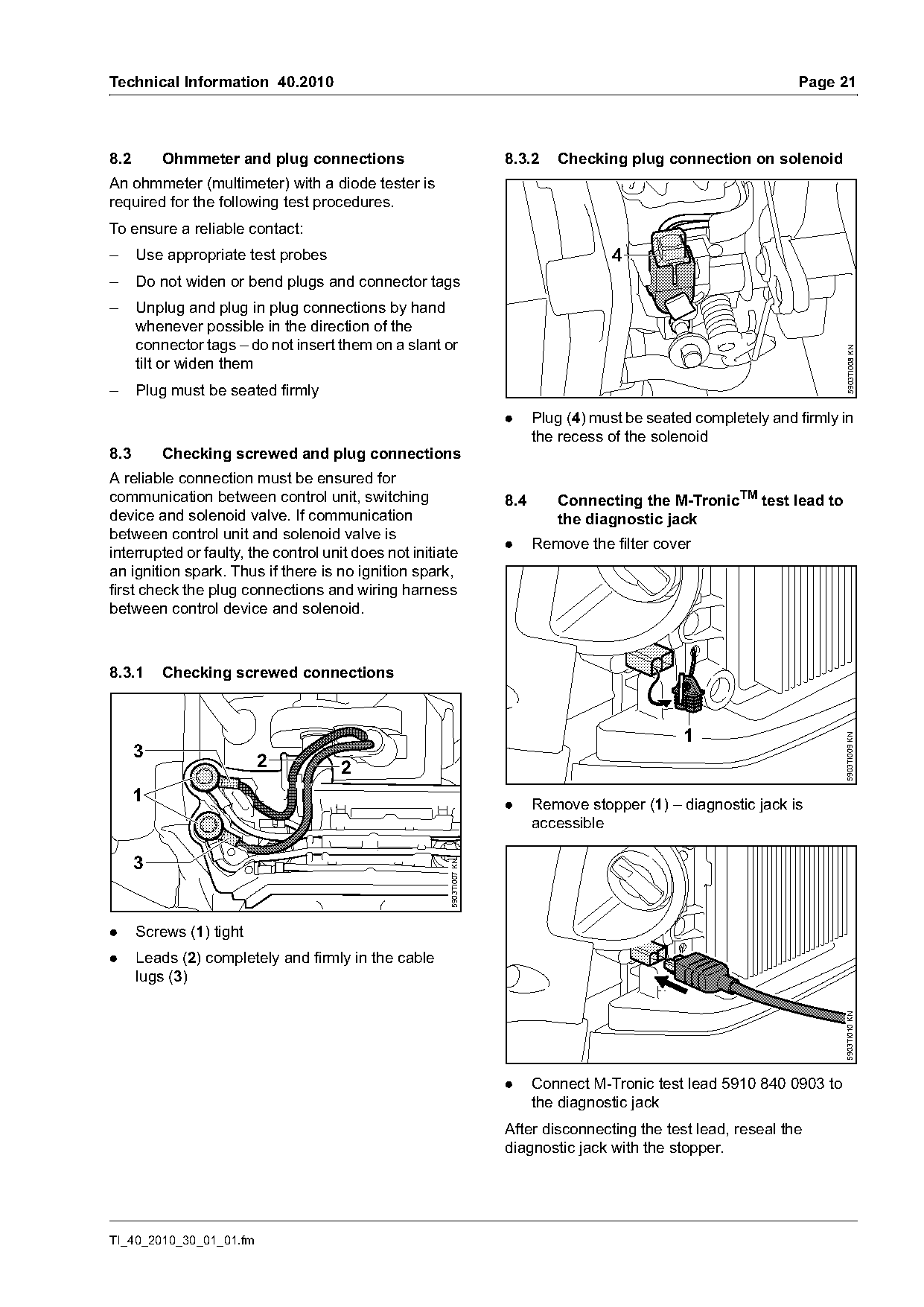
8.2       Ohmmeter and plug connections                               8.3.2    Checking plug connection on solenoid
An ohmmeter (multimeter) with a diode tester is
required for the following test procedures.
To ensure a reliable contact:
–     Use appropriate test probes                                                      4
–     Do not widen or bend plugs and connector tags
–     Unplug and plug in plug connections by hand
      whenever possible in the direction of the
      connector tags – do not insert them on a slant or

                                                                                                                          5903TI008 KN
      tilt or widen them
–     Plug must be seated firmly
                                                                      .     Plug (4) must be seated completely and firmly in
                                                                            the recess of the solenoid
8.3       Checking screwed and plug connections
A reliable connection must be ensured for
communication between control unit, switching                         8.4      Connecting the M-TronicTM test lead to
device and solenoid valve. If communication                                    the diagnostic jack
between control unit and solenoid valve is
                                                                      .     Remove the filter cover
interrupted or faulty, the control unit does not initiate
an ignition spark. Thus if there is no ignition spark,
first check the plug connections and wiring harness
between control device and solenoid.

8.3.1     Checking screwed connections


                                                                                                                          5903TI009 KN
      3                  2           2
      1                                                               .     Remove stopper (1) – diagnostic jack is
                                                                            accessible

      3
                                                       5903TI007 KN

.     Screws (1) tight
.     Leads (2) completely and firmly in the cable
      lugs (3)
                                                                                                                          5903TI010 KN

                                                                      .     Connect M-Tronic test lead 5910 840 0903 to
                                                                            the diagnostic jack
                                                                      After disconnecting the test lead, reseal the
                                                                      diagnostic jack with the stopper.

TI_40_2010_30_01_01.fm
Page 22 of 28
Text of page 22 — search, copy, screen readers
Page 22                                                                       Technical Information 40.2010

8.5      Checking the solenoid valve                    8.6      Checking the start detection system
                                                        .     Remove the filter cover
8.5.1    Measure resistance
                                                        .     Remove starter
.     Move choke lever to position F
                                                        .     Remove shroud
.     Connect M-Tronic test lead 5910 840 0903 to
      the diagnostic jack, see b 8.4
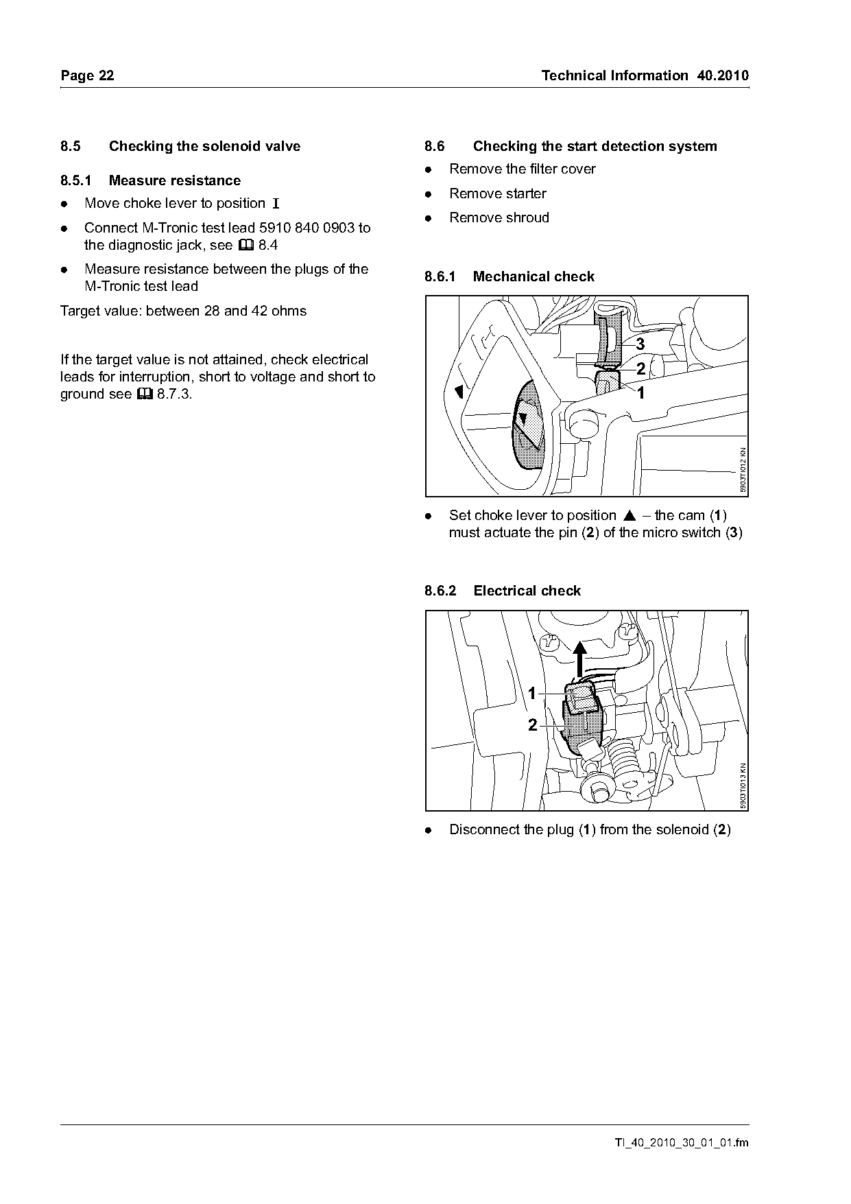
.     Measure resistance between the plugs of the       8.6.1    Mechanical check
      M-Tronic test lead
Target value: between 28 and 42 ohms

                                                                                            3
If the target value is not attained, check electrical
leads for interruption, short to voltage and short to                                       2
ground see b 8.7.3.                                                                         1

                                                                                                              5903TI012 KN
                                                        .     Set choke lever to position } – the cam (1)
                                                              must actuate the pin (2) of the micro switch (3)

                                                        8.6.2    Electrical check

                                                                          1
                                                                          2
                                                                                                              5903TI013 KN

                                                        .     Disconnect the plug (1) from the solenoid (2)

                                                                                         TI_40_2010_30_01_01.fm
Page 23 of 28
Text of page 23 — search, copy, screen readers
Technical Information 40.2010                                                                                     Page 23

                                                                     8.7      Checking the wiring harness

                         3           2
                                                                     8.7.1    Checking the ground connection
                                                                     .     Move choke lever to position F
    1
                                                                                                   2

                                                      5903TI014 KN
                                                                                             1
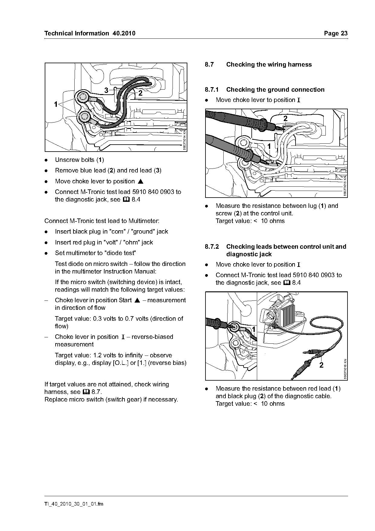
.   Unscrew bolts (1)
.   Remove blue lead (2) and red lead (3)

                                                                                                                         5903TI015 KN
.   Move choke lever to position }
.   Connect M-Tronic test lead 5910 840 0903 to
    the diagnostic jack, see b 8.4
                                                                     .     Measure the resistance between lug (1) and
                                                                           screw (2) at the control unit.
Connect M-Tronic test lead to Multimeter:                                  Target value: < 10 ohms
.   Insert black plug in "com" / "ground" jack
.   Insert red plug in "volt" / "ohm" jack
                                                                     8.7.2    Checking leads between control unit and
.   Set multimeter to "diode test"                                            diagnostic jack
    Test diode on micro switch – follow the direction                .     Move choke lever to position F
    in the multimeter Instruction Manual:
                                                                     .     Connect M-Tronic test lead 5910 840 0903 to
    If the micro switch (switching device) is intact,                      the diagnostic jack, see b 8.4
    readings will match the following target values:
–   Choke lever in position Start } – measurement
    in direction of flow
    Target value: 0.3 volts to 0.7 volts (direction of
    flow)
                                                                                       1
–   Choke lever in position F – reverse-biased
    measurement
    Target value: 1.2 volts to infinity – observe
                                                                                                                         5903TI016 KN

    display, e.g., display [O.L.] or [1.] (reverse bias)                                                      2

If target values are not attained, check wiring
                                                                     .     Measure the resistance between red lead (1)
harness, see b 8.7.
                                                                           and black plug (2) of the diagnostic cable.
Replace micro switch (switch gear) if necessary.
                                                                           Target value: < 10 ohms

TI_40_2010_30_01_01.fm
Page 24 of 28
Text of page 24 — search, copy, screen readers
Page 24                                                                                    Technical Information 40.2010

            3                                                           5

                                        4                                                                         6

                                                                                                                              5903TI019 KN
                                                    5903TI017 KN
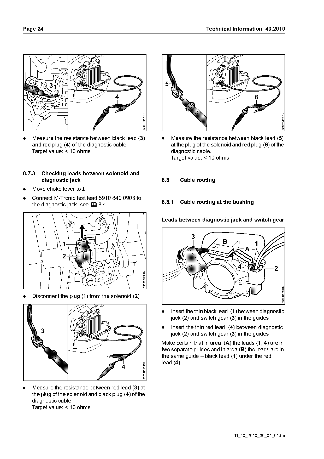
.   Measure the resistance between black lead (3)                   .       Measure the resistance between black lead (5)
    and red plug (4) of the diagnostic cable.                               at the plug of the solenoid and red plug (6) of the
    Target value: < 10 ohms                                                 diagnostic cable.
                                                                            Target value: < 10 ohms

8.7.3   Checking leads between solenoid and
        diagnostic jack                                             8.8         Cable routing
.   Move choke lever to F
.   Connect M-Tronic test lead 5910 840 0903 to
    the diagnostic jack, see b 8.4                                  8.8.1       Cable routing at the bushing

                                                                    Leads between diagnostic jack and switch gear

                                                                                     3
                 1                                                                                 B              1
                                                                                                              A
                 2
                                                                                                          4               2
                                                    5903TI013 KN

                                                                                                                              5903TI020 KN

.   Disconnect the plug (1) from the solenoid (2)

                                                                    .       Insert the thin black lead (1) between diagnostic
                                                                            jack (2) and switch gear (3) in the guides
                                                                    .       Insert the thin red lead (4) between diagnostic
        3                                                                   jack (2) and switch gear (3) in the guides
                                                                    Make certain that in area (A) the leads (1, 4) are in
                                                                    two separate guides and in area (B) the leads are in
                                                                    the same guide – black lead (1) under the red
                                                                    lead (4).
                                                     5903TI018 KN


.   Measure the resistance between red lead (3) at
    the plug of the solenoid and black plug (4) of the
    diagnostic cable.
    Target value: < 10 ohms

                                                                                                        TI_40_2010_30_01_01.fm
Page 25 of 28
Text of page 25 — search, copy, screen readers
Technical Information 40.2010                                                                                       Page 25

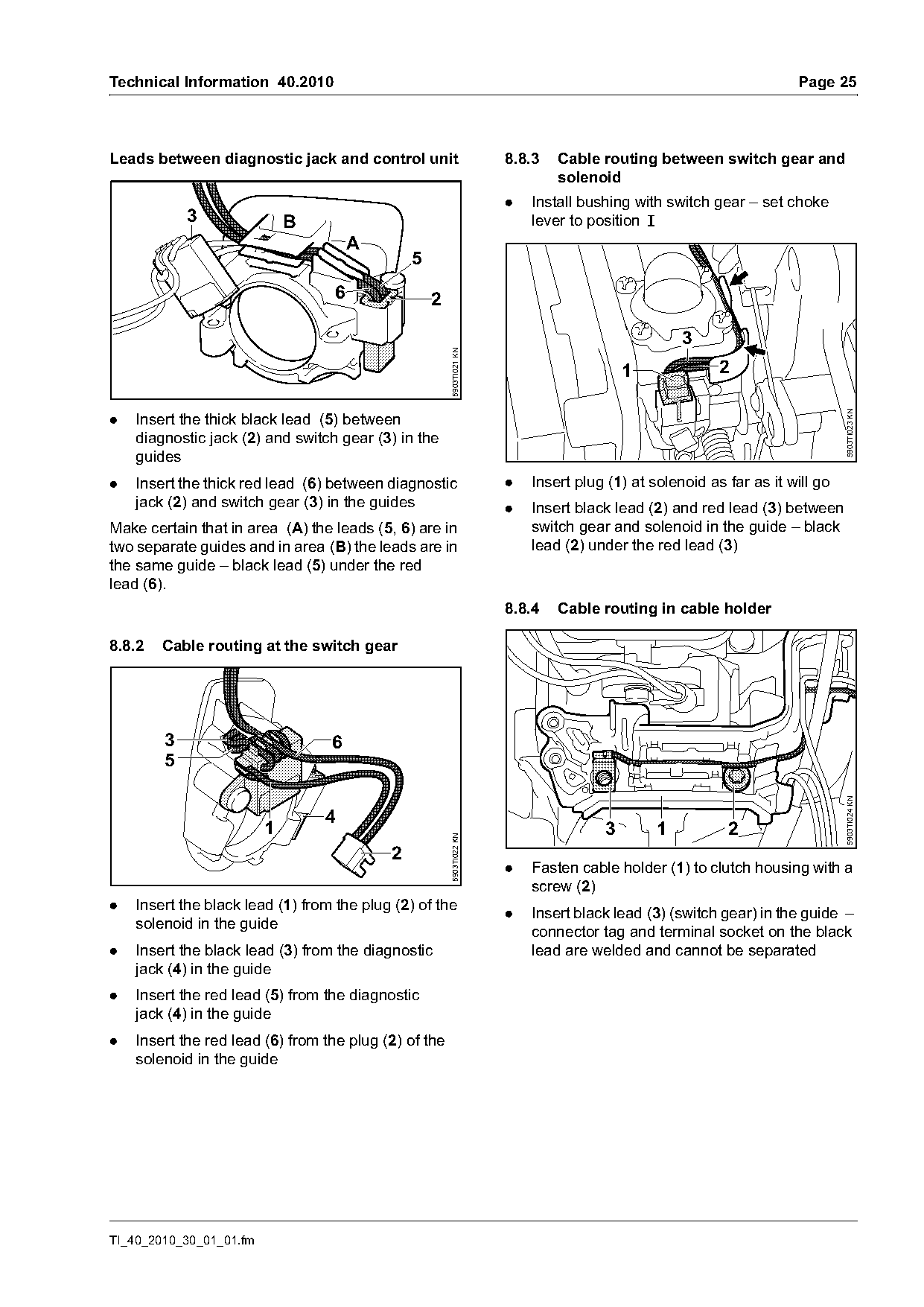
Leads between diagnostic jack and control unit                        8.8.3   Cable routing between switch gear and
                                                                              solenoid
                                                                      .   Install bushing with switch gear – set choke
            3                B                                            lever to position F
                                      A
                                               5
                                  6                2


                                                       5903TI021 KN
                                                                                         1              2

                                                                                                                             5903TI023 KN
.   Insert the thick black lead (5) between
    diagnostic jack (2) and switch gear (3) in the
    guides
.   Insert the thick red lead (6) between diagnostic                  .   Insert plug (1) at solenoid as far as it will go
    jack (2) and switch gear (3) in the guides                        .   Insert black lead (2) and red lead (3) between
Make certain that in area (A) the leads (5, 6) are in                     switch gear and solenoid in the guide – black
two separate guides and in area (B) the leads are in                      lead (2) under the red lead (3)
the same guide – black lead (5) under the red
lead (6).
                                                                      8.8.4   Cable routing in cable holder

8.8.2   Cable routing at the switch gear

        3                         6
        5

                                                                                                                             5903TI024 KN
                                 4
                         1                                                           3        1          2
                                                       5903TI022 KN

                                           2
                                                                      .   Fasten cable holder (1) to clutch housing with a
                                                                          screw (2)
.   Insert the black lead (1) from the plug (2) of the
                                                                      .   Insert black lead (3) (switch gear) in the guide –
    solenoid in the guide
                                                                          connector tag and terminal socket on the black
.   Insert the black lead (3) from the diagnostic                         lead are welded and cannot be separated
    jack (4) in the guide
.   Insert the red lead (5) from the diagnostic
    jack (4) in the guide
.   Insert the red lead (6) from the plug (2) of the
    solenoid in the guide

TI_40_2010_30_01_01.fm
Page 26 of 28
Text of page 26 — search, copy, screen readers
Page 26                                                                                     Technical Information 40.2010

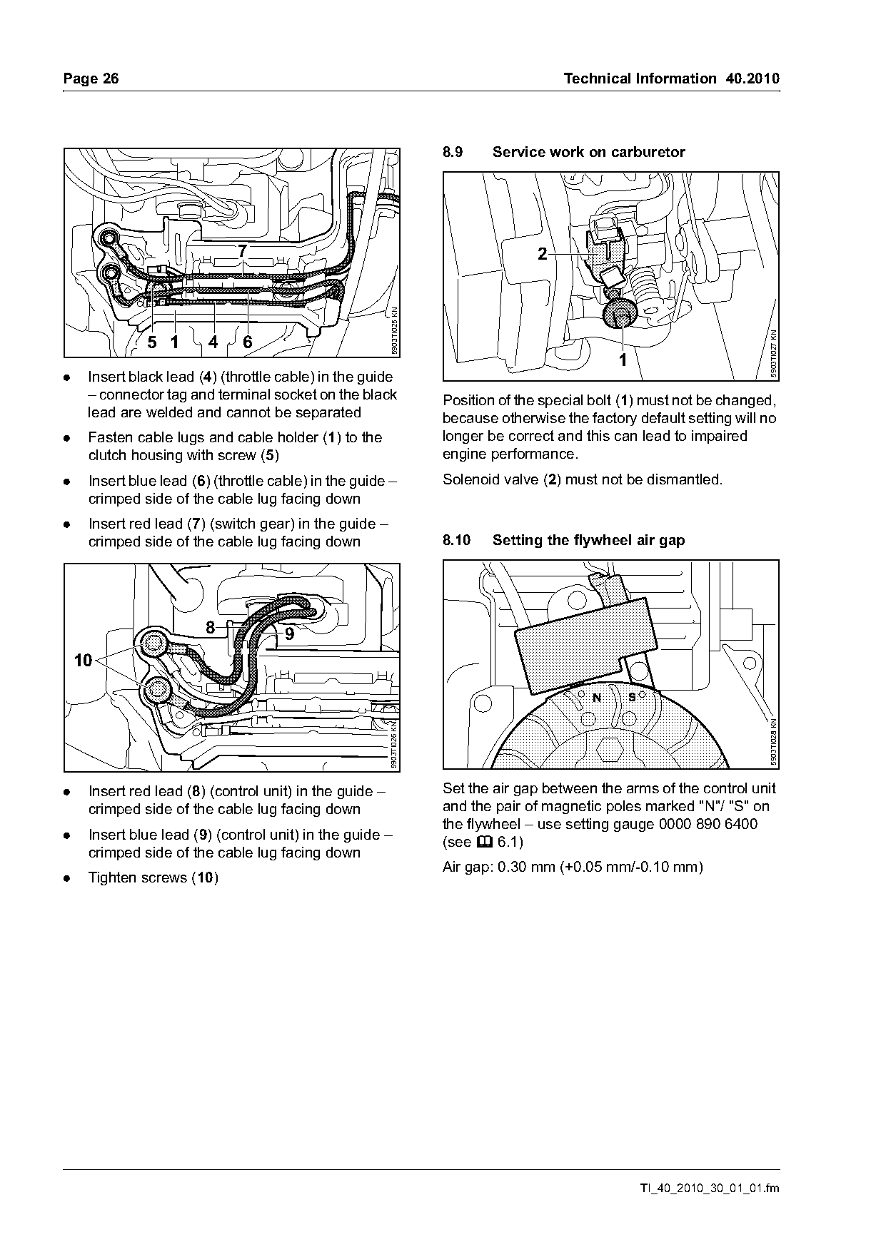
                                                                         8.9     Service work on carburetor

                              7                                                         2

                                                          5903TI025 KN

                                                                                                                            5903TI027 KN
              5 1        4     6
                                                                                                    1
.    Insert black lead (4) (throttle cable) in the guide
     – connector tag and terminal socket on the black                    Position of the special bolt (1) must not be changed,
     lead are welded and cannot be separated                             because otherwise the factory default setting will no
.    Fasten cable lugs and cable holder (1) to the                       longer be correct and this can lead to impaired
     clutch housing with screw (5)                                       engine performance.
.    Insert blue lead (6) (throttle cable) in the guide –                Solenoid valve (2) must not be dismantled.
     crimped side of the cable lug facing down
.    Insert red lead (7) (switch gear) in the guide –
     crimped side of the cable lug facing down                           8.10    Setting the flywheel air gap

                        8             9
    10

                                                                                                                            5903TI028 KN
                                                         5903TI026 KN

.    Insert red lead (8) (control unit) in the guide –                   Set the air gap between the arms of the control unit
     crimped side of the cable lug facing down                           and the pair of magnetic poles marked "N"/ "S" on
                                                                         the flywheel – use setting gauge 0000 890 6400
.    Insert blue lead (9) (control unit) in the guide –
                                                                         (see b 6.1)
     crimped side of the cable lug facing down
                                                                         Air gap: 0.30 mm (+0.05 mm/-0.10 mm)
.    Tighten screws (10)

                                                                                                        TI_40_2010_30_01_01.fm
Page 27 of 28
Text of page 27 — search, copy, screen readers
Technical Information 40.2010                                                                                     Page 27

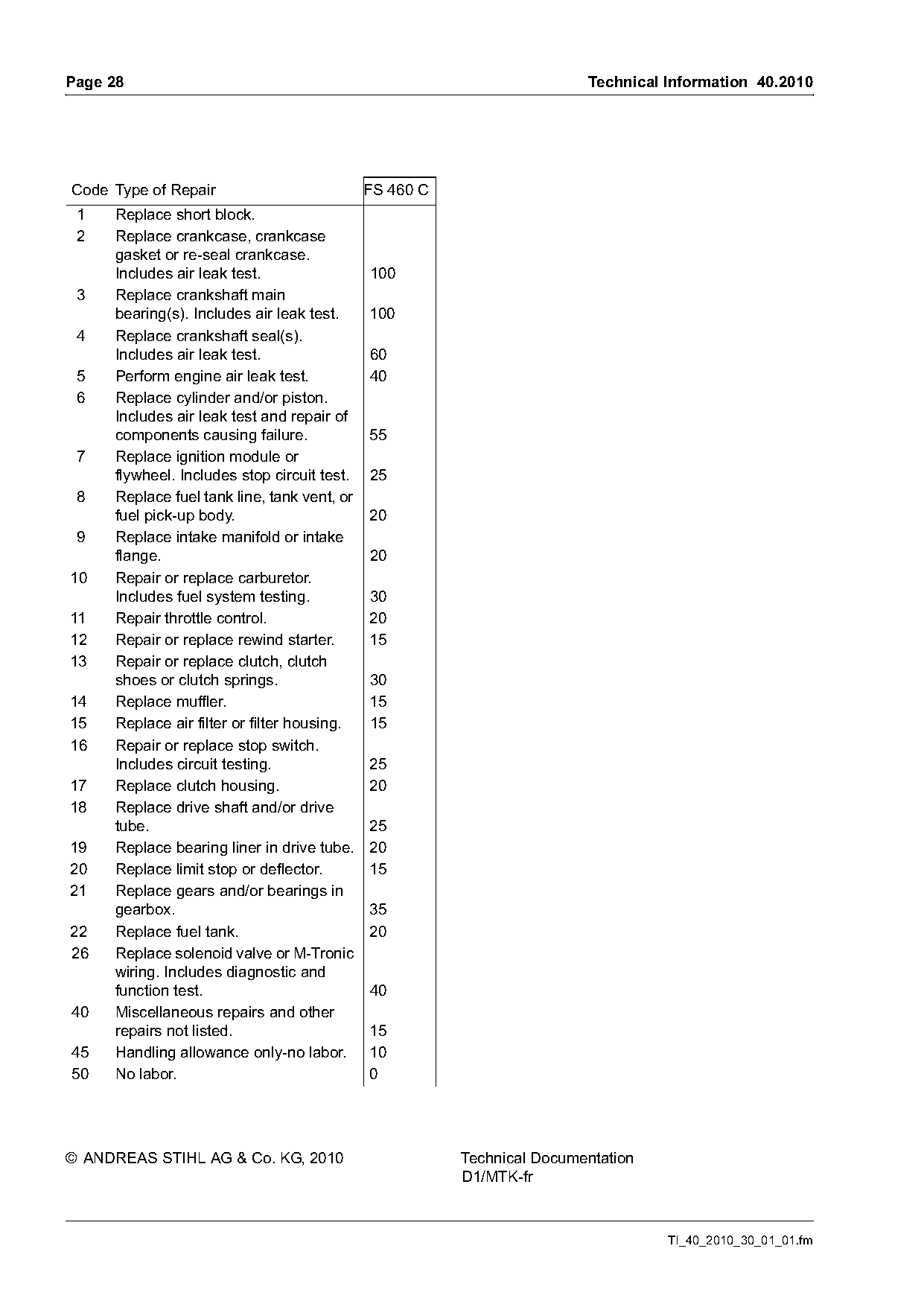
8.11    Calibrating the control unit                                 8.15   Repair times
If the control unit or carburetor is replaced during                 The specified repair times apply for trained and
servicing, the M-Tronic must be calibrated.                          qualified personnel as well as for properly equipped
                                                                     repair shops.
.   Remove cutting attachment, all mounting
    hardware and thrust plate                                        The repair times are specified in minutes.
.   Move choke lever to Start }
.   Start engine – do not blip the throttle trigger
.   Let the engine run for at least 90 seconds in the
    start position and then actuate the stop switch –
    calibration is completed
The control unit is adjusted to the carburetor while
the engine runs in the position Start }. The engine
must be switched off immediately for the information
to be stored in the control unit.

8.12    Tightening torques
The tightening torques are listed in the Service
Manual for STIHL FS 240 C, FS 260 C, FS 360 C,
FS 410 C, FS 460 C.

8.13    Service notes
Service and repair procedures are included in the
Service Manual STIHL FS 240 C, FS 260 C,
FS 360 C, FS 410 C, FS 460 C.

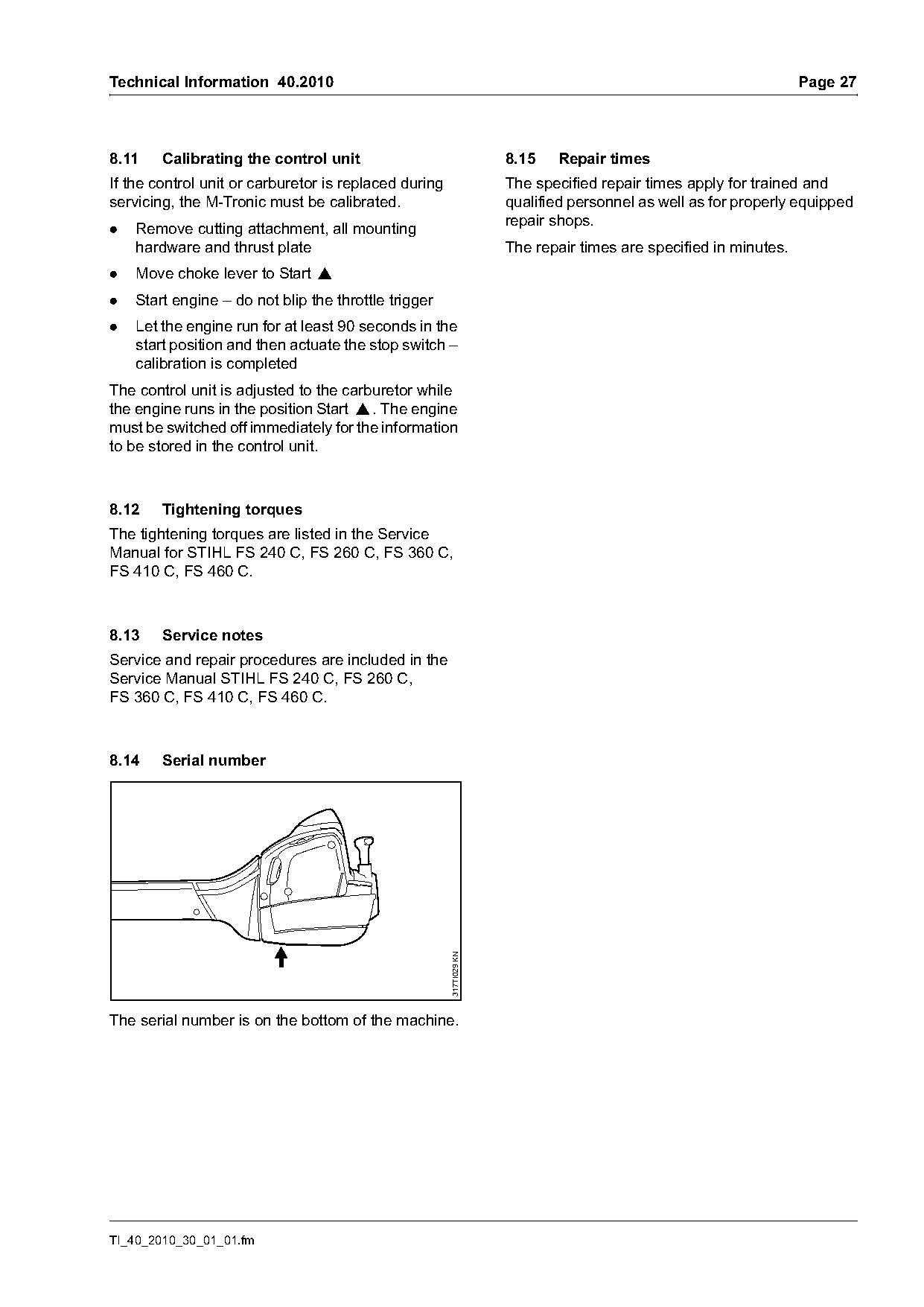
8.14    Serial number
                                                       317TI029 KN

The serial number is on the bottom of the machine.

TI_40_2010_30_01_01.fm
Page 28 of 28
Text of page 28 — search, copy, screen readers
Page 28                                                                 Technical Information 40.2010

Code Type of Repair                          FS 460 C
 1   Replace short block.
 2   Replace crankcase, crankcase
     gasket or re-seal crankcase.
     Includes air leak test.                 100
 3   Replace crankshaft main
     bearing(s). Includes air leak test.     100
 4   Replace crankshaft seal(s).
     Includes air leak test.                 60
 5   Perform engine air leak test.           40
 6   Replace cylinder and/or piston.
     Includes air leak test and repair of
     components causing failure.             55
 7   Replace ignition module or
     flywheel. Includes stop circuit test.   25
 8   Replace fuel tank line, tank vent, or
     fuel pick-up body.                      20
 9   Replace intake manifold or intake
     flange.                                 20
10   Repair or replace carburetor.
     Includes fuel system testing.           30
11   Repair throttle control.                20
12   Repair or replace rewind starter.       15
13   Repair or replace clutch, clutch
     shoes or clutch springs.                30
14   Replace muffler.                        15
15   Replace air filter or filter housing.   15
16   Repair or replace stop switch.
     Includes circuit testing.               25
17   Replace clutch housing.                 20
18   Replace drive shaft and/or drive
     tube.                                   25
19   Replace bearing liner in drive tube.    20
20   Replace limit stop or deflector.        15
21   Replace gears and/or bearings in
     gearbox.                                35
22   Replace fuel tank.                      20
26   Replace solenoid valve or M-Tronic
     wiring. Includes diagnostic and
     function test.                          40
40   Miscellaneous repairs and other
     repairs not listed.                     15
45   Handling allowance only-no labor.       10
50   No labor.                               0

© ANDREAS STIHL AG & Co. KG, 2010                       Technical Documentation
                                                        D1/MTK-fr

                                                                                  TI_40_2010_30_01_01.fm
Most of these PDFs embed fonts with a shifted character map, so the text above was recovered rather than copied — read it as a faithful but imperfect transcription, and treat the page image above each block as the authority where the two disagree — the figures exist only there, because they are vector drawings that text extraction cannot keep.