Technical Information · issue 51 of 2010
New analyzer STIHL ADG 2
IssueTI 51/2010
Full text
Page 1 of 21
Text of page 1 — search, copy, screen readers
STIH)

Technical Information                      51.2010

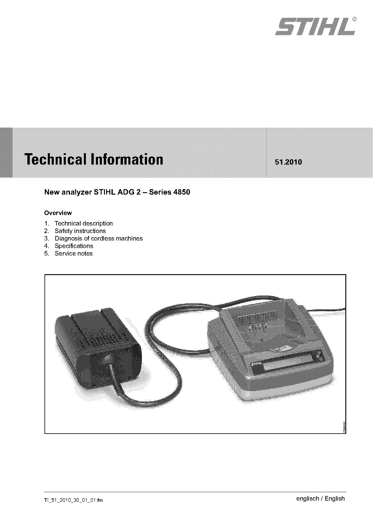
  New analyzer STIHL ADG 2 – Series 4850

  Overview
  1.   Technical description
  2.   Safety instructions
  3.   Diagnosis of cordless machines
  4.   Specifications
  5.   Service notes

  TI_51_2010_30_01_01.fm                        englisch / English
Page 2 of 21
Text of page 2 — search, copy, screen readers
Page 2                                                                                 Technical Information 51.2010

1.            Technical description                               Instruction Manual.

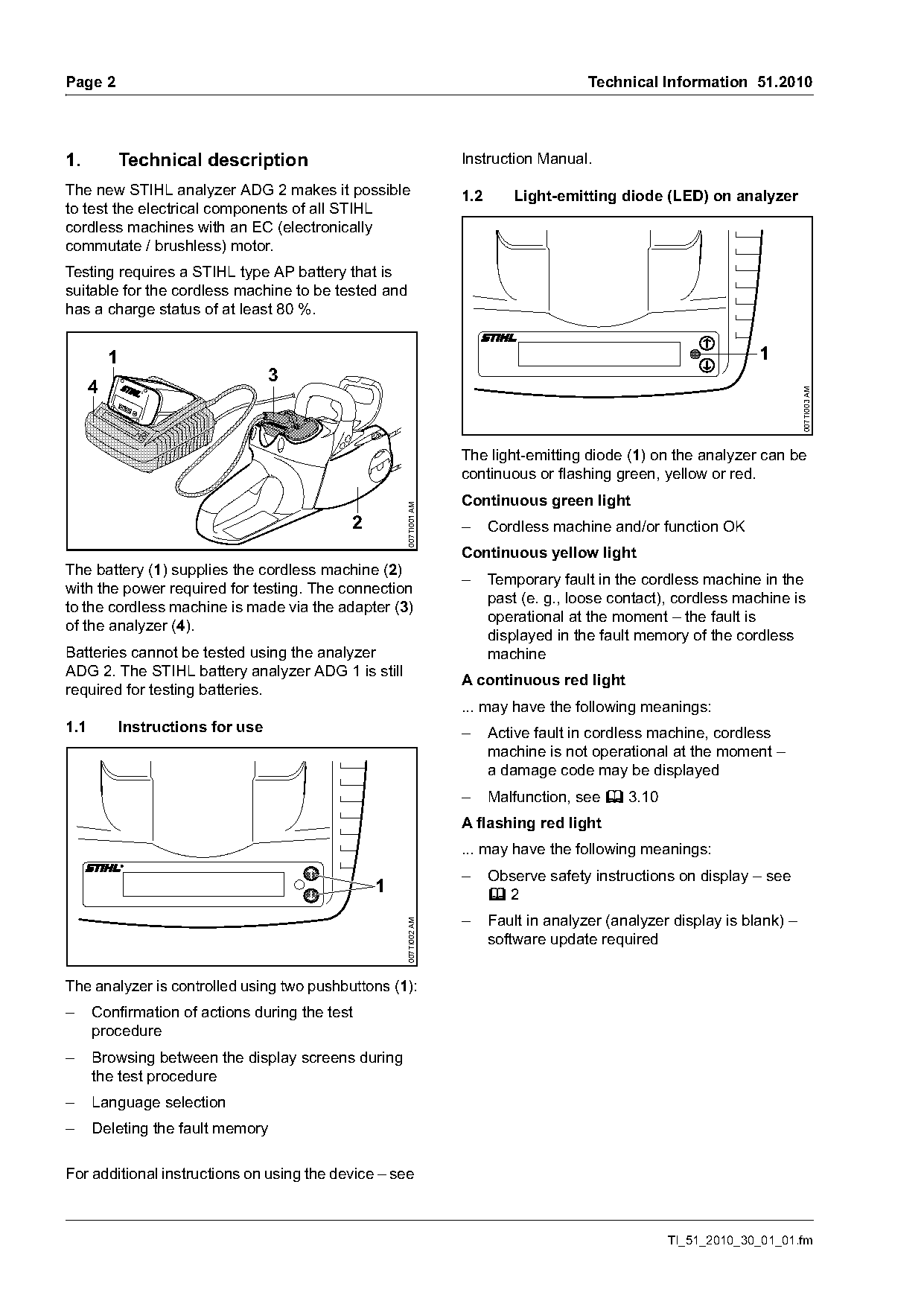
The new STIHL analyzer ADG 2 makes it possible                    1.2       Light-emitting diode (LED) on analyzer
to test the electrical components of all STIHL
cordless machines with an EC (electronically
commutate / brushless) motor.
Testing requires a STIHL type AP battery that is
suitable for the cordless machine to be tested and
has a charge status of at least 80 %.

          1                                                                                                      1
                                     3
      4

                                                                                                                          007TI003 AM
                                                                  The light-emitting diode (1) on the analyzer can be
                                                                  continuous or flashing green, yellow or red.
                                                                  Continuous green light
                                                    007TI001 AM

                                            2                     –     Cordless machine and/or function OK
                                                                  Continuous yellow light
The battery (1) supplies the cordless machine (2)
                                                                  –     Temporary fault in the cordless machine in the
with the power required for testing. The connection
                                                                        past (e. g., loose contact), cordless machine is
to the cordless machine is made via the adapter (3)
                                                                        operational at the moment – the fault is
of the analyzer (4).
                                                                        displayed in the fault memory of the cordless
Batteries cannot be tested using the analyzer                           machine
ADG 2. The STIHL battery analyzer ADG 1 is still
                                                                  A continuous red light
required for testing batteries.
                                                                  ... may have the following meanings:
1.1           Instructions for use                                –     Active fault in cordless machine, cordless
                                                                        machine is not operational at the moment –
                                                                        a damage code may be displayed
                                                                  –     Malfunction, see b 3.10
                                                                  A flashing red light
                                                                  ... may have the following meanings:
                                                                  –     Observe safety instructions on display – see
                                                1                       b2
                                                                  –     Fault in analyzer (analyzer display is blank) –
                                                    007TI002 AM

                                                                        software update required

The analyzer is controlled using two pushbuttons (1):
–     Confirmation of actions during the test
      procedure
–     Browsing between the display screens during
      the test procedure
–     Language selection
–     Deleting the fault memory

For additional instructions on using the device – see

                                                                                                   TI_51_2010_30_01_01.fm
Page 3 of 21
Text of page 3 — search, copy, screen readers
Technical Information 51.2010                                                                           Page 3

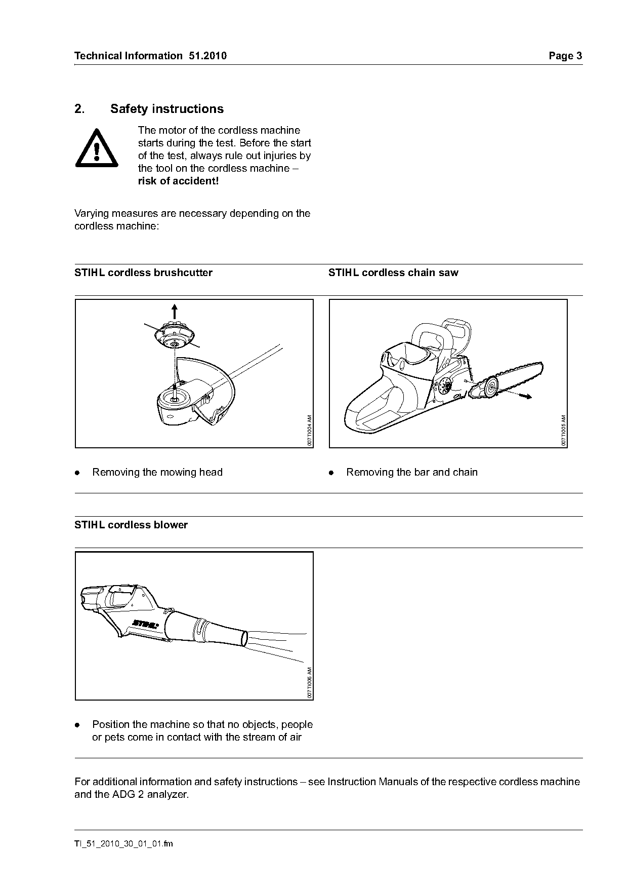
2.      Safety instructions
              The motor of the cordless machine
              starts during the test. Before the start
              of the test, always rule out injuries by
              the tool on the cordless machine –
              risk of accident!

Varying measures are necessary depending on the
cordless machine:

STIHL cordless brushcutter                                        STIHL cordless chain saw

                                                    007TI004 AM

                                                                                                          007TI005 AM
.    Removing the mowing head                                     .   Removing the bar and chain

STIHL cordless blower
                                                    007TI006 AM

.    Position the machine so that no objects, people
     or pets come in contact with the stream of air

For additional information and safety instructions – see Instruction Manuals of the respective cordless machine
and the ADG 2 analyzer.

TI_51_2010_30_01_01.fm
Page 4 of 21
Text of page 4 — search, copy, screen readers
Page 4                                                                            Technical Information 51.2010

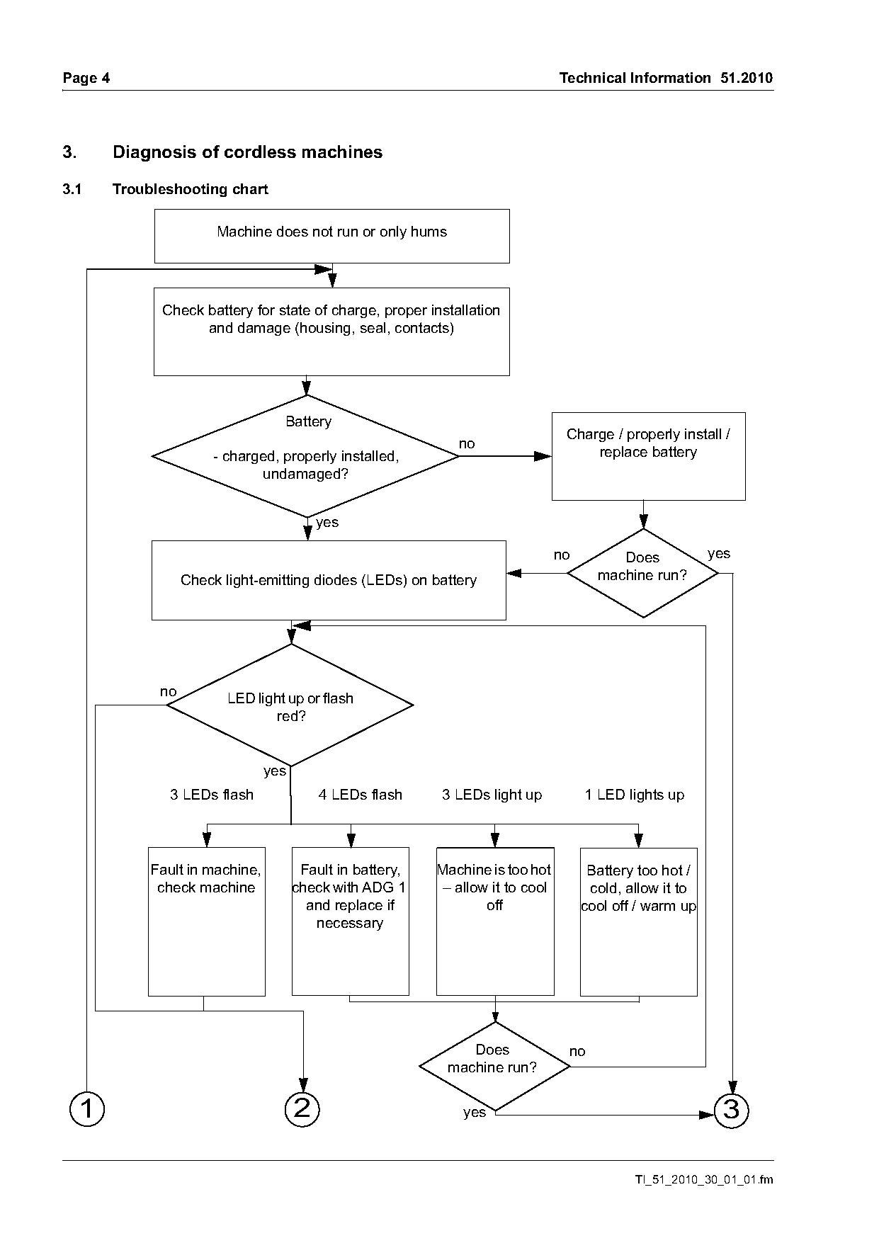
3.       Diagnosis of cordless machines

3.1      Troubleshooting chart

                         Machine does not run or only hums

               Check battery for state of charge, proper installation
                     and damage (housing, seal, contacts)

                                    Battery
                                                                                   Charge / properly install /
                        - charged, properly installed,                                 replace battery
                               undamaged?

                                            yes

                                                                                  no        Does            yes
                    Check light-emitting diodes (LEDs) on battery                        machine run?

               no          LED light up or flash
                                  red?

                                  yes
                 3 LEDs flash               4 LEDs flash     3 LEDs light up           1 LED lights up

              Fault in machine,          Fault in battery,   Machine is too hot         Battery too hot /
               check machine            check with ADG 1     – allow it to cool         cold, allow it to
                                          and replace if            off                cool off / warm up
                                           necessary

                                                                 Does              no
                                                              machine run?

     1                                  2                        yes                                         3

                                                                                               TI_51_2010_30_01_01.fm
Page 5 of 21
Text of page 5 — search, copy, screen readers
Technical Information 51.2010                                                             Page 5

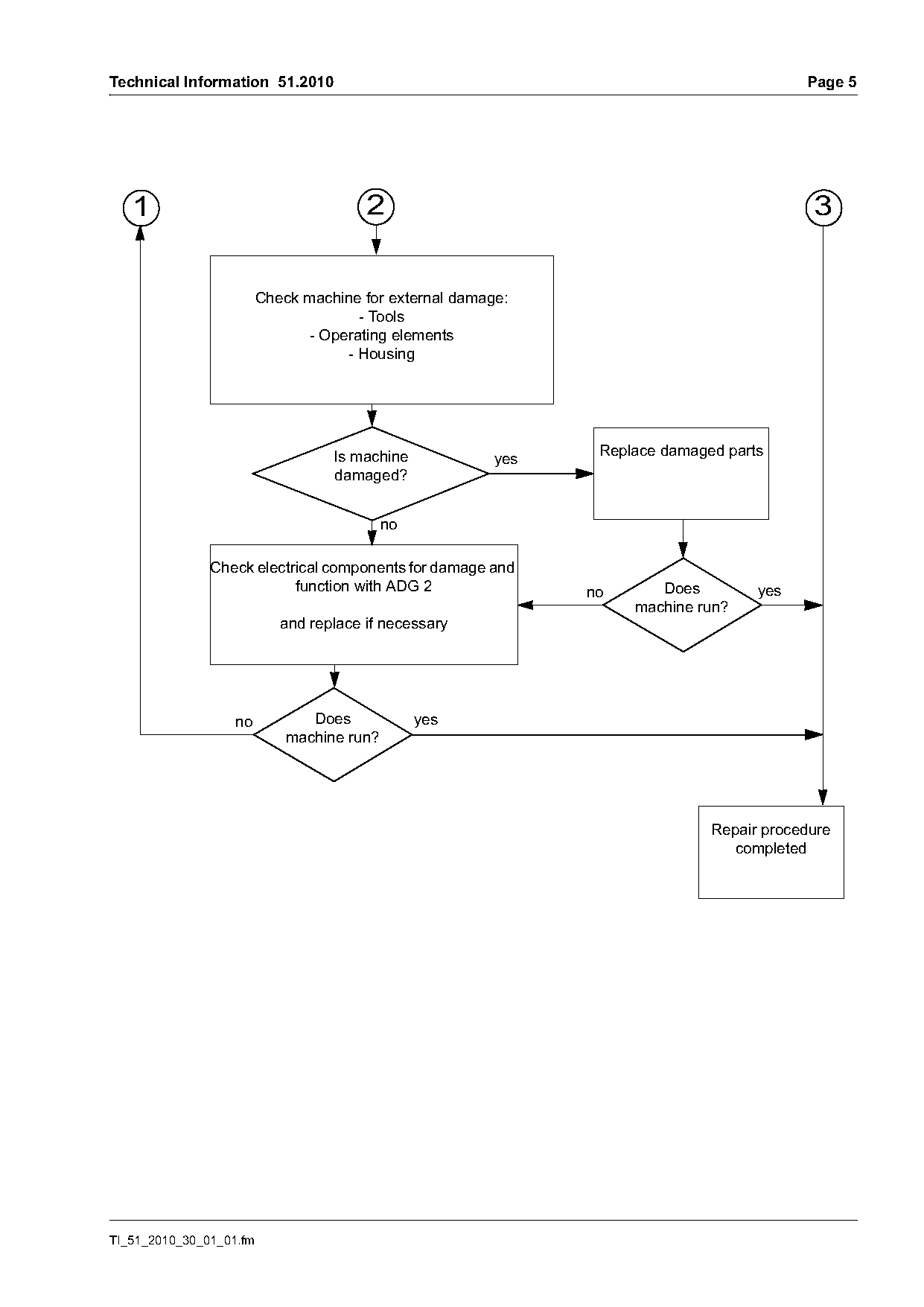
   1                                    2                                                  3

                         Check machine for external damage:
                                      - Tools
                               - Operating elements
                                    - Housing

                                   Is machine                   Replace damaged parts
                                                         yes
                                   damaged?

               Check electrical components for damage and
                           function with ADG 2                 no      Does         yes
                                                                    machine run?
                            and replace if necessary

                   no           Does             yes
                             machine run?

                                                                              Repair procedure
                                                                                completed

TI_51_2010_30_01_01.fm
Page 6 of 21
Text of page 6 — search, copy, screen readers
Page 6                                                                                      Technical Information 51.2010

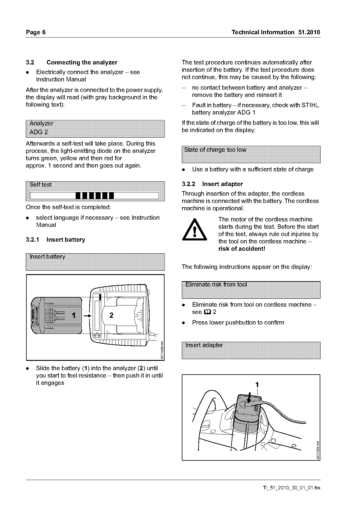
3.2       Connecting the analyzer                                     The test procedure continues automatically after
.     Electrically connect the analyzer – see                         insertion of the battery. If the test procedure does
      Instruction Manual                                              not continue, this may be caused by the following:

After the analyzer is connected to the power supply,                  –     no contact between battery and analyzer –
the display will read (with gray background in the                          remove the battery and reinsert it
following text):                                                      –     Fault in battery – if necessary, check with STIHL
                                                                            battery analyzer ADG 1
    Analyzer                                                          If the state of charge of the battery is too low, this will
    ADG 2                                                             be indicated on the display:

Afterwards a self-test will take place. During this
process, the light-emitting diode on the analyzer                      State of charge too low
turns green, yellow and then red for
approx. 1 second and then goes out again.
                                                                      .     Use a battery with a sufficient state of charge

    Self test                                                         3.2.2     Insert adapter
                                                                      Through insertion of the adapter, the cordless
                                                                      machine is connected with the battery. The cordless
Once the self-test is completed:                                      machine is operational.
.     select language if necessary – see Instruction                                  The motor of the cordless machine
      Manual                                                                          starts during the test. Before the start
                                                                                      of the test, always rule out injuries by
3.2.1     Insert battery                                                              the tool on the cordless machine –
                                                                                      risk of accident!
    Insert battery
                                                                      The following instructions appear on the display:

                                                                          Eliminate risk from tool

                                                                      .     Eliminate risk from tool on cordless machine –
                                                                            see b 2
                                    2
                                                                      .     Press lower pushbutton to confirm
                                                        007TI008 AM

                                                                          Insert adapter

.     Slide the battery (1) into the analyzer (2) until
      you start to feel resistance – then push it in until
      it engages                                                                                     1
                                                                                                                               007TI009 AM

                                                                                                         TI_51_2010_30_01_01.fm
Page 7 of 21
Text of page 7 — search, copy, screen readers
Technical Information 51.2010                                                                       Page 7

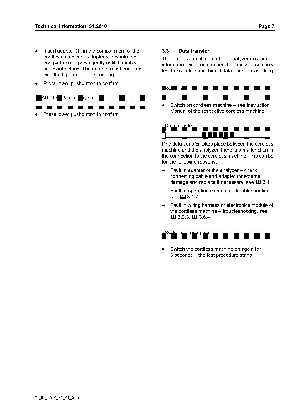
.     Insert adapter (1) in the compartment of the   3.3       Data transfer
      cordless machine – adapter slides into the     The cordless machine and the analyzer exchange
      compartment – press gently until it audibly    information with one another. The analyzer can only
      snaps into place. The adapter must end flush   test the cordless machine if data transfer is working.
      with the top edge of the housing
.     Press lower pushbutton to confirm
                                                         Switch on unit
    CAUTION! Motor may start
                                                     .     Switch on cordless machine – see Instruction
                                                           Manual of the respective cordless machine
.     Press lower pushbutton to confirm

                                                         Data transfer

                                                     If no data transfer takes place between the cordless
                                                     machine and the analyzer, there is a malfunction in
                                                     the connection to the cordless machine. This can be
                                                     for the following reasons:
                                                     –     Fault in adapter of the analyzer – check
                                                           connecting cable and adapter for external
                                                           damage and replace if necessary, see b 5.1
                                                     –     Fault in operating elements – troubleshooting,
                                                           see b 3.4.2
                                                     –     Fault in wiring harness or electronics module of
                                                           the cordless machine – troubleshooting, see
                                                           b 3.6.3, b 3.6.4

                                                         Switch unit on again

                                                     .     Switch the cordless machine on again for
                                                           3 seconds – the test procedure starts

TI_51_2010_30_01_01.fm
Page 8 of 21
Text of page 8 — search, copy, screen readers
Page 8                                                                  Technical Information 51.2010

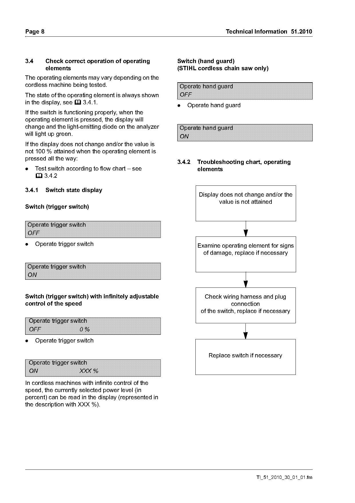
3.4       Check correct operation of operating        Switch (hand guard)
          elements                                    (STIHL cordless chain saw only)
The operating elements may vary depending on the
cordless machine being tested.                        Operate hand guard
The state of the operating element is always shown    OFF
in the display, see b 3.4.1.
                                                      .   Operate hand guard
If the switch is functioning properly, when the
operating element is pressed, the display will
change and the light-emitting diode on the analyzer   Operate hand guard
will light up green.                                  ON
If the display does not change and/or the value is
not 100 % attained when the operating element is
pressed all the way:
                                                      3.4.2   Troubleshooting chart, operating
.     Test switch according to flow chart – see               elements
      b 3.4.2

3.4.1     Switch state display
                                                              Display does not change and/or the
                                                                     value is not attained
Switch (trigger switch)

Operate trigger switch
OFF
.     Operate trigger switch                                  Examine operating element for signs
                                                                of damage, replace if necessary

Operate trigger switch

Switch (trigger switch) with infinitely adjustable              Check wiring harness and plug
control of the speed                                                       connection
                                                               of the switch, replace if necessary
    Operate trigger switch
    OFF                0%
.     Operate trigger switch

                                                                  Replace switch if necessary
    Operate trigger switch
    ON                 XXX %

In cordless machines with infinite control of the
speed, the currently selected power level (in
percent) can be read in the display (represented in
the description with XXX %).

                                                                                    TI_51_2010_30_01_01.fm
Page 9 of 21
Text of page 9 — search, copy, screen readers
Technical Information 51.2010                                                                               Page 9

3.5       Fault indicator                                  Remove adapter
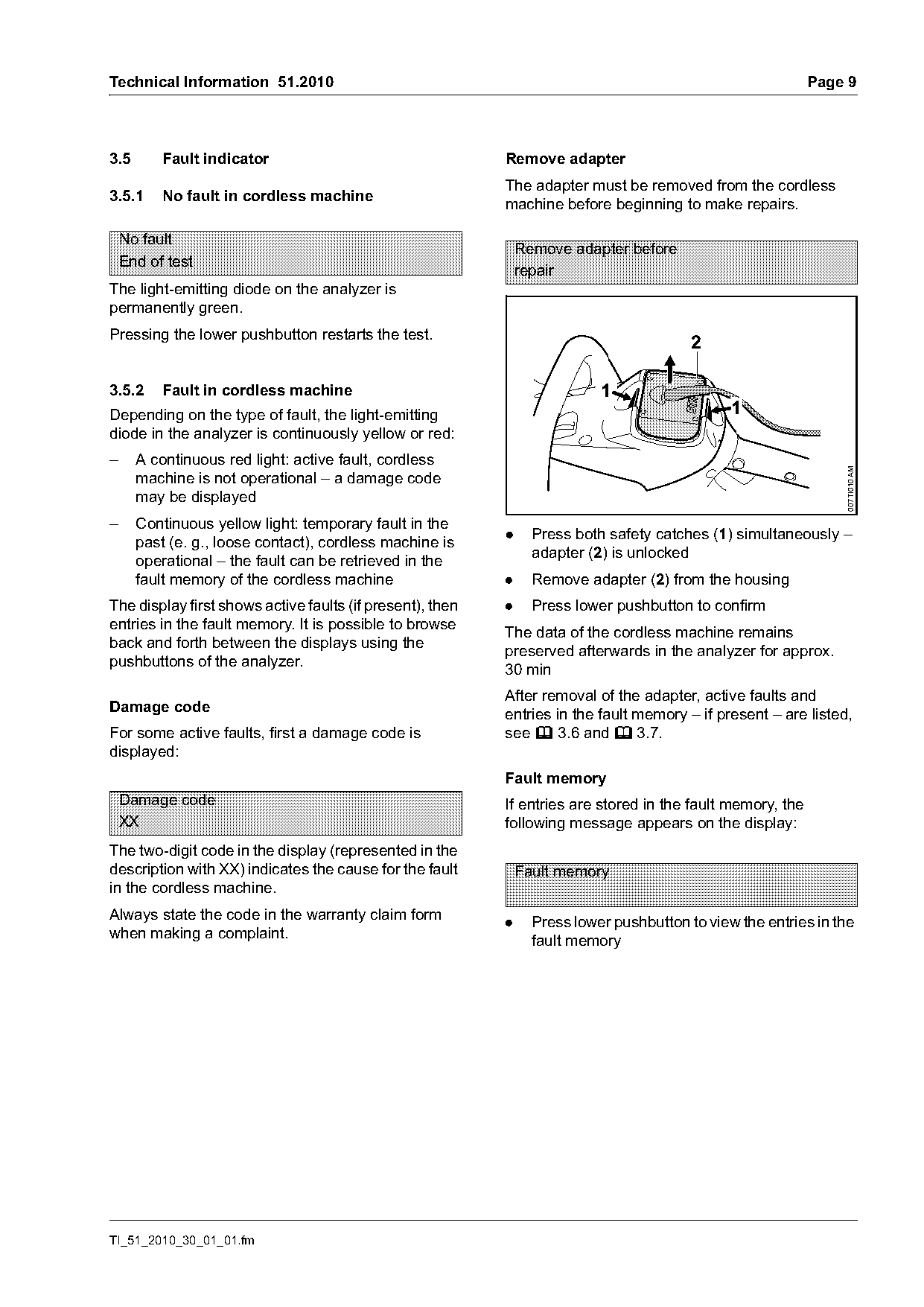
                                                           The adapter must be removed from the cordless
3.5.1     No fault in cordless machine
                                                           machine before beginning to make repairs.

    No fault
                                                               Remove adapter before
    End of test
                                                               repair
The light-emitting diode on the analyzer is
permanently green.
Pressing the lower pushbutton restarts the test.
                                                                                         2

3.5.2     Fault in cordless machine                                        1
Depending on the type of fault, the light-emitting                                             1
diode in the analyzer is continuously yellow or red:
–     A continuous red light: active fault, cordless

                                                                                                                007TI010 AM
      machine is not operational – a damage code
      may be displayed
–     Continuous yellow light: temporary fault in the
      past (e. g., loose contact), cordless machine is     .     Press both safety catches (1) simultaneously –
      operational – the fault can be retrieved in the            adapter (2) is unlocked
      fault memory of the cordless machine                 .     Remove adapter (2) from the housing
The display first shows active faults (if present), then   .     Press lower pushbutton to confirm
entries in the fault memory. It is possible to browse
                                                           The data of the cordless machine remains
back and forth between the displays using the
                                                           preserved afterwards in the analyzer for approx.
pushbuttons of the analyzer.
                                                           30 min
                                                           After removal of the adapter, active faults and
Damage code
                                                           entries in the fault memory – if present – are listed,
For some active faults, first a damage code is             see b 3.6 and b 3.7.
displayed:
                                                           Fault memory
    Damage code                                            If entries are stored in the fault memory, the
    XX                                                     following message appears on the display:
The two-digit code in the display (represented in the
description with XX) indicates the cause for the fault         Fault memory
in the cordless machine.
Always state the code in the warranty claim form
                                                           .     Press lower pushbutton to view the entries in the
when making a complaint.
                                                                 fault memory

TI_51_2010_30_01_01.fm
Page 10 of 21
Text of page 10 — search, copy, screen readers
Page 10                                                Technical Information 51.2010

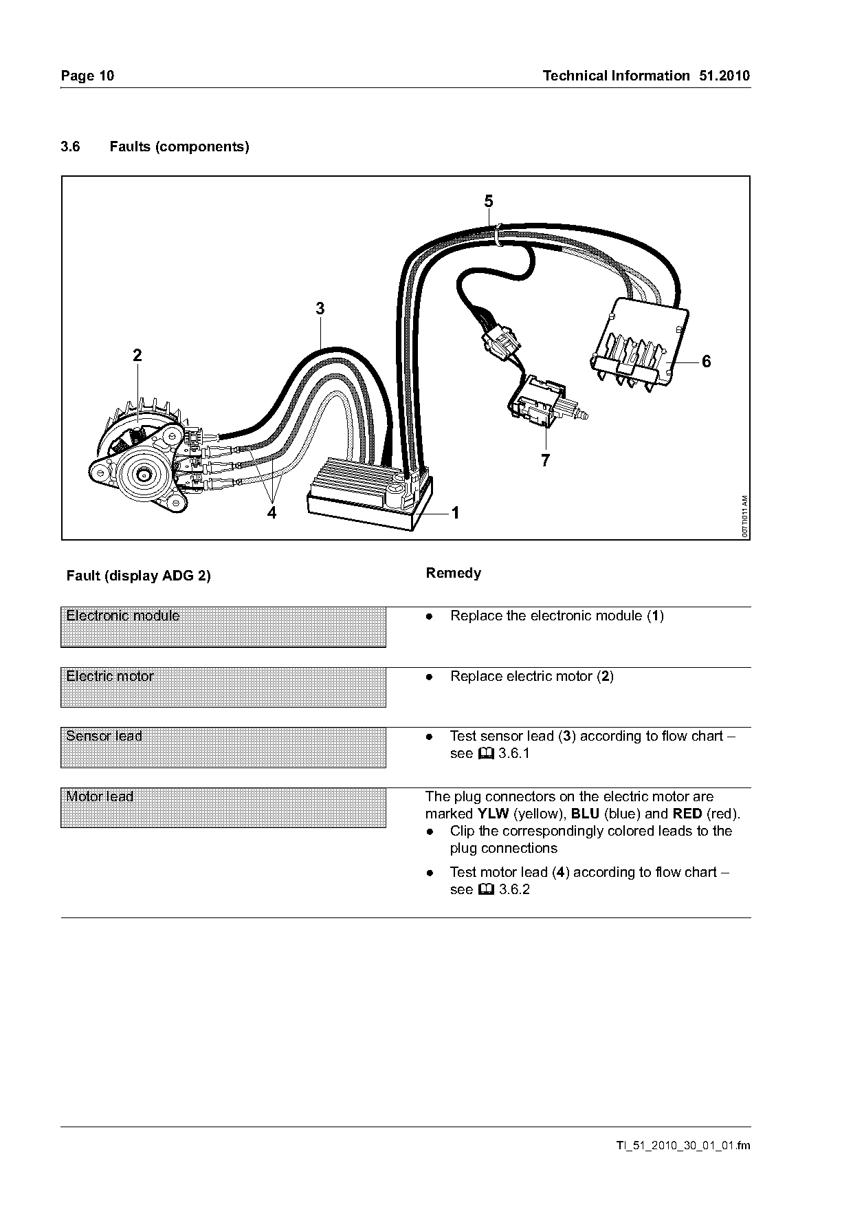
3.6   Faults (components)


          2                                                                       6


                                                                                         007TI011 AM
                            4           1

Fault (display ADG 2)               Remedy

Electronic module                   .   Replace the electronic module (1)

Electric motor                      .   Replace electric motor (2)

Sensor lead                         .   Test sensor lead (3) according to flow chart –
                                        see b 3.6.1

Motor lead                          The plug connectors on the electric motor are
                                    marked YLW (yellow), BLU (blue) and RED (red).
                                    . Clip the correspondingly colored leads to the
                                       plug connections
                                    .   Test motor lead (4) according to flow chart –
                                        see b 3.6.2

                                                                     TI_51_2010_30_01_01.fm
Page 11 of 21
Text of page 11 — search, copy, screen readers
Technical Information 51.2010                                                  Page 11


           2                                                                    6


                                                                                         007TI011 AM
                            4           1

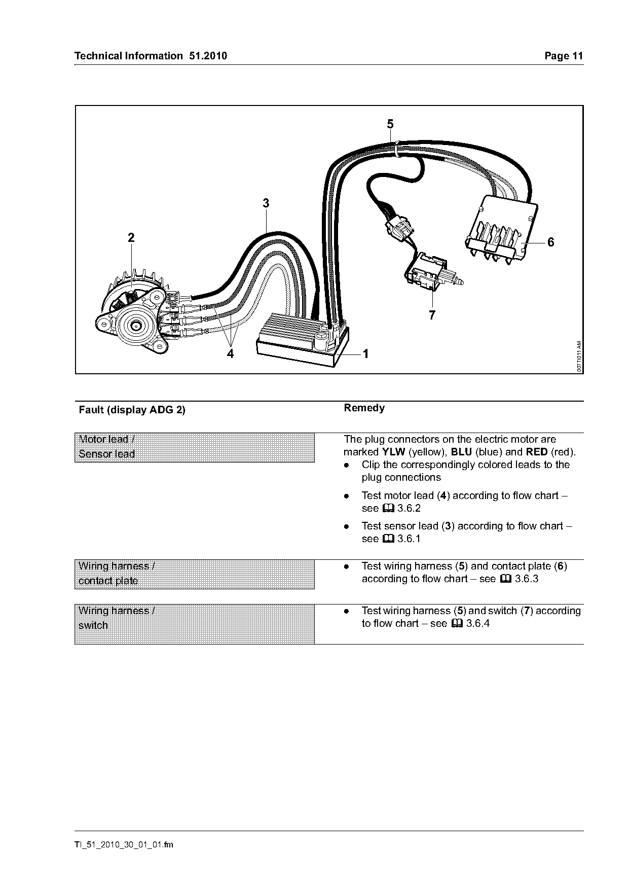
Fault (display ADG 2)               Remedy

Motor lead /                        The plug connectors on the electric motor are
Sensor lead                         marked YLW (yellow), BLU (blue) and RED (red).
                                    . Clip the correspondingly colored leads to the
                                       plug connections
                                    .   Test motor lead (4) according to flow chart –
                                        see b 3.6.2
                                    .   Test sensor lead (3) according to flow chart –
                                        see b 3.6.1

Wiring harness /                    .   Test wiring harness (5) and contact plate (6)
contact plate                           according to flow chart – see b 3.6.3

Wiring harness /                    .   Test wiring harness (5) and switch (7) according
switch                                  to flow chart – see b 3.6.4

TI_51_2010_30_01_01.fm
Page 12 of 21
Text of page 12 — search, copy, screen readers
Page 12                                                                     Technical Information 51.2010

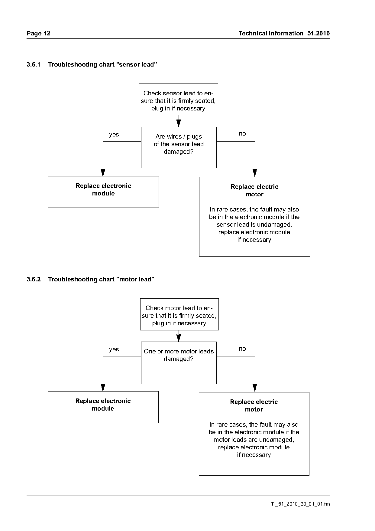
3.6.1   Troubleshooting chart "sensor lead"

                                      Check sensor lead to en-
                                     sure that it is firmly seated,
                                         plug in if necessary

                           yes             Are wires / plugs                no
                                          of the sensor lead
                                              damaged?

                Replace electronic                                       Replace electric
                     module                                                  motor

                                                                 In rare cases, the fault may also
                                                                 be in the electronic module if the
                                                                    sensor lead is undamaged,
                                                                     replace electronic module
                                                                            if necessary

3.6.2   Troubleshooting chart "motor lead"

                                       Check motor lead to en-
                                      sure that it is firmly seated,
                                          plug in if necessary

                           yes        One or more motor leads               no
                                             damaged?

                Replace electronic                                      Replace electric
                     module                                                 motor

                                                                In rare cases, the fault may also
                                                                be in the electronic module if the
                                                                  motor leads are undamaged,
                                                                    replace electronic module
                                                                           if necessary

                                                                                        TI_51_2010_30_01_01.fm
Page 13 of 21
Text of page 13 — search, copy, screen readers
Technical Information 51.2010                                                                Page 13

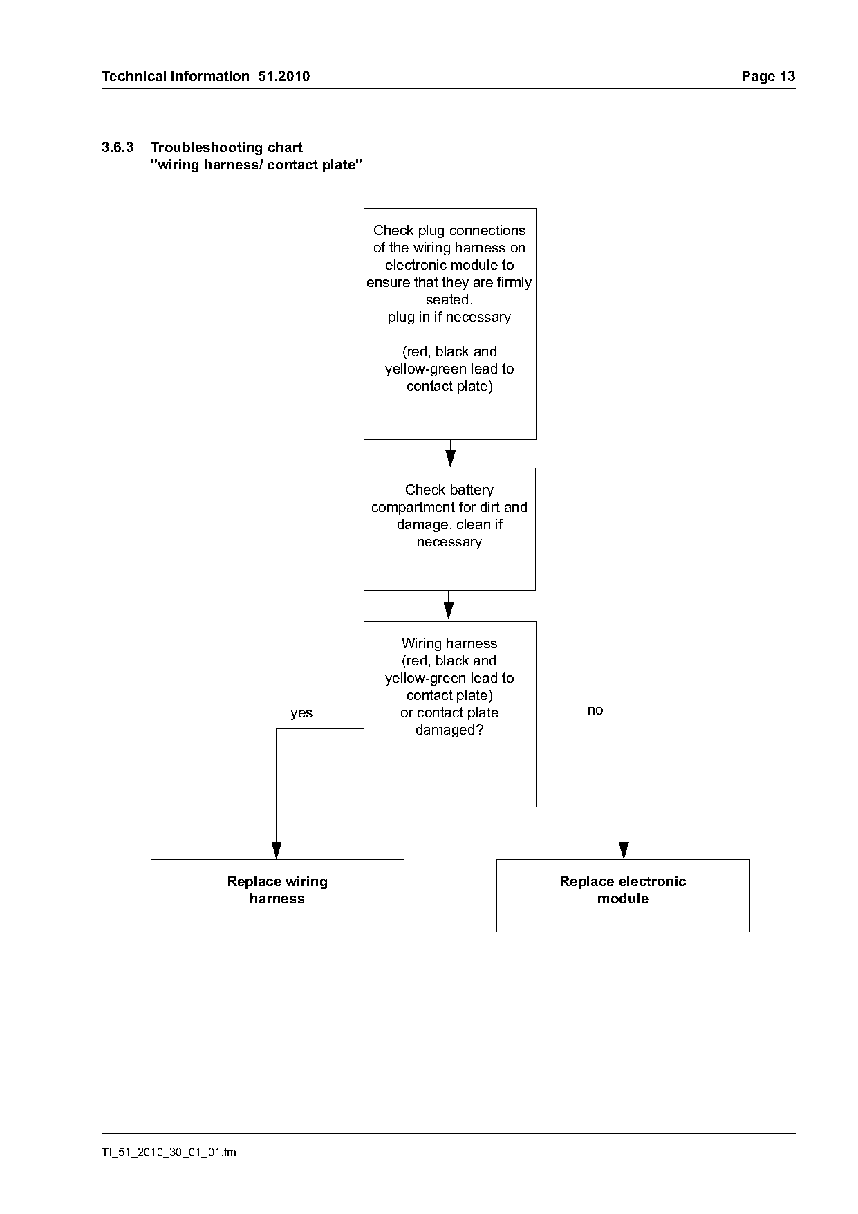
3.6.3   Troubleshooting chart
        "wiring harness/ contact plate"

                                           Check plug connections
                                           of the wiring harness on
                                             electronic module to
                                          ensure that they are firmly
                                                    seated,
                                              plug in if necessary

                                               (red, black and
                                             yellow-green lead to
                                                 contact plate)

                                              Check battery
                                          compartment for dirt and
                                             damage, clean if
                                                necessary

                                               Wiring harness
                                               (red, black and
                                             yellow-green lead to
                                                 contact plate)
                            yes                or contact plate            no
                                                  damaged?

                    Replace wiring                                      Replace electronic
                       harness                                               module

TI_51_2010_30_01_01.fm
Page 14 of 21
Text of page 14 — search, copy, screen readers
Page 14                                                             Technical Information 51.2010

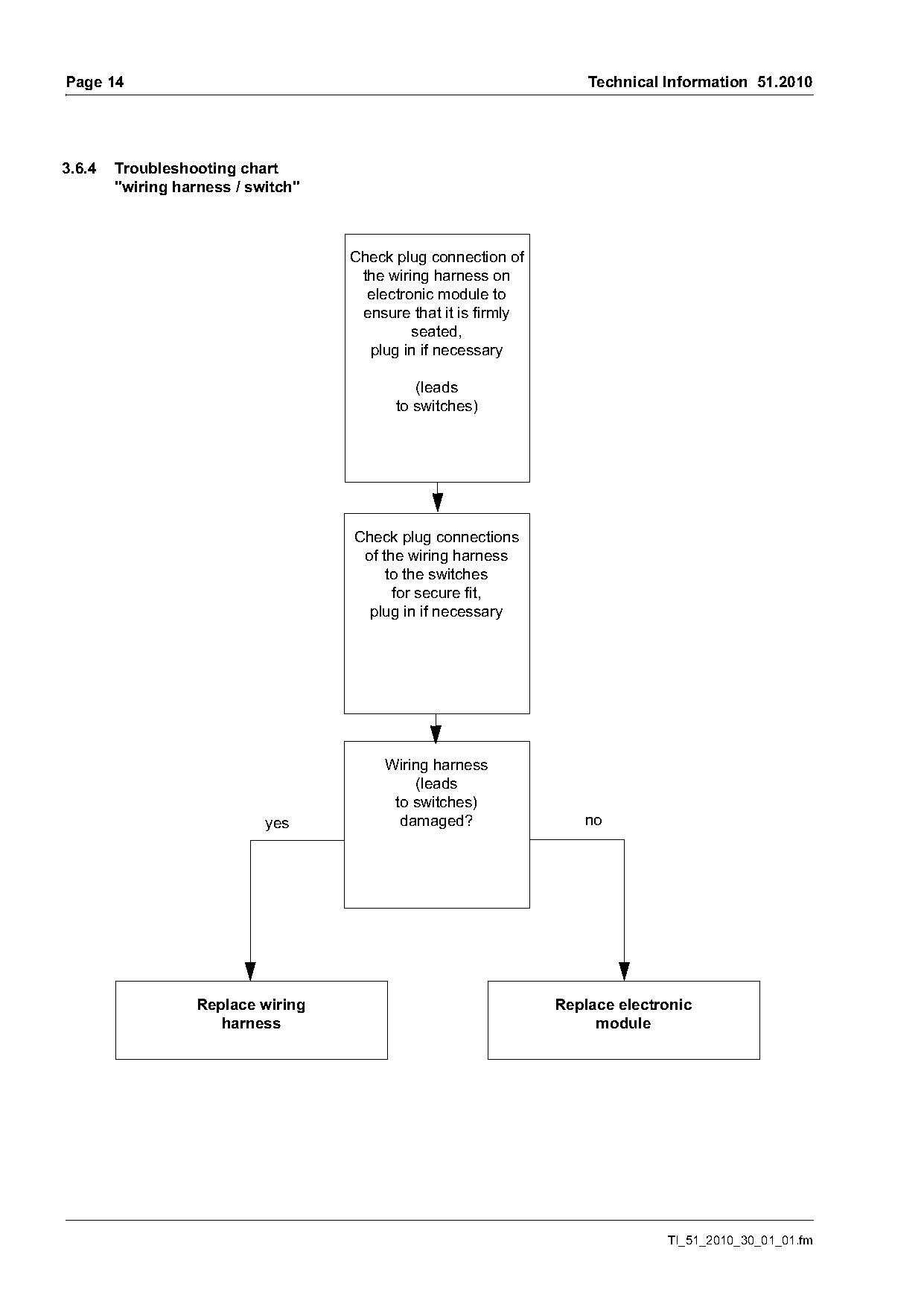
3.6.4   Troubleshooting chart
        "wiring harness / switch"

                                    Check plug connection of
                                     the wiring harness on
                                      electronic module to
                                     ensure that it is firmly
                                             seated,
                                      plug in if necessary

                                             (leads
                                          to switches)

                                    Check plug connections
                                     of the wiring harness
                                         to the switches
                                          for secure fit,
                                      plug in if necessary

                                         Wiring harness
                                             (leads
                                          to switches)
                            yes            damaged?                no

                   Replace wiring                               Replace electronic
                      harness                                        module

                                                                              TI_51_2010_30_01_01.fm
Page 15 of 21
Text of page 15 — search, copy, screen readers
Technical Information 51.2010                                                              Page 15

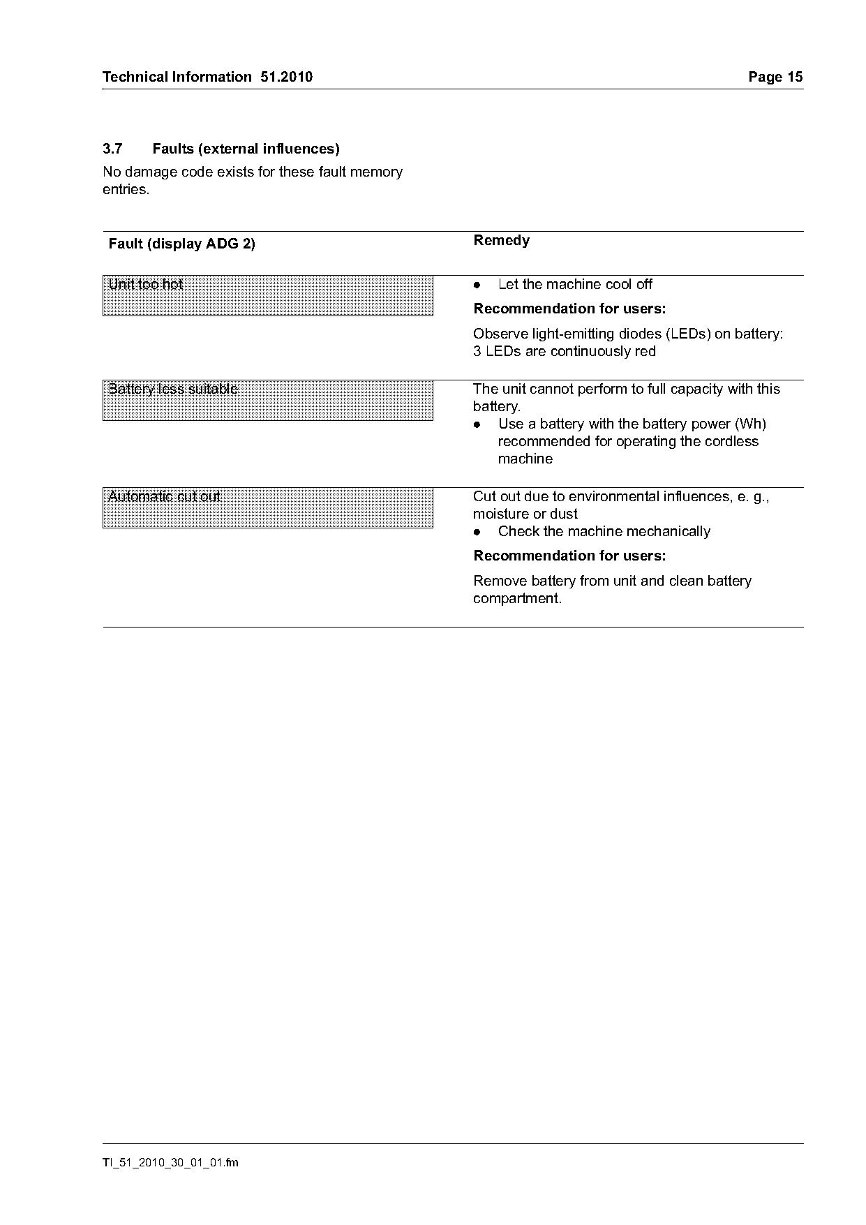
3.7    Faults (external influences)
No damage code exists for these fault memory
entries.

Fault (display ADG 2)                          Remedy

Unit too hot                                   .   Let the machine cool off
                                               Recommendation for users:
                                               Observe light-emitting diodes (LEDs) on battery:
                                               3 LEDs are continuously red

Battery less suitable                          The unit cannot perform to full capacity with this
                                               battery.
                                               . Use a battery with the battery power (Wh)
                                                   recommended for operating the cordless
                                                   machine

Automatic cut out                              Cut out due to environmental influences, e. g.,
                                               moisture or dust
                                               . Check the machine mechanically
                                               Recommendation for users:
                                               Remove battery from unit and clean battery
                                               compartment.

TI_51_2010_30_01_01.fm
Page 16 of 21
Text of page 16 — search, copy, screen readers
Page 16                                                                      Technical Information 51.2010

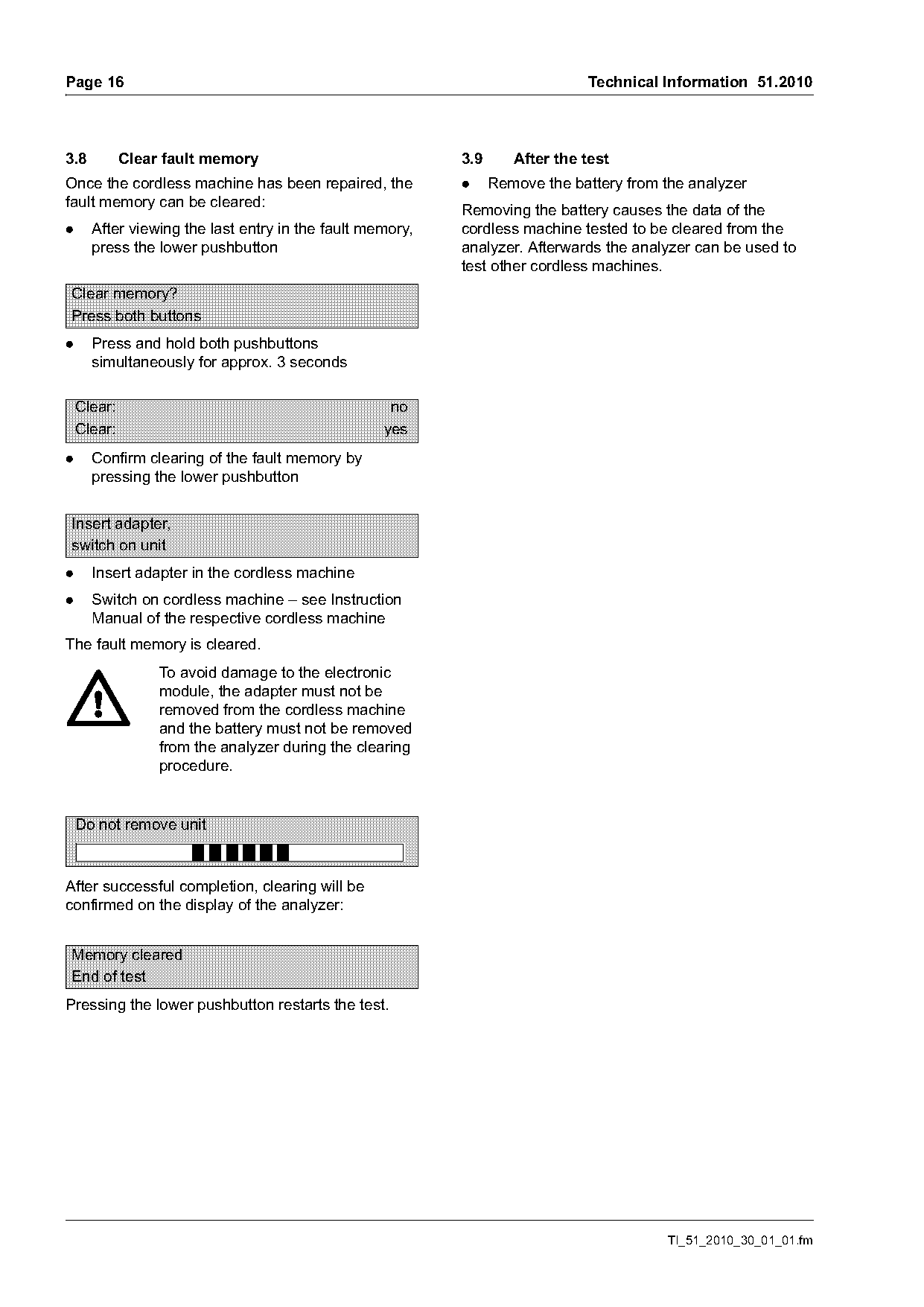
3.8          Clear fault memory                           3.9      After the test
Once the cordless machine has been repaired, the          .     Remove the battery from the analyzer
fault memory can be cleared:                              Removing the battery causes the data of the
.     After viewing the last entry in the fault memory,   cordless machine tested to be cleared from the
      press the lower pushbutton                          analyzer. Afterwards the analyzer can be used to
                                                          test other cordless machines.
Clear memory?
Press both buttons
.     Press and hold both pushbuttons
      simultaneously for approx. 3 seconds

    Clear:                                         no
    Clear:                                        yes
.     Confirm clearing of the fault memory by
      pressing the lower pushbutton

Insert adapter,
switch on unit
.     Insert adapter in the cordless machine
.     Switch on cordless machine – see Instruction
      Manual of the respective cordless machine
The fault memory is cleared.
                  To avoid damage to the electronic
                  module, the adapter must not be
                  removed from the cordless machine
                  and the battery must not be removed
                  from the analyzer during the clearing
                  procedure.

    Do not remove unit

After successful completion, clearing will be
confirmed on the display of the analyzer:

Memory cleared
End of test
Pressing the lower pushbutton restarts the test.

                                                                                        TI_51_2010_30_01_01.fm
Page 17 of 21
Text of page 17 — search, copy, screen readers
Technical Information 51.2010                                                                     Page 17

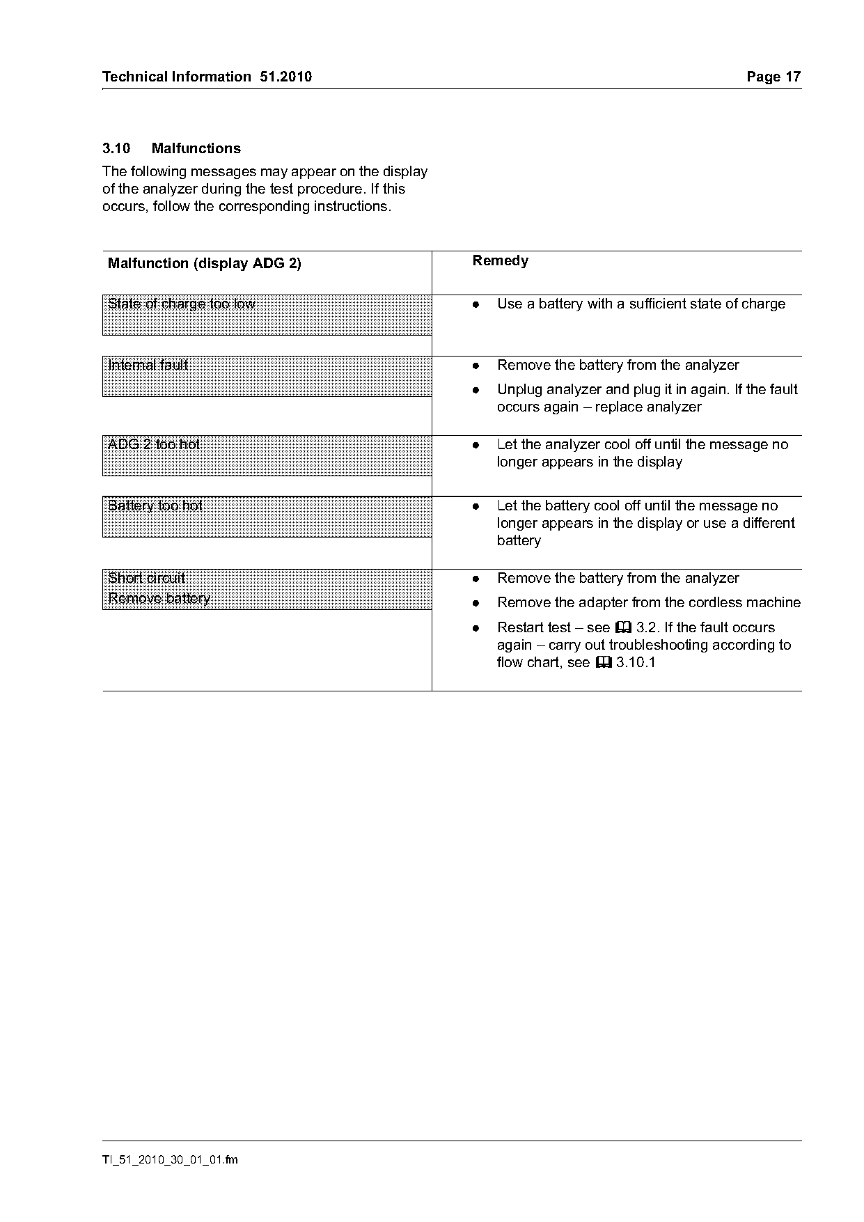
3.10   Malfunctions
The following messages may appear on the display
of the analyzer during the test procedure. If this
occurs, follow the corresponding instructions.

Malfunction (display ADG 2)                          Remedy

State of charge too low                              .   Use a battery with a sufficient state of charge

Internal fault                                       .   Remove the battery from the analyzer
                                                     .   Unplug analyzer and plug it in again. If the fault
                                                         occurs again – replace analyzer

ADG 2 too hot                                        .   Let the analyzer cool off until the message no
                                                         longer appears in the display

Battery too hot                                      .   Let the battery cool off until the message no
                                                         longer appears in the display or use a different
                                                         battery

Short circuit                                        .   Remove the battery from the analyzer
Remove battery                                       .   Remove the adapter from the cordless machine
                                                     .   Restart test – see b 3.2. If the fault occurs
                                                         again – carry out troubleshooting according to
                                                         flow chart, see b 3.10.1

TI_51_2010_30_01_01.fm
Page 18 of 21
Text of page 18 — search, copy, screen readers
Page 18                                                                             Technical Information 51.2010

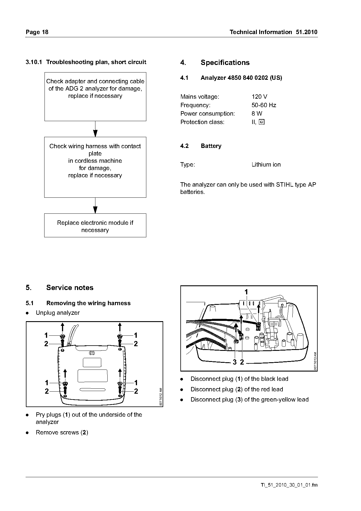
3.10.1 Troubleshooting plan, short circuit                      4.       Specifications

                                                                4.1      Analyzer 4850 840 0202 (US)
         Check adapter and connecting cable
          of the ADG 2 analyzer for damage,
                  replace if necessary                          Mains voltage:                 120 V
                                                                Frequency:                     50-60 Hz
                                                                Power consumption:             8W
                                                                Protection class:              II, E

             Check wiring harness with contact                  4.2      Battery
                           plate
                   in cordless machine
                                                                Type:                          Lithium ion
                       for damage,
                   replace if necessary
                                                                The analyzer can only be used with STIHL type AP
                                                                batteries.

               Replace electronic module if
                       necessary

5.       Service notes
                                                                                           1
5.1      Removing the wiring harness
.     Unplug analyzer

         1                                    1
         2                                    2
                                                                                                                      007TI013 AM

                                                                                     3 2

                                                                .     Disconnect plug (1) of the black lead
         1                                    1
         2                                    2                 .     Disconnect plug (2) of the red lead
                                                  007TI012 AM

                                                                .     Disconnect plug (3) of the green-yellow lead

.     Pry plugs (1) out of the underside of the
      analyzer
.     Remove screws (2)

                                                                                                  TI_51_2010_30_01_01.fm
Page 19 of 21
Text of page 19 — search, copy, screen readers
Technical Information 51.2010                                                                                    Page 19

    1                     3                                                                    1
    2                                                                            1
                                                                                 2
    4

                                                    007TI014 AM

                                                                                                                      007TI016 AM
                                                                                                   3

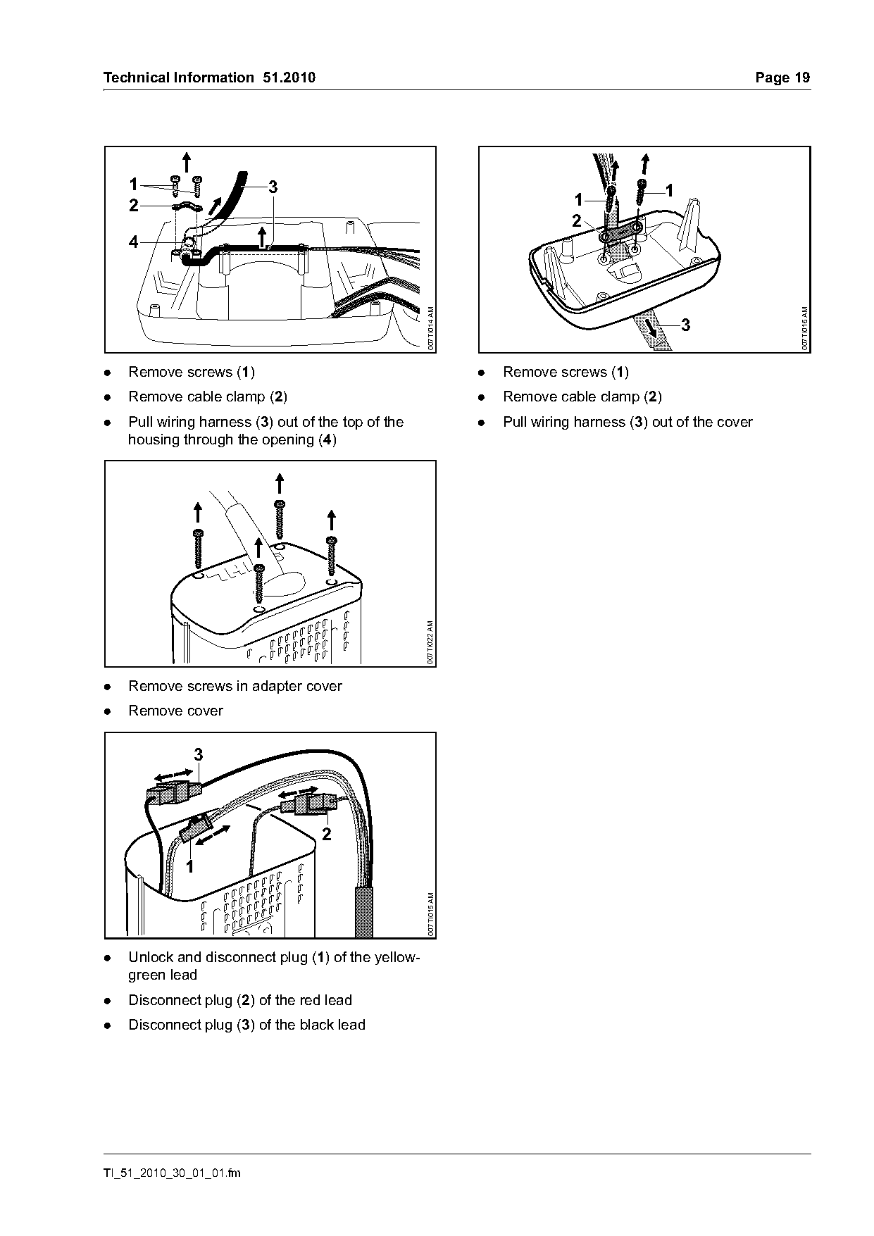
.   Remove screws (1)                                             .   Remove screws (1)
.   Remove cable clamp (2)                                        .   Remove cable clamp (2)
.   Pull wiring harness (3) out of the top of the                 .   Pull wiring harness (3) out of the cover
    housing through the opening (4)
                                                    007TI022 AM

.   Remove screws in adapter cover
.   Remove cover


                                   2
             1
                                                    007TI015 AM

.   Unlock and disconnect plug (1) of the yellow-
    green lead
.   Disconnect plug (2) of the red lead
.   Disconnect plug (3) of the black lead

TI_51_2010_30_01_01.fm
Page 20 of 21
Text of page 20 — search, copy, screen readers
Page 20                                                                              Technical Information 51.2010

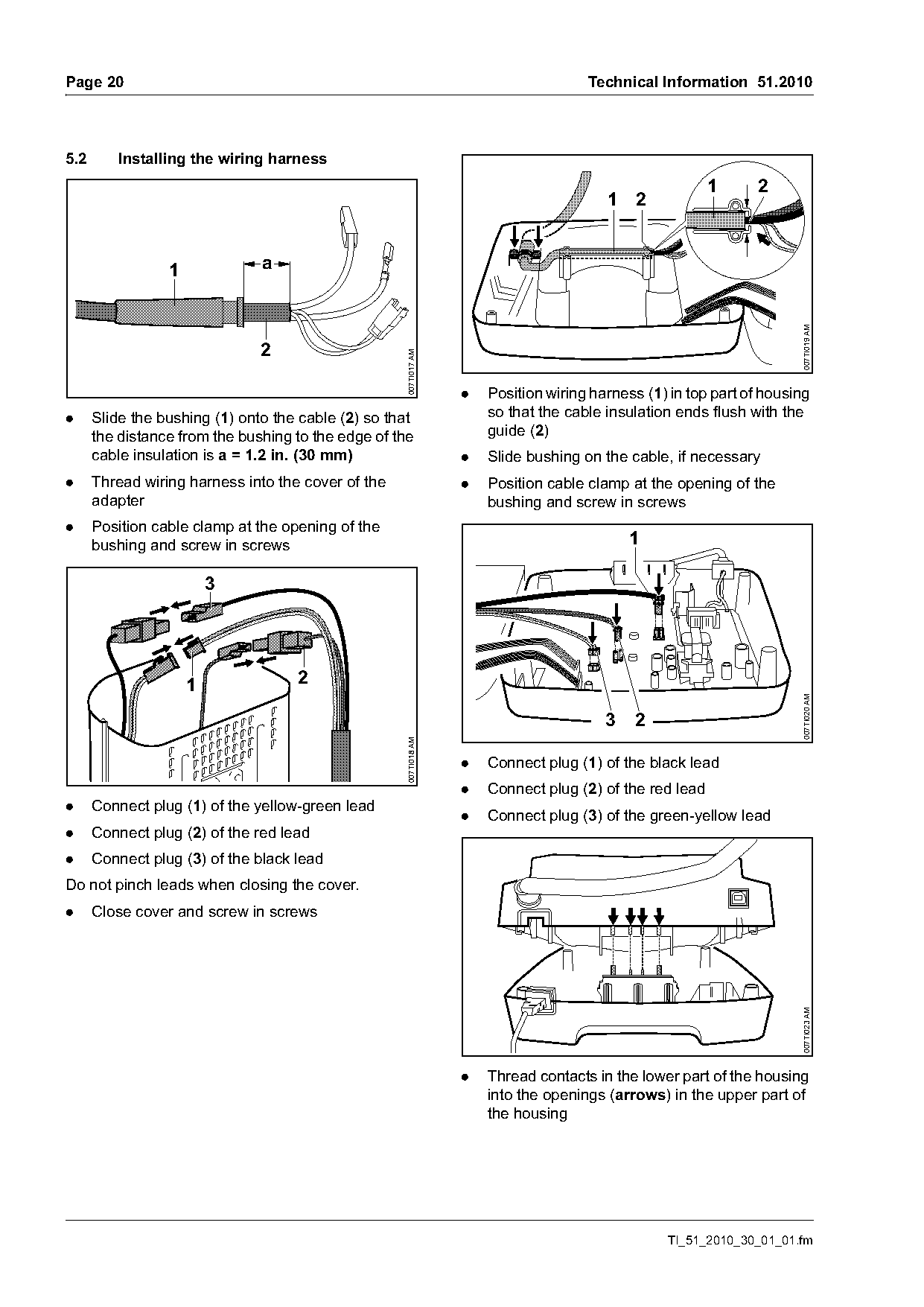
5.2      Installing the wiring harness
                                                                                                         1     2
                                                                                        1 2

                 1             a

                                                                                                                      007TI019 AM
                               2

                                                    007TI017 AM
                                                                  .   Position wiring harness (1) in top part of housing
.     Slide the bushing (1) onto the cable (2) so that                so that the cable insulation ends flush with the
      the distance from the bushing to the edge of the                guide (2)
      cable insulation is a = 1.2 in. (30 mm)                     .   Slide bushing on the cable, if necessary
.     Thread wiring harness into the cover of the                 .   Position cable clamp at the opening of the
      adapter                                                         bushing and screw in screws
.     Position cable clamp at the opening of the
      bushing and screw in screws                                                           1


                     1              2

                                                                                                                      007TI020 AM
                                                                                        3   2
                                                    007TI018 AM
                                                    007TI015

                                                                  .   Connect plug (1) of the black lead
                                                                  .   Connect plug (2) of the red lead
.     Connect plug (1) of the yellow-green lead
                                                                  .   Connect plug (3) of the green-yellow lead
.     Connect plug (2) of the red lead
.     Connect plug (3) of the black lead
Do not pinch leads when closing the cover.
.     Close cover and screw in screws
                                                                                                                      007TI023 AM

                                                                  .   Thread contacts in the lower part of the housing
                                                                      into the openings (arrows) in the upper part of
                                                                      the housing

                                                                                                 TI_51_2010_30_01_01.fm
Page 21 of 21
Text of page 21 — search, copy, screen readers
Technical Information 51.2010                                                                                  Page 21

                                                                     5.4       Tightening torques

         2                                         2
         1                                         1                 Part(s)                 Thread   Tightening
                                                                                                      torque
                                                                     Cover / adapter         M3x25    0.9 lbf. ft.
                                                                     housing                          (1.2 Nm)

         2                                         2                 Cable clamp / cover P3.5x12      0.9 lbf. ft.

                                                       007TI021 AM
         1                                         1                                                  (1.2 Nm)

                                                                     Upper / lower part of   P3x18    0.6 lbf. ft.
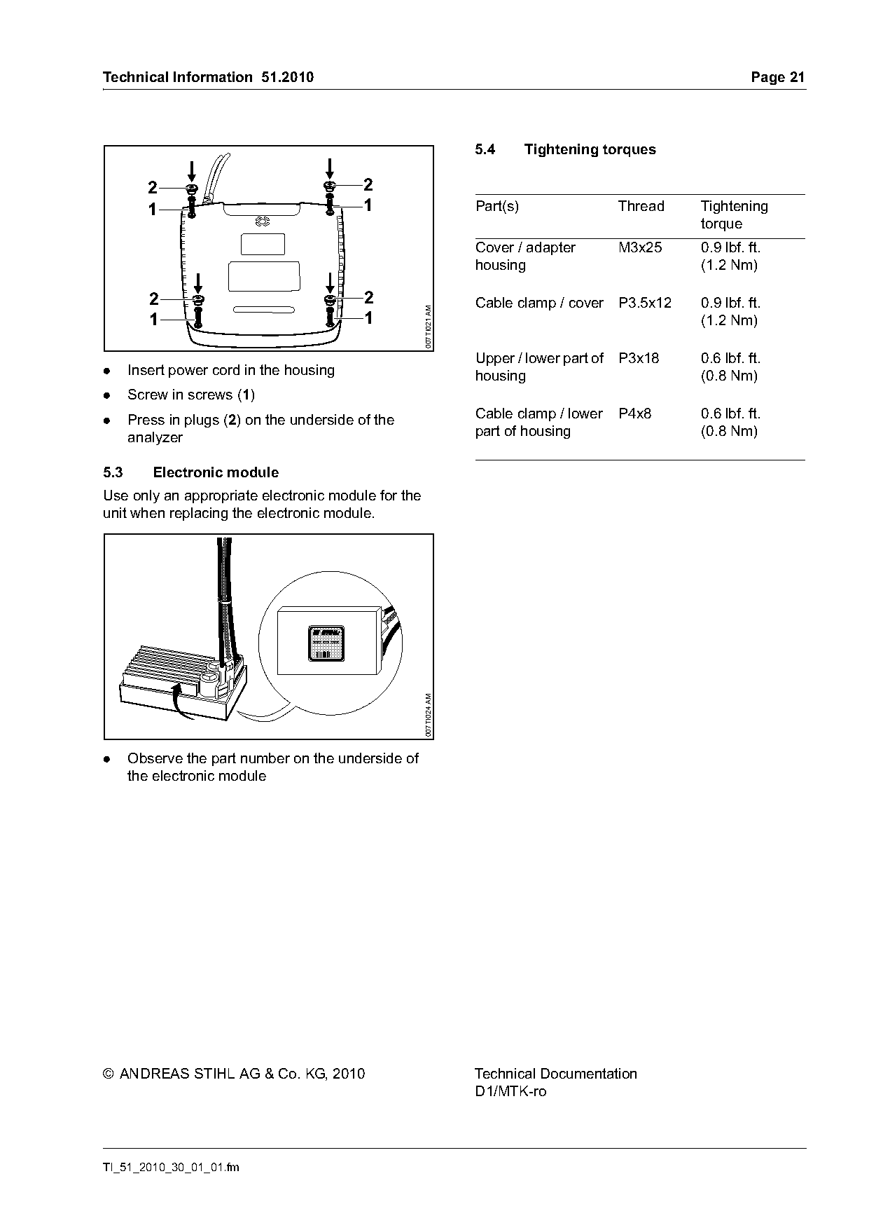
.     Insert power cord in the housing                               housing                          (0.8 Nm)
.     Screw in screws (1)
.     Press in plugs (2) on the underside of the                     Cable clamp / lower     P4x8     0.6 lbf. ft.
      analyzer                                                       part of housing                  (0.8 Nm)

5.3      Electronic module
Use only an appropriate electronic module for the
unit when replacing the electronic module.

                                   XXXX-XXX-XXXX
                                                       007TI024 AM

.     Observe the part number on the underside of
      the electronic module

© ANDREAS STIHL AG & Co. KG, 2010                                    Technical Documentation
                                                                     D1/MTK-ro

TI_51_2010_30_01_01.fm
Most of these PDFs embed fonts with a shifted character map, so the text above was recovered rather than copied — read it as a faithful but imperfect transcription, and treat the page image above each block as the authority where the two disagree — the figures exist only there, because they are vector drawings that text extraction cannot keep.