Technical Information · issue 9 of 2011
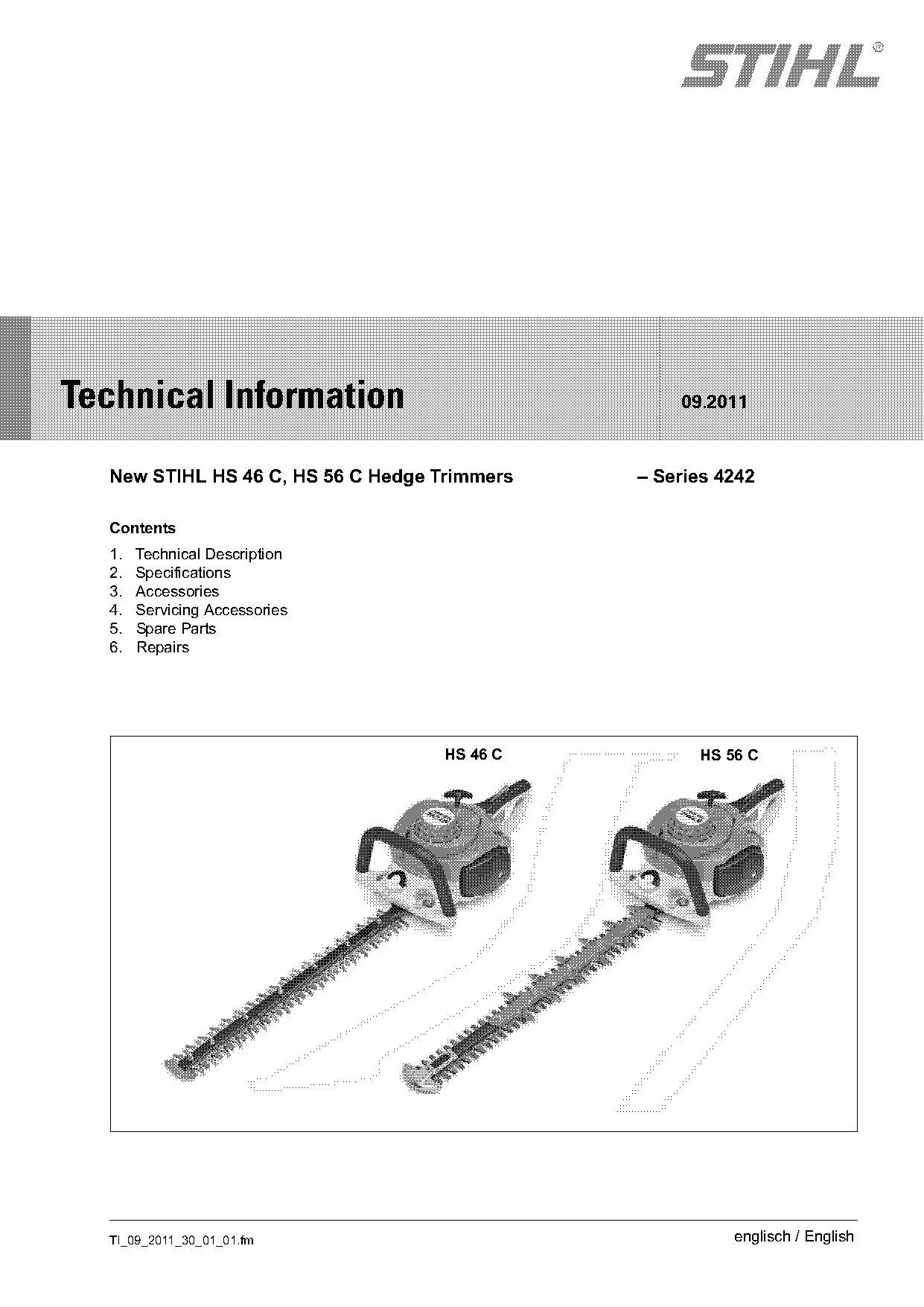
New STIHL HS 46 C, HS 56 C Hedge Trimmers
IssueTI 9/2011
Full text
Page 1 of 12
Text of page 1 — search, copy, screen readers
STIH)

Technical Information                             09.2011

  New STIHL HS 46 C, HS 56 C Hedge Trimmers   – Series 4242

  Contents
  1.   Technical Description
  2.   Specifications
  3.   Accessories
  4.   Servicing Accessories
  5.   Spare Parts
  6.   Repairs

                                   HS 46 C          HS 56 C

  TI_09_2011_30_01_01.fm                                englisch / English
Page 2 of 12
Text of page 2 — search, copy, screen readers
Page 2                                                                       Technical Information 09.2011

The new STIHL HS 46 C and HS 56 C hedge                   1.      Technical Description
trimmers are the latest additions to that product line.
The new models are characterized by the following         1.1     Master Control Lever™
features:
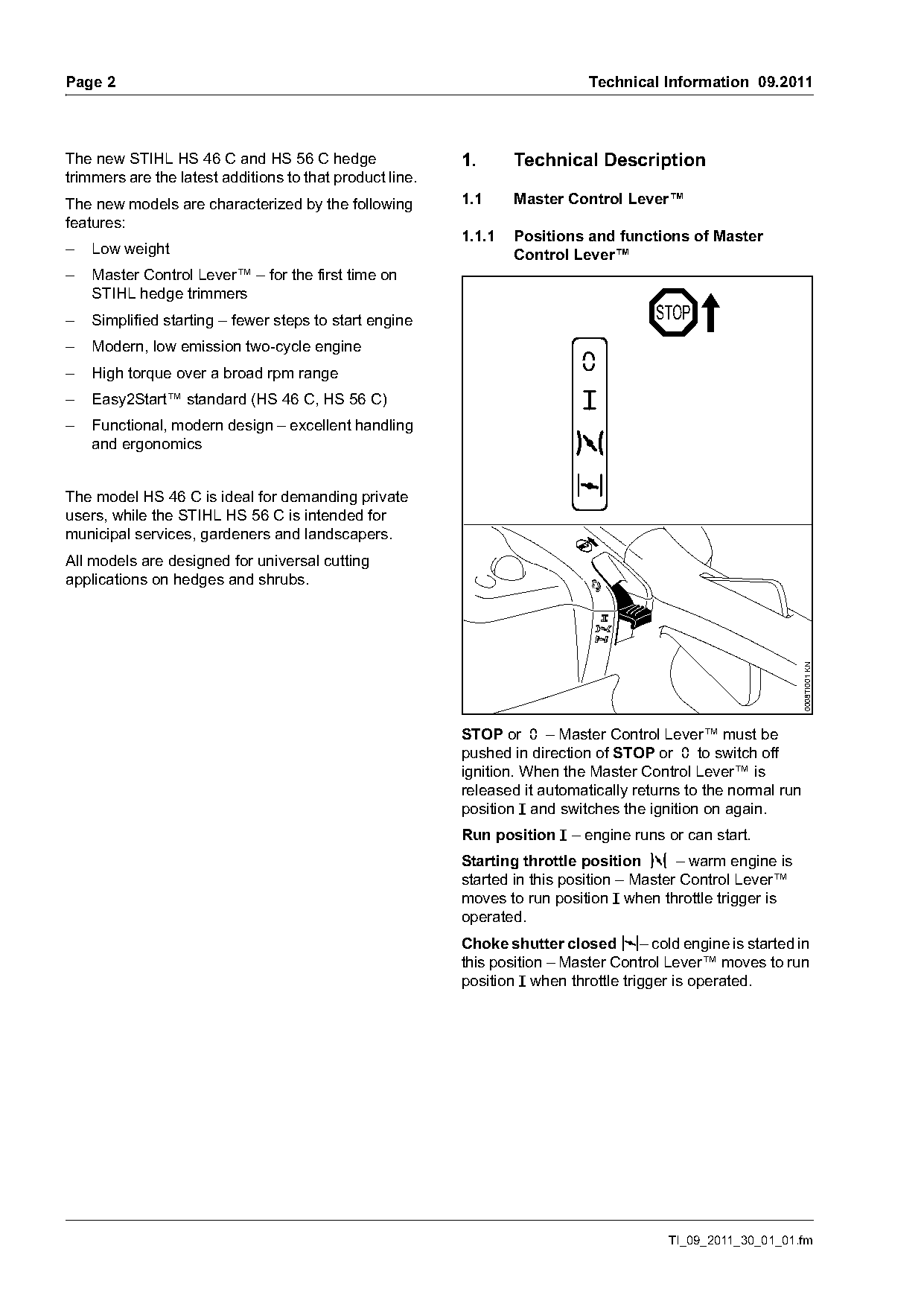
                                                          1.1.1   Positions and functions of Master
–   Low weight                                                    Control Lever™
–   Master Control Lever™ – for the first time on
    STIHL hedge trimmers
–   Simplified starting – fewer steps to start engine                                  STOP
–   Modern, low emission two-cycle engine
–   High torque over a broad rpm range                                      0
–   Easy2Start™ standard (HS 46 C, HS 56 C)
–   Functional, modern design – excellent handling
    and ergonomics

The model HS 46 C is ideal for demanding private
users, while the STIHL HS 56 C is intended for
municipal services, gardeners and landscapers.
All models are designed for universal cutting
applications on hedges and shrubs.

                                                                                                                0008TI001 KN
                                                          STOP or † – Master Control Lever™ must be
                                                          pushed in direction of STOP or † to switch off
                                                          ignition. When the Master Control Lever™ is
                                                          released it automatically returns to the normal run
                                                          position F and switches the ignition on again.
                                                          Run position F – engine runs or can start.
                                                          Starting throttle position n – warm engine is
                                                          started in this position – Master Control Lever™
                                                          moves to run position F when throttle trigger is
                                                          operated.
                                                          Choke shutter closed l– cold engine is started in
                                                          this position – Master Control Lever™ moves to run
                                                          position F when throttle trigger is operated.

                                                                                         TI_09_2011_30_01_01.fm
Page 3 of 12
Text of page 3 — search, copy, screen readers
Technical Information 09.2011                                                                                      Page 3

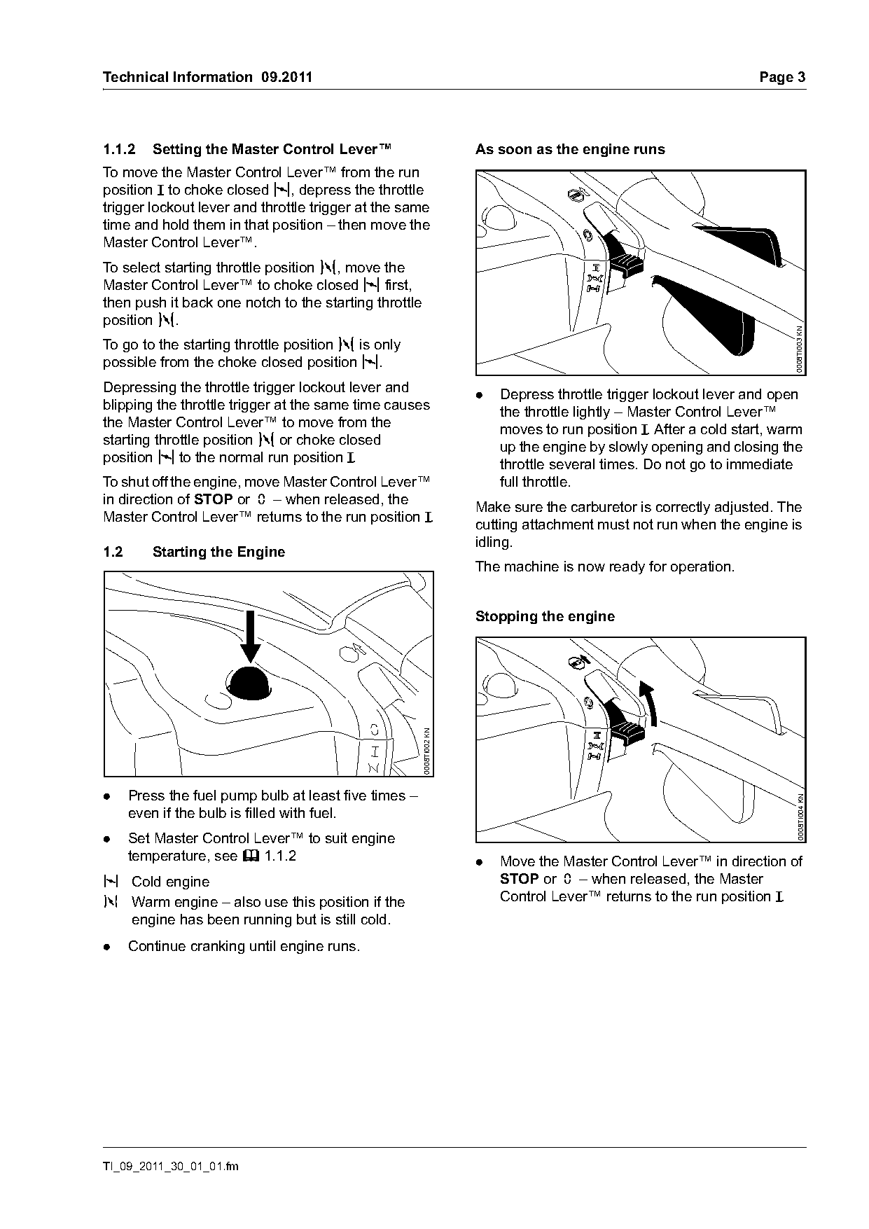
1.1.2    Setting the Master Control Lever™                            As soon as the engine runs
To move the Master Control Lever™ from the run
position F to choke closed l, depress the throttle
trigger lockout lever and throttle trigger at the same
time and hold them in that position – then move the
Master Control Lever™.
To select starting throttle position n, move the
Master Control Lever™ to choke closed l first,
then push it back one notch to the starting throttle
position n.

                                                                                                                         0008TI003 KN
To go to the starting throttle position n is only
possible from the choke closed position l.
Depressing the throttle trigger lockout lever and
                                                                      .   Depress throttle trigger lockout lever and open
blipping the throttle trigger at the same time causes
                                                                          the throttle lightly – Master Control Lever™
the Master Control Lever™ to move from the
                                                                          moves to run position F. After a cold start, warm
starting throttle position n or choke closed
                                                                          up the engine by slowly opening and closing the
position l to the normal run position F.
                                                                          throttle several times. Do not go to immediate
To shut off the engine, move Master Control Lever™                        full throttle.
in direction of STOP or † – when released, the
                                                                      Make sure the carburetor is correctly adjusted. The
Master Control Lever™ returns to the run position F.
                                                                      cutting attachment must not run when the engine is
                                                                      idling.
1.2      Starting the Engine
                                                                      The machine is now ready for operation.

                                                                      Stopping the engine
                                                       0008TI002 KN

.     Press the fuel pump bulb at least five times –                                                                       0008TI004 KN

      even if the bulb is filled with fuel.
.     Set Master Control Lever™ to suit engine
      temperature, see b 1.1.2                                        .   Move the Master Control Lever™ in direction of
l Cold engine                                                             STOP or † – when released, the Master
n Warm engine – also use this position if the                             Control Lever™ returns to the run position F.
      engine has been running but is still cold.
.     Continue cranking until engine runs.

TI_09_2011_30_01_01.fm
Page 4 of 12
Text of page 4 — search, copy, screen readers
Page 4                                                                                        Technical Information 09.2011

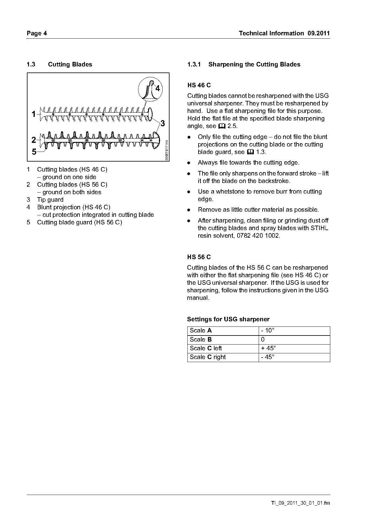
1.3         Cutting Blades                                                1.3.1   Sharpening the Cutting Blades

                                                                          HS 46 C
                                                       4
                                                                          Cutting blades cannot be resharpened with the USG
                                                                          universal sharpener. They must be resharpened by
                                                                          hand. Use a flat sharpening file for this purpose.
    1                                                                     Hold the flat file at the specified blade sharpening
                                                           3              angle, see b 2.5.
                                                                          .   Only file the cutting edge – do not file the blunt
    2

                                                           0008TI017 KN
                                                                              projections on the cutting blade or the cutting
    5                                                                         blade guard, see b 1.3.
                                                                          .   Always file towards the cutting edge.
1       Cutting blades (HS 46 C)
                                                                          .   The file only sharpens on the forward stroke – lift
        – ground on one side
                                                                              it off the blade on the backstroke.
2       Cutting blades (HS 56 C)
        – ground on both sides                                            .   Use a whetstone to remove burr from cutting
3       Tip guard                                                             edge.
4       Blunt projection (HS 46 C)                                        .   Remove as little cutter material as possible.
        – cut protection integrated in cutting blade
5       Cutting blade guard (HS 56 C)                                     .   After sharpening, clean filing or grinding dust off
                                                                              the cutting blades and spray blades with STIHL
                                                                              resin solvent, 0782 420 1002.

                                                                          HS 56 C
                                                                          Cutting blades of the HS 56 C can be resharpened
                                                                          with either the flat sharpening file (see HS 46 C) or
                                                                          the USG universal sharpener. If the USG is used for
                                                                          sharpening, follow the instructions given in the USG
                                                                          manual.

                                                                          Settings for USG sharpener
                                                                          Scale A                     - 10°
                                                                          Scale B                     0
                                                                          Scale C left                + 45°
                                                                          Scale C right               - 45°

                                                                                                          TI_09_2011_30_01_01.fm
Page 5 of 12
Text of page 5 — search, copy, screen readers
Technical Information 09.2011                                                                                      Page 5

1.4      Spark Plug                                                1.4.2   Installing the Spark Plug
                                                                   .   Fit the spark plug and screw it in by hand.
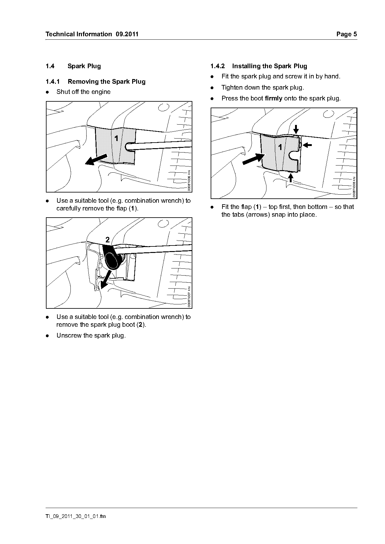
1.4.1    Removing the Spark Plug
                                                                   .   Tighten down the spark plug.
.     Shut off the engine
                                                                   .   Press the boot firmly onto the spark plug.

                                                    0008TI006 KN

                                                                                                                         0008TI008 KN
.     Use a suitable tool (e.g. combination wrench) to
      carefully remove the flap (1).                               .   Fit the flap (1) – top first, then bottom – so that
                                                                       the tabs (arrows) snap into place.

                       2
                                                    0008TI007 KN

.     Use a suitable tool (e.g. combination wrench) to
      remove the spark plug boot (2).
.     Unscrew the spark plug.

TI_09_2011_30_01_01.fm
Page 6 of 12
Text of page 6 — search, copy, screen readers
Page 6                                                                                    Technical Information 09.2011

1.5      Antivibration System                                        2.      Specifications
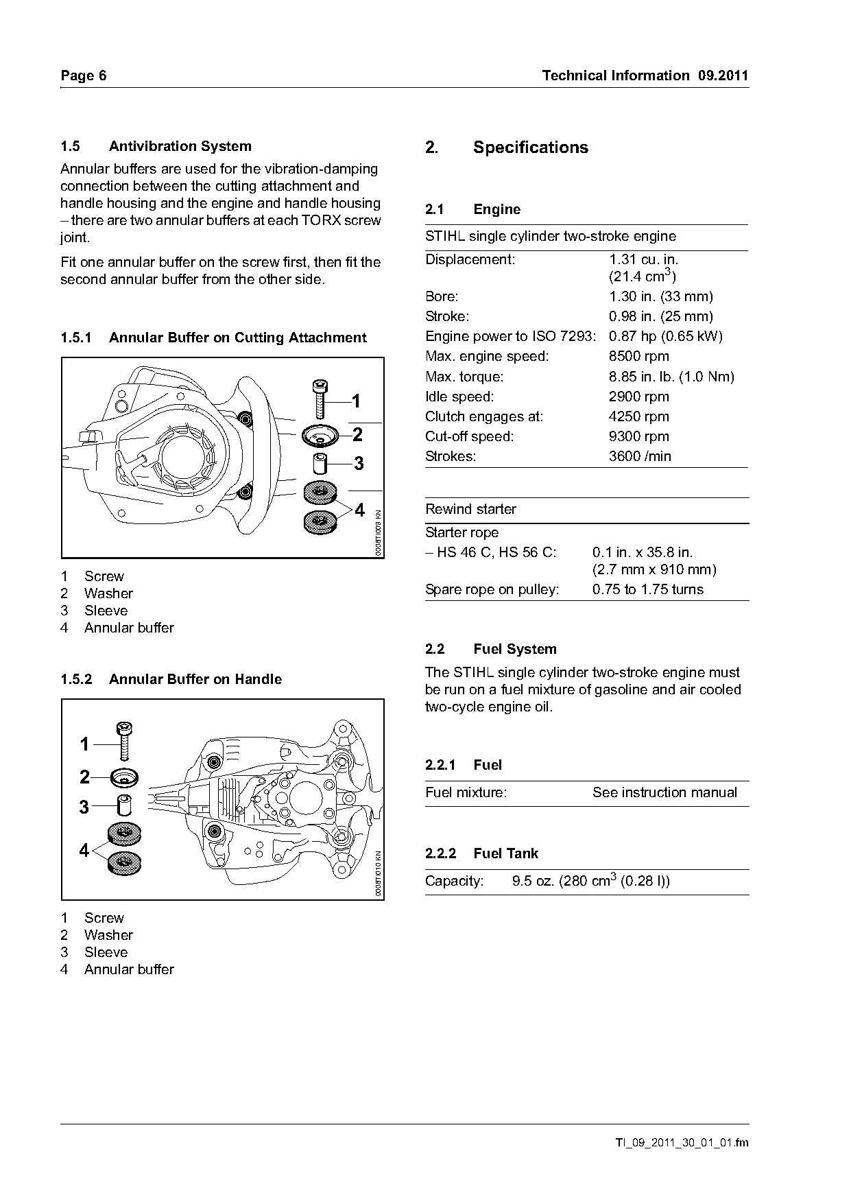
Annular buffers are used for the vibration-damping
connection between the cutting attachment and
handle housing and the engine and handle housing                     2.1     Engine
– there are two annular buffers at each TORX screw
joint.                                                               STIHL single cylinder two-stroke engine
Fit one annular buffer on the screw first, then fit the              Displacement:             1.31 cu. in.
second annular buffer from the other side.                                                     (21.4 cm3)
                                                                     Bore:                     1.30 in. (33 mm)
                                                                     Stroke:                   0.98 in. (25 mm)
1.5.1    Annular Buffer on Cutting Attachment                        Engine power to ISO 7293: 0.87 hp (0.65 kW)
                                                                     Max. engine speed:        8500 rpm
                                                                     Max. torque:              8.85 in. lb. (1.0 Nm)
                                                 1                   Idle speed:               2900 rpm
                                                                     Clutch engages at:        4250 rpm
                                                  2                  Cut-off speed:            9300 rpm
                                                                     Strokes:                  3600 /min
                                                  3

                                                  4                  Rewind starter
                                                      0008TI009 KN

                                                                     Starter rope
                                                                     – HS 46 C, HS 56 C:          0.1 in. x 35.8 in.
                                                                                                  (2.7 mm x 910 mm)
1     Screw
2     Washer                                                         Spare rope on pulley:        0.75 to 1.75 turns
3     Sleeve
4     Annular buffer
                                                                     2.2     Fuel System
                                                                     The STIHL single cylinder two-stroke engine must
1.5.2    Annular Buffer on Handle
                                                                     be run on a fuel mixture of gasoline and air cooled
                                                                     two-cycle engine oil.

    1
                                                                     2.2.1   Fuel
    2
                                                                     Fuel mixture:                See instruction manual
    3

    4                                                                2.2.2   Fuel Tank
                                                      0008TI010 KN

                                                                     Capacity:       9.5 oz. (280 cm3 (0.28 l))

1     Screw
2     Washer
3     Sleeve
4     Annular buffer

                                                                                                      TI_09_2011_30_01_01.fm
Page 7 of 12
Text of page 7 — search, copy, screen readers
Technical Information 09.2011                                                                      Page 7

2.2.3    Carburetor                                    2.5    Cutting Attachment
All position diaphragm carburetor with internal fuel                             HS 46 C      HS 56 C
pump, limiter caps on high speed screw (H) and         Cutting length:           22 in.       24 in.
low speed screw (L).                                                             (550 mm)     (600 mm)
Basic setting:                                         Tooth spacing:            1.18 in.     1.34 in.
High speed                                                                       (30 mm)      (34 mm)
screw (H):                 Open 2 full turns           Sharpening angle:         35°          45°
Low speed screw (L):
                           Open 1 full turn
Standard setting:                                      2.6    Weight
High speed                 3/4 Open 3/4 turn (no       dry, with cutting attachment
screw (H):                 further than stop)          HS 46 C:                       9.5 lbs. (4.3 kg)
Low speed screw (L):       3/4 Open 3/4 turn (no       HS 56 C:                       9.9 lbs. (4.5 kg)
                           further than stop)

                                                       2.7    Noise and Vibration Data
2.3      Ignition System
                                                       See instruction manual. For further details on
Ignition module with integrated electronic speed       compliance with vibration Directive 2002/44/EC see
governor                                               www.stihl.com/vib/.
Spark plug (resistor type):    NGK CMR6H,
                               BOSCH USR4AC
Electrode gap:                 0.020 in. (0.5 mm)

2.4      Gearbox
Gear ratio:                1:5.1
Strokes:                   3600 /min
Lubricant:                 STIHL gear lubricant for
                           hedge trimmers
Initial capacity:          12 g
Relubrication1):           up to 5 g
1)
      Commercial usage only – check every 25 hours
      of operation and relubricate if necessary,
      see b 6.2

TI_09_2011_30_01_01.fm
Page 8 of 12
Text of page 8 — search, copy, screen readers
Page 8                                                                      Technical Information 09.2011

3.       Accessories
Part Name                             Part No.        Application
STIHL gear lubricant for hedge                        Lubricating the gear assembly
trimmers
– 80 g tube                           0781 120 1109
– 225 g tube                          0781 120 1110
STIHL resin solvent (300 ml can)      0782 420 1002   Cleaning and lubricating blades

4.       Servicing Accessories

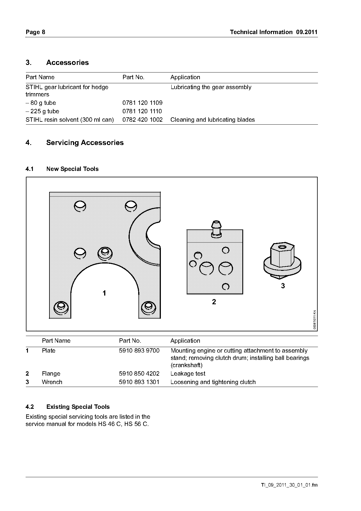
4.1      New Special Tools

                                                                                                3
                              1
                                                                     2
                                                                                                              0008TI011 KN

      Part Name                      Part No.         Application
1     Plate                          5910 893 9700    Mounting engine or cutting attachment to assembly
                                                      stand; removing clutch drum; installing ball bearings
                                                      (crankshaft)
2     Flange                         5910 850 4202    Leakage test
3     Wrench                         5910 893 1301    Loosening and tightening clutch

4.2      Existing Special Tools
Existing special servicing tools are listed in the
service manual for models HS 46 C, HS 56 C.

                                                                                        TI_09_2011_30_01_01.fm
Page 9 of 12
Text of page 9 — search, copy, screen readers
Technical Information 09.2011                                                                 Page 9

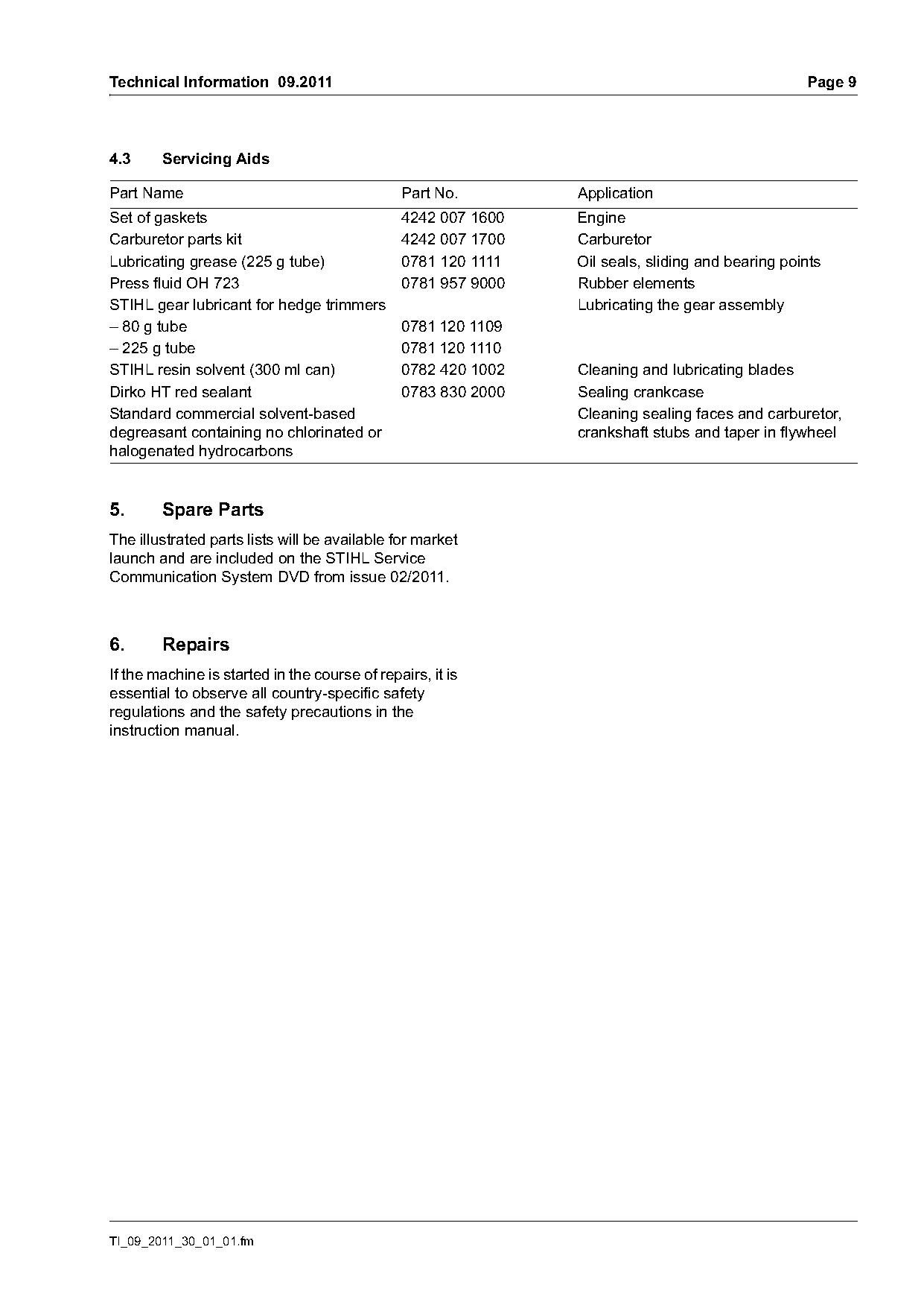
4.3     Servicing Aids

Part Name                                      Part No.     Application
Set of gaskets                          4242 007 1600       Engine
Carburetor parts kit                    4242 007 1700       Carburetor
Lubricating grease (225 g tube)         0781 120 1111       Oil seals, sliding and bearing points
Press fluid OH 723                      0781 957 9000       Rubber elements
STIHL gear lubricant for hedge trimmers                     Lubricating the gear assembly
– 80 g tube                             0781 120 1109
– 225 g tube                            0781 120 1110
STIHL resin solvent (300 ml can)        0782 420 1002       Cleaning and lubricating blades
Dirko HT red sealant                    0783 830 2000       Sealing crankcase
Standard commercial solvent-based                           Cleaning sealing faces and carburetor,
degreasant containing no chlorinated or                     crankshaft stubs and taper in flywheel
halogenated hydrocarbons

5.      Spare Parts
The illustrated parts lists will be available for market
launch and are included on the STIHL Service
Communication System DVD from issue 02/2011.

6.      Repairs
If the machine is started in the course of repairs, it is
essential to observe all country-specific safety
regulations and the safety precautions in the
instruction manual.

TI_09_2011_30_01_01.fm
Page 10 of 12
Text of page 10 — search, copy, screen readers
Page 10                                                                         Technical Information 09.2011

6.1       Carburetor                                      6.2       Lubricating the Gearbox

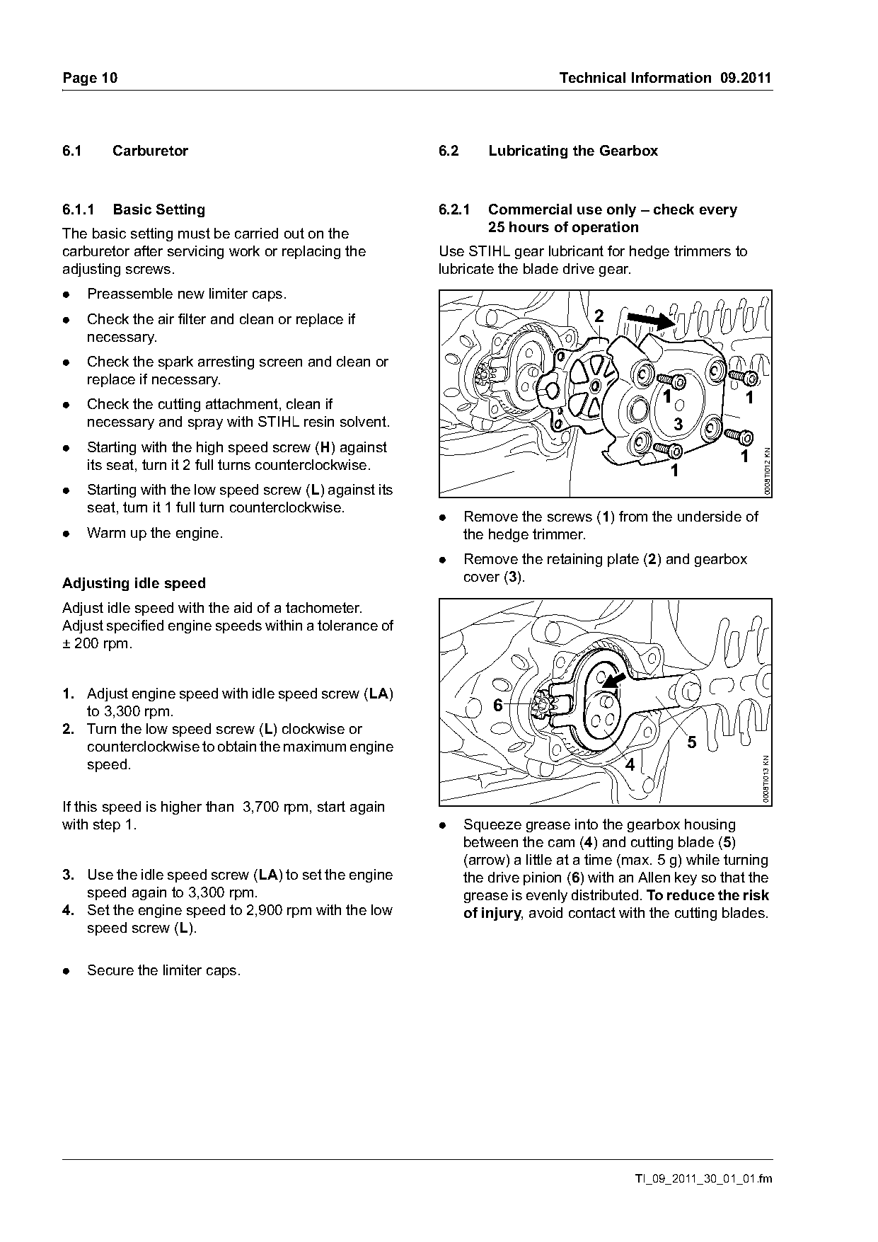
6.1.1     Basic Setting                                   6.2.1     Commercial use only – check every
The basic setting must be carried out on the                        25 hours of operation
carburetor after servicing work or replacing the          Use STIHL gear lubricant for hedge trimmers to
adjusting screws.                                         lubricate the blade drive gear.
.     Preassemble new limiter caps.
.     Check the air filter and clean or replace if                                   2
      necessary.
.     Check the spark arresting screen and clean or
      replace if necessary.
.     Check the cutting attachment, clean if                                                                  1
      necessary and spray with STIHL resin solvent.                                                3
.     Starting with the high speed screw (H) against
                                                                                                              1

                                                                                                                    0008TI012 KN
      its seat, turn it 2 full turns counterclockwise.                                            1
.     Starting with the low speed screw (L) against its
      seat, turn it 1 full turn counterclockwise.
                                                          .     Remove the screws (1) from the underside of
.     Warm up the engine.                                       the hedge trimmer.
                                                          .     Remove the retaining plate (2) and gearbox
Adjusting idle speed                                            cover (3).

Adjust idle speed with the aid of a tachometer.
Adjust specified engine speeds within a tolerance of
± 200 rpm.

1. Adjust engine speed with idle speed screw (LA)
   to 3,300 rpm.                                                    6
2. Turn the low speed screw (L) clockwise or
   counterclockwise to obtain the maximum engine                                                       5
   speed.                                                                                  4                      0008TI013 KN

If this speed is higher than 3,700 rpm, start again
with step 1.                                              .     Squeeze grease into the gearbox housing
                                                                between the cam (4) and cutting blade (5)
                                                                (arrow) a little at a time (max. 5 g) while turning
3. Use the idle speed screw (LA) to set the engine              the drive pinion (6) with an Allen key so that the
   speed again to 3,300 rpm.                                    grease is evenly distributed. To reduce the risk
4. Set the engine speed to 2,900 rpm with the low               of injury, avoid contact with the cutting blades.
   speed screw (L).

.     Secure the limiter caps.

                                                                                            TI_09_2011_30_01_01.fm
Page 11 of 12
Text of page 11 — search, copy, screen readers
Technical Information 09.2011                                                                                       Page 11

                                                                       6.3      Fuel System – Hose Barb Connectors
                          2                                            To guarantee the tightness of the fuel system:
                                                                       .     To avoid damaging hose barb connectors, pull
                                                                             off and push on fuel hoses in line with the
                                                                             connector by hand where possible – do not use
                                                    1                        sharp-edged pliers, screwdrivers, etc. and do
                                                                             not cut open fuel hoses with a knife or similar
                                       3                                     tools.
                                                   1                   .     Do not re-use fuel hoses after removal. Always

                                                        0008TI014 KN
                                       1                                     replace with new hoses – fuel hoses may be
                                                                             over-stretched during removal.
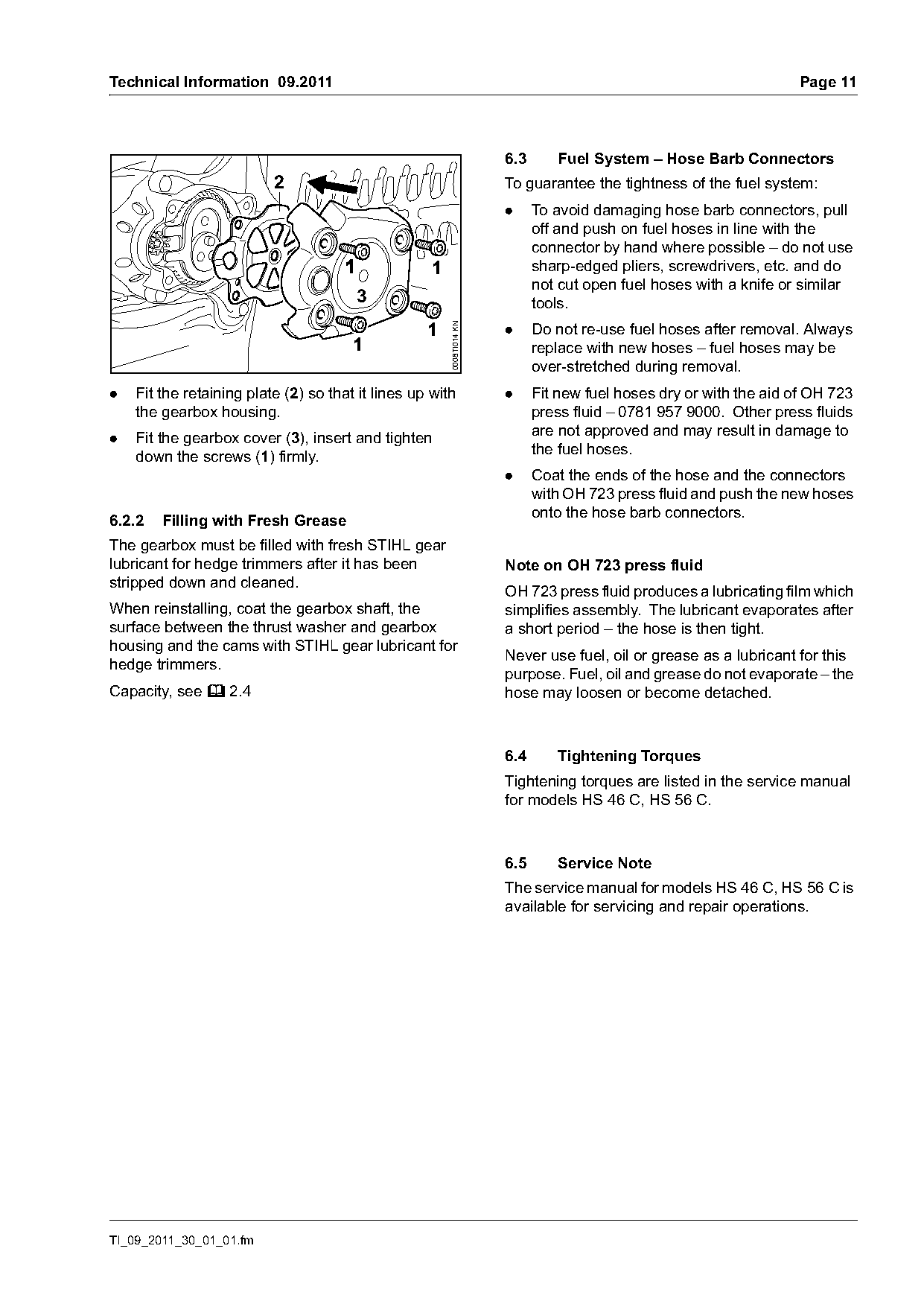
.   Fit the retaining plate (2) so that it lines up with               .     Fit new fuel hoses dry or with the aid of OH 723
    the gearbox housing.                                                     press fluid – 0781 957 9000. Other press fluids
                                                                             are not approved and may result in damage to
.   Fit the gearbox cover (3), insert and tighten
                                                                             the fuel hoses.
    down the screws (1) firmly.
                                                                       .     Coat the ends of the hose and the connectors
                                                                             with OH 723 press fluid and push the new hoses
                                                                             onto the hose barb connectors.
6.2.2   Filling with Fresh Grease
The gearbox must be filled with fresh STIHL gear
lubricant for hedge trimmers after it has been                         Note on OH 723 press fluid
stripped down and cleaned.
                                                                       OH 723 press fluid produces a lubricating film which
When reinstalling, coat the gearbox shaft, the                         simplifies assembly. The lubricant evaporates after
surface between the thrust washer and gearbox                          a short period – the hose is then tight.
housing and the cams with STIHL gear lubricant for
                                                                       Never use fuel, oil or grease as a lubricant for this
hedge trimmers.
                                                                       purpose. Fuel, oil and grease do not evaporate – the
Capacity, see b 2.4                                                    hose may loosen or become detached.

                                                                       6.4      Tightening Torques
                                                                       Tightening torques are listed in the service manual
                                                                       for models HS 46 C, HS 56 C.

                                                                       6.5      Service Note
                                                                       The service manual for models HS 46 C, HS 56 C is
                                                                       available for servicing and repair operations.

TI_09_2011_30_01_01.fm
Page 12 of 12
Text of page 12 — search, copy, screen readers
Page 12                                                                            Technical Information 09.2011

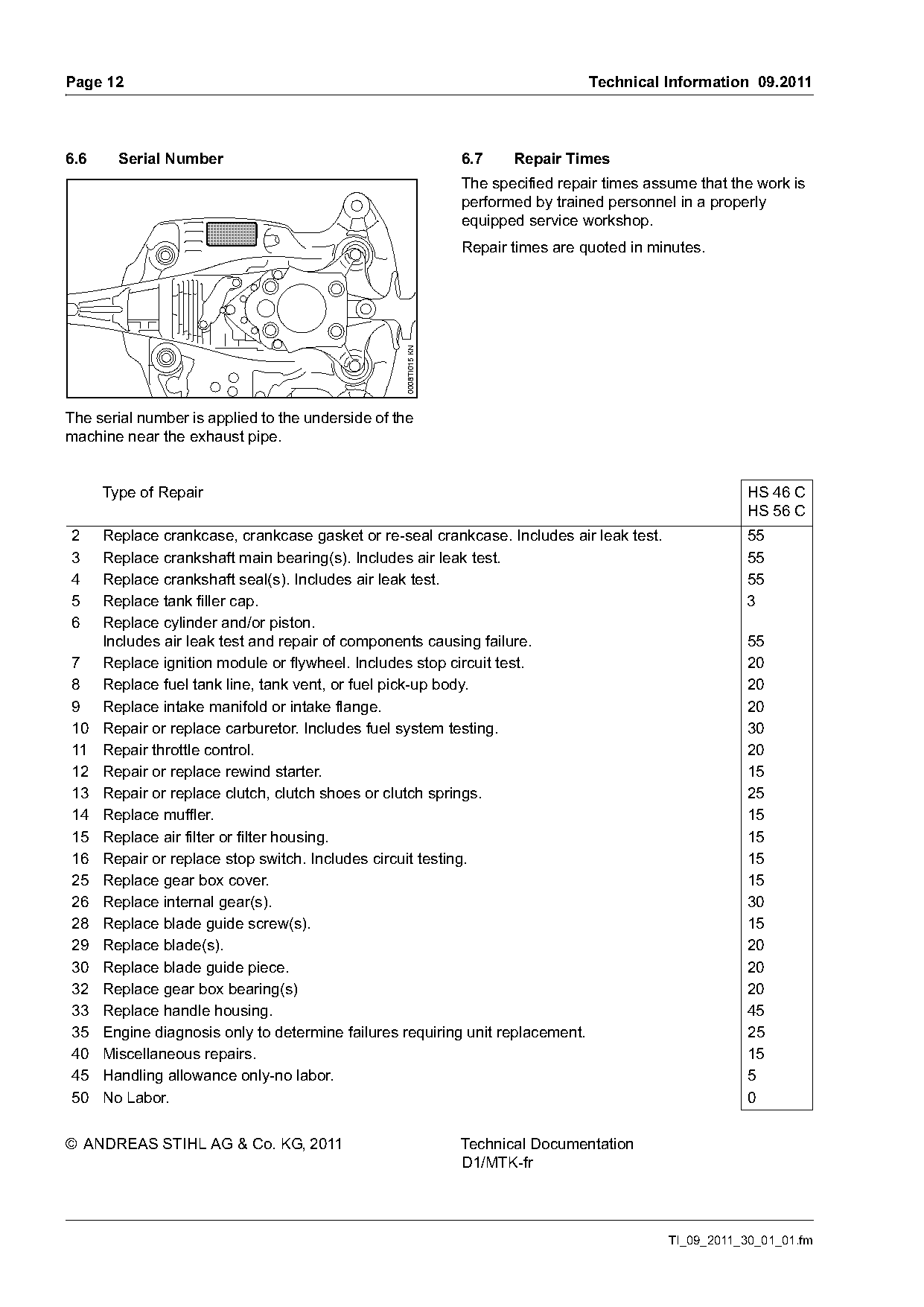
6.6     Serial Number                                            6.7    Repair Times
                                                                 The specified repair times assume that the work is
                                                                 performed by trained personnel in a properly
                                                                 equipped service workshop.
                                                                 Repair times are quoted in minutes.

                                                  0008TI015 KN
The serial number is applied to the underside of the
machine near the exhaust pipe.

      Type of Repair                                                                                       HS 46 C
                                                                                                           HS 56 C
2     Replace crankcase, crankcase gasket or re-seal crankcase. Includes air leak test.                   55
3     Replace crankshaft main bearing(s). Includes air leak test.                                         55
4     Replace crankshaft seal(s). Includes air leak test.                                                 55
5     Replace tank filler cap.                                                                            3
6     Replace cylinder and/or piston.
      Includes air leak test and repair of components causing failure.                                    55
7     Replace ignition module or flywheel. Includes stop circuit test.                                    20
8     Replace fuel tank line, tank vent, or fuel pick-up body.                                            20
9     Replace intake manifold or intake flange.                                                           20
10    Repair or replace carburetor. Includes fuel system testing.                                         30
11    Repair throttle control.                                                                            20
12    Repair or replace rewind starter.                                                                   15
13    Repair or replace clutch, clutch shoes or clutch springs.                                           25
14    Replace muffler.                                                                                    15
15    Replace air filter or filter housing.                                                               15
16    Repair or replace stop switch. Includes circuit testing.                                            15
25    Replace gear box cover.                                                                             15
26    Replace internal gear(s).                                                                           30
28    Replace blade guide screw(s).                                                                       15
29    Replace blade(s).                                                                                   20
30    Replace blade guide piece.                                                                          20
32    Replace gear box bearing(s)                                                                         20
33    Replace handle housing.                                                                             45
35    Engine diagnosis only to determine failures requiring unit replacement.                             25
40    Miscellaneous repairs.                                                                              15
45    Handling allowance only-no labor.                                                                   5
50    No Labor.                                                                                           0

© ANDREAS STIHL AG & Co. KG, 2011                                Technical Documentation
                                                                 D1/MTK-fr

                                                                                               TI_09_2011_30_01_01.fm
Most of these PDFs embed fonts with a shifted character map, so the text above was recovered rather than copied — read it as a faithful but imperfect transcription, and treat the page image above each block as the authority where the two disagree — the figures exist only there, because they are vector drawings that text extraction cannot keep.