Technical Information · issue 10 of 2011
Fuel tank, filler cap, shroud; Service information "Fuel tank, filler cap"; Throttle cable, tensioner, spacer flange; Ignition module; Fan housing; Drive shaft, flexible liner; Chapter "Fueling" in the Instruction Manual; Summary
IssueTI 10/2011
Part changes (7)
| Was | Becomes | What the bulletin says |
|---|---|---|
| 4180 350 0424 | 4180 350 0432 | 53 l), filler cap The previous fuel tanks 4180 350 0424 and 4180 350 0425 are being replaced by the version 4180 350 0432. |
| 0000 350 0535 | 0000 350 0517 | At the same time, the previous toolless filler cap 0000 350 0535 is being replaced by the threaded filler cap 0000 350 0517. |
| 4180 080 1604 | 4180 080 1605 | 2 Shroud, pictogram The previous shroud 4180 080 1604 with pictogram 0000 967 3605 is being replaced by the shroud 4180 080 1605. |
| 4180 182 7600 | 4180 182 7601 | – Pictogram 0000 967 7222 Simultaneously, the previous tensioner 4180 182 7600 will be replaced by the version After all service work on the machine, always check 4180 182 7601. |
| 4180 400 1300 | 4180 400 1308 | 3 Permissible cylinder/washer/ignition module combinations The previous ignition module 4180 400 1300 is being replaced by the version 4180 400 1308. |
| 4137 710 3202 | 4137 711 3202 | Only for FS 100 RX, FS 110 X and FS 110 RX The previous lightweight drive shaft 4137 710 3202 and flexible liner 4134 711 7301 are being replaced by the flexible drive shaft 4137 711 3202 and the flexible liner 4137 711 7300. |
| 4180 080 1801 | 4180 080 1809 | 246TI009 KN In older machines with the previously lightweight drive shaft 4137 710 3202 and flexible liner The previous fan housing 4180 080 1801 with rivets 4134 711 7301, during servicing, the new flexible 9416 868 6510 is being replaced by the version drive shaft must always be replaced together |
Full text
Page 1 of 8
Text of page 1 — search, copy, screen readers
STIH)

Technical Information                                      10.2011

  Brushcutter STIHL FS 90, 100, 110, 130               – Series 4180
  KombiEngine STIHL KM 90, 100, 110, 130               – Series 4180
  Edger FC 90, 95, 100, 110                            – Series 4180
  Pole pruner STIHL HT 100, 101, 130, 131              – Series 4182
  Hedge trimmer STIHL HL 90 K, 95, 95 K, 100, 100 K    – Series 4280

  Contents
  1.    Fuel tank, filler cap, shroud
  2.    Service information "Fuel tank, filler cap"
  3.    Throttle cable, tensioner, spacer flange
  4.    Ignition module
  5.    Fan housing
  6.    Drive shaft, flexible liner
  7.    Chapter "Fueling" in the Instruction Manual
  8.    Summary

  1.       Fuel tank, filler cap, shroud

  1.1      Fuel tank 18 oz. (0.53 l), filler cap
  The previous fuel tanks 4180 350 0424 and
  4180 350 0425 are being replaced by the version
  4180 350 0432.
  At the same time, the previous toolless filler cap
  0000 350 0535 is being replaced by the threaded
  filler cap 0000 350 0517.

  TI_10_2011_30_01_01.fm                                         englisch / English
Page 2 of 8
Text of page 2 — search, copy, screen readers
Page 2                                                                              Technical Information 10.2011

                                                                1.2     Shroud, pictogram
                                                                The previous shroud 4180 080 1604 with pictogram
                                                                0000 967 3605 is being replaced by the shroud
                                                                4180 080 1605. The new shroud includes the
                                                                previous pictogram 0000 967 3605, the new
                                                                pictograms 0000 967 7222 and 0000 967 4055.

                                                                1.2.1   Spare parts
                                                                Only the new shroud is still available as a spare part.

                                                  249TI082 KN
                                                                The new shroud includes the previous pictogram
                                                                0000 967 3605 (toolless filler cap), the new
                                                                pictogram 0000 967 7222 (threaded filler cap) and
Left:    Previous fuel tank 4180 350 0424 or                    pictogram 0000 967 4055 (spark arresting screen).
         4180 350 0425 and toolless filler cap                  The previous shroud will no longer be available from
         0000 350 0535                                          the factory.
Right:   New fuel tank 4180 350 0431 and
         threaded filler cap 0000 350 0517                      1.2.2   Service notes
                                                                If a new shroud is installed while the machine is
1.1.1    Warning pictogram filler cap
                                                                being serviced, the appropriate pictogram for the
At the same time, the previous pictogram                        filler cap must be attached to the shroud, depending
0000 967 3605 is being replaced by the version                  on the fuel tank in use.
0000 967 7222.

1.1.2    Spare parts
As a replacement part, the new fuel tank includes
the threaded filler cap and the pictogram
0000 967 7222. Thus the new fuel tank can also be
used with older machines.
The previous fuel tanks will no longer be available
from the factory. The previous toolless filler cap
0000 350 0535 and the previous pictogram
0000 967 3605 remain available for older machines
with the previous fuel tank.

1.1.3    Service notes
If the new fuel tank with the threaded filler cap is
installed while the machine is being serviced, the
included pictogram 0000 967 7222 must be
attached to the shroud.
After all service work on the machine, always check
the condition of the warning pictograms. Add or
replace warning pictograms if necessary.

                                                                                                TI_10_2011_30_01_01.fm
Page 3 of 8
Text of page 3 — search, copy, screen readers
Technical Information 10.2011                                                                                    Page 3

Tank filler cap/pictogram combinations                              3.      Throttle cable, tensioner, spacer
                                                                            flange

                                                                    3.1     Throttle cable, tensioner
                                                                    The previous throttle cables are being replaced by
                                                                    the new versions with an extended plastic tube for
                                                                    the wire core.

                                                      249TI089 KN
–    Toolless filler cap 0000 350 0535
–    Pictogram 0000 967 3605

                                                                                                                       249TI085 KN
                                                                    Top:    Previous throttle cable with "exposed"
                                                                            wire core
                                                                    Bottom: New throttle cable with extended,
                                                                            flexible plastic tube for the wire core
                                                  249TI090 KN

                                                                    With the new throttle cables, the wire cores are also
                                                                    routed through a plastic tube in the vicinity of the
                                                                    tensioner. For this, the plastic tube in the Bowden
–    Threaded filler cap 0000 350 0517                              cable is extended.
–    Pictogram 0000 967 7222                                        Simultaneously, the previous tensioner
                                                                    4180 182 7600 will be replaced by the version
After all service work on the machine, always check                 4180 182 7601. The new tensioner is characterized
the condition of the warning pictograms. Add or                     by the routing of the throttle cable.
replace warning pictograms if necessary.

2.      Service information "Fuel tank,
        filler cap"
If a previous fuel tank and toolless filler cap is
replaced by the new version fuel tank and threaded
filler cap while a machine is being serviced, always
show the customer how to use the new filler cap.
If necessary, the description under point b 7 can
be printed out and given to the customer. This will
then replace the corresponding sections of the
chapter "Fueling" in the previous Instruction
Manual.

TI_10_2011_30_01_01.fm
Page 4 of 8
Text of page 4 — search, copy, screen readers
Page 4                                                                                  Technical Information 10.2011

3.1.1    Characteristics for differentiating                       3.2      Spacer flange
         between tensioners                                        Parallel to the new throttle cables, the gap for
                                                                   routing of the throttle cable has been enlarged on
                                                                   spacer flange 4180 120 2303. The part number of
                                                                   the spacer flange remains unchanged. The new
                                                                   spacer flange can also be used with older machines.

                                                                   Service note for the spacer flange

         4180 182 7600          4180 182 7601                                                                   a
                                                     249TI086 KN

Left:     previous version 4180 182 7600
Right:    new version 4180 182 7601

The tensioners can be identified according to these
markings:
–   Part number on the part
–   Routing of the throttle cable at the outlet of the
                                                                                                               b
    new tensioner (arrow)

3.1.2    Spare parts/service notes

                                                                                                                        249TI087 KN
When supplied as spare parts, the new throttle
cables are supplied with the new tensioner. Thus the
new throttle cables can also be used with older                    The dimension (b) in the gap is required for routing
machines.                                                          the throttle cable with the longer plastic tube.
New throttle cables must always be paired with a                   .     Check gap width (a) before installing a new
new tensioner.                                                           throttle cable
Previous throttle cables can be used both with the                 If the dimension (a) is between 0.095 and 0.102 in.
previous or new tensioners.                                        (2.4 and 2.6 mm), then:
The previous tensioner 4180 182 7600 can only be                   .     Rework the part – widen the gap so that the
combined with the previous throttle cables.                              width (b) is between 0.106 to 0.118 in. (2.7 and
For replaceability in previous machine versions,                         3.0 mm)
reworking of the spacer flange may be required as                  If the dimension is between 0.106 to 0.118 in.
needed, see b 3.2.                                                 (2.7 and 3.0 mm), no rework is necessary.

                                                                                                    TI_10_2011_30_01_01.fm
Page 5 of 8
Text of page 5 — search, copy, screen readers
Technical Information 10.2011                                                                               Page 5

4.      Ignition module                                          4.3    Permissible cylinder/washer/ignition
                                                                        module combinations
The previous ignition module 4180 400 1300 is
being replaced by the version 4180 400 1308.

4.1     Spare parts
From now on, only the new ignition module will be
available as a spare part. The new ignition module
can also be used with older machines. The previous
ignition module will no longer be available from the
factory.

4.2     In the event of service, the following
        combinations of ignition
        module/cylinder are permissible:
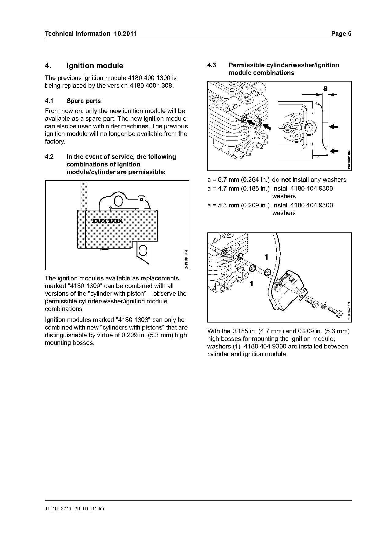
                                                                 a = 6.7 mm (0.264 in.) do not install any washers
                                                                 a = 4.7 mm (0.185 in.) Install 4180 404 9300
                                                                                        washers
                                                                 a = 5.3 mm (0.209 in.) Install 4180 404 9300
                                                                                        washers
                                                   249TI091 KN


The ignition modules available as replacements
marked "4180 1309" can be combined with all                                    1
versions of the "cylinder with piston" – observe the
permissible cylinder/washer/ignition module

                                                                                                                     249TI062 KN
combinations
Ignition modules marked "4180 1303" can only be
combined with new "cylinders with pistons" that are
                                                                 With the 0.185 in. (4.7 mm) and 0.209 in. (5.3 mm)
distinguishable by virtue of 0.209 in. (5.3 mm) high
                                                                 high bosses for mounting the ignition module,
mounting bosses.
                                                                 washers (1) 4180 404 9300 are installed between
                                                                 cylinder and ignition module.

TI_10_2011_30_01_01.fm
Page 6 of 8
Text of page 6 — search, copy, screen readers
Page 6                                                                               Technical Information 10.2011

5.       Fan housing                                              6.     Drive shaft, flexible liner
Only for machines with a polymer fan housing.                     Only for FS 100 RX, FS 110 X and FS 110 RX
                                                                  The previous lightweight drive shaft 4137 710 3202
                                                                  and flexible liner 4134 711 7301 are being replaced
                                                                  by the flexible drive shaft 4137 711 3202 and the
                                                                  flexible liner 4137 711 7300.

                                                                  Spare parts/service notes
                                                                  Only the new flexible drive shaft 4137 711 3202 and
                                                                  the new flexible liner 4137 711 7300 are supplied as
                                                                  spare parts.
                                                    246TI009 KN   In older machines with the previously lightweight
                                                                  drive shaft 4137 710 3202 and flexible liner
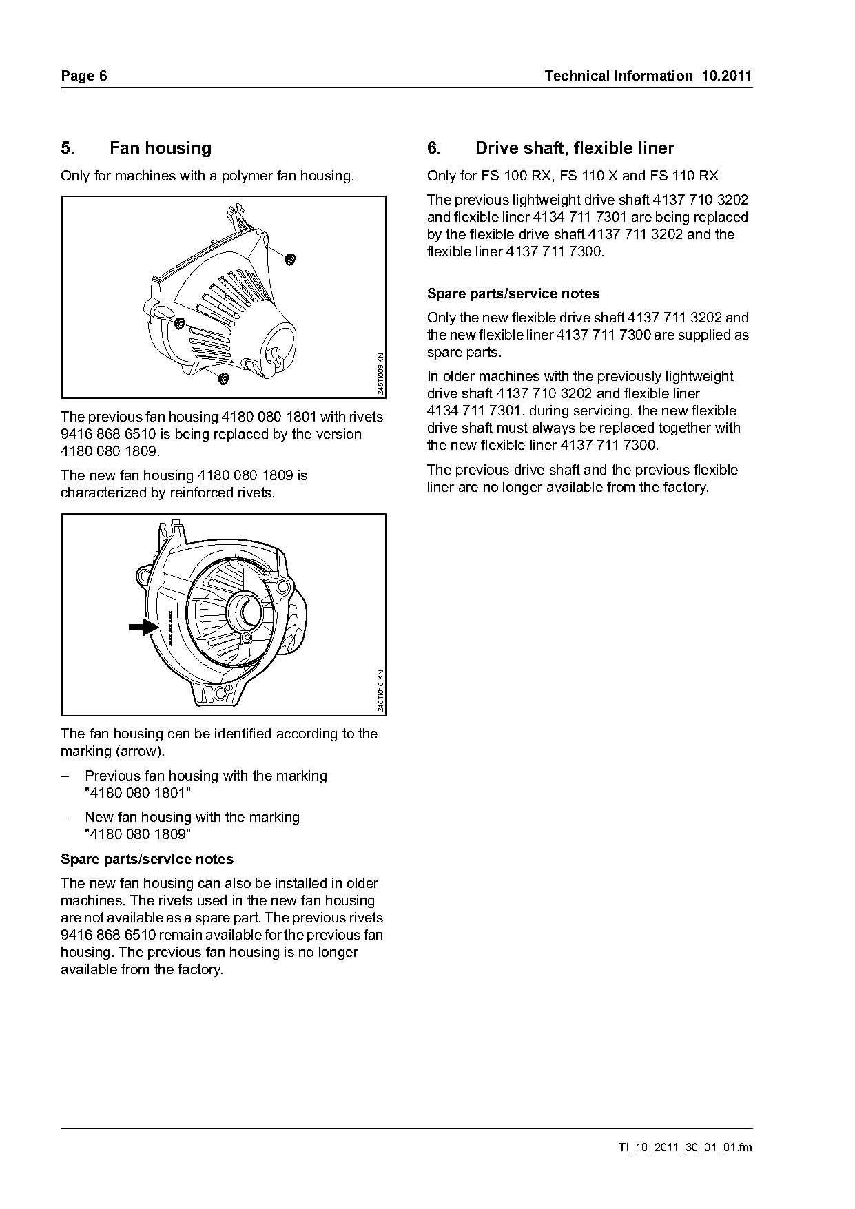
The previous fan housing 4180 080 1801 with rivets                4134 711 7301, during servicing, the new flexible
9416 868 6510 is being replaced by the version                    drive shaft must always be replaced together with
4180 080 1809.                                                    the new flexible liner 4137 711 7300.

The new fan housing 4180 080 1809 is                              The previous drive shaft and the previous flexible
characterized by reinforced rivets.                               liner are no longer available from the factory.
                                                    246TI010 KN

The fan housing can be identified according to the
marking (arrow).
–    Previous fan housing with the marking
     "4180 080 1801"
–    New fan housing with the marking
     "4180 080 1809"
Spare parts/service notes
The new fan housing can also be installed in older
machines. The rivets used in the new fan housing
are not available as a spare part. The previous rivets
9416 868 6510 remain available for the previous fan
housing. The previous fan housing is no longer
available from the factory.

                                                                                                TI_10_2011_30_01_01.fm
Page 7 of 8
Text of page 7 — search, copy, screen readers
Technical Information 10.2011                                        Page 7

7.      Chapter "Fueling" in the
        Instruction Manual
The following sections replace the corresponding
sections in the chapter "Fueling" in the Instruction
Manual.

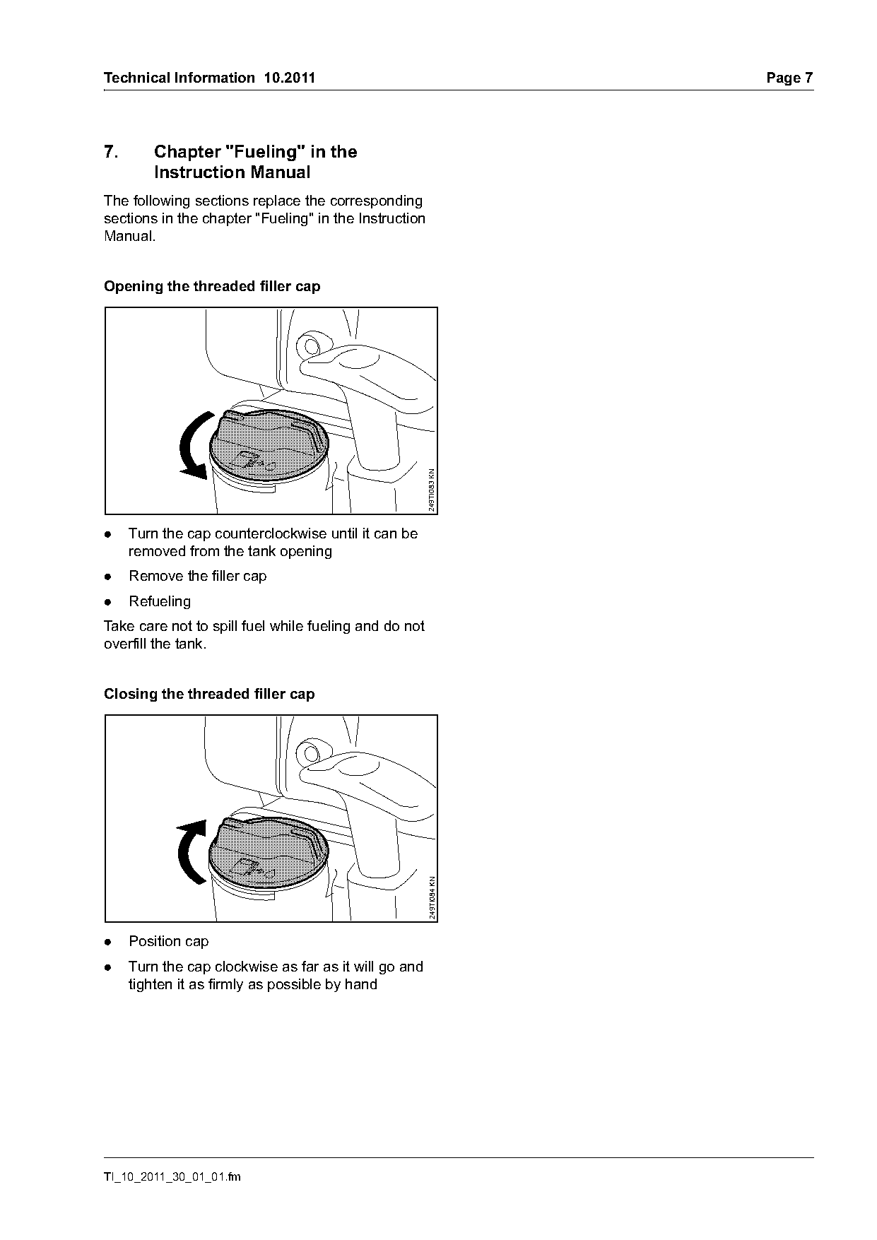
Opening the threaded filler cap

                                                       249TI083 KN

.    Turn the cap counterclockwise until it can be
     removed from the tank opening
.    Remove the filler cap
.    Refueling
Take care not to spill fuel while fueling and do not
overfill the tank.

Closing the threaded filler cap
                                                       249TI084 KN

.    Position cap
.    Turn the cap clockwise as far as it will go and
     tighten it as firmly as possible by hand

TI_10_2011_30_01_01.fm
Page 8 of 8
Text of page 8 — search, copy, screen readers
Page 8                                                                       Technical Information 10.2011

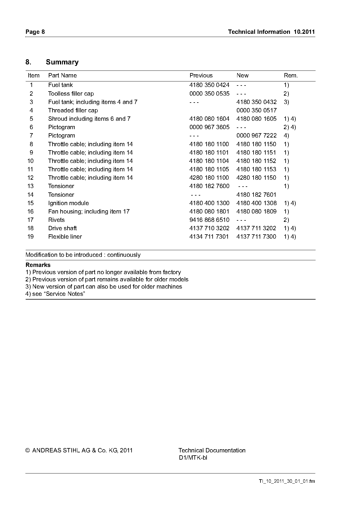
8.       Summary
Item     Part Name                                               Previous        New             Rem.
 1       Fuel tank                                               4180 350 0424   ---             1)
 2       Toolless filler cap                                     0000 350 0535   ---             2)
 3       Fuel tank; including items 4 and 7                      ---             4180 350 0432   3)
 4       Threaded filler cap                                                     0000 350 0517
 5       Shroud including items 6 and 7                          4180 080 1604   4180 080 1605   1) 4)
 6       Pictogram                                               0000 967 3605   ---             2) 4)
 7       Pictogram                                               ---             0000 967 7222   4)
 8       Throttle cable; including item 14                       4180 180 1100   4180 180 1150   1)
 9       Throttle cable; including item 14                       4180 180 1101   4180 180 1151   1)
10       Throttle cable; including item 14                       4180 180 1104   4180 180 1152   1)
11       Throttle cable; including item 14                       4180 180 1105   4180 180 1153   1)
12       Throttle cable; including item 14                       4280 180 1100   4280 180 1150   1)
13       Tensioner                                               4180 182 7600    ---            1)
14       Tensioner                                                ---            4180 182 7601
15       Ignition module                                         4180 400 1300   4180 400 1308   1) 4)
16       Fan housing; including item 17                          4180 080 1801   4180 080 1809   1)
17       Rivets                                                  9416 868 6510   ---             2)
18       Drive shaft                                             4137 710 3202   4137 711 3202   1) 4)
19       Flexible liner                                          4134 711 7301   4137 711 7300   1) 4)

Modification to be introduced : continuously
Remarks
1) Previous version of part no longer available from factory
2) Previous version of part remains available for older models
3) New version of part can also be used for older machines
4) see “Service Notes”

© ANDREAS STIHL AG & Co. KG, 2011                         Technical Documentation
                                                          D1/MTK-bl

                                                                                        TI_10_2011_30_01_01.fm
Most of these PDFs embed fonts with a shifted character map, so the text above was recovered rather than copied — read it as a faithful but imperfect transcription, and treat the page image above each block as the authority where the two disagree — the figures exist only there, because they are vector drawings that text extraction cannot keep.