Technical Information · issue 11 of 2011
New STIHL BR 350, BR 430 Backpack Blowers
IssueTI 11/2011
Full text
Page 1 of 9
Text of page 1 — search, copy, screen readers
STIH)

Technical Information                                       11.2011

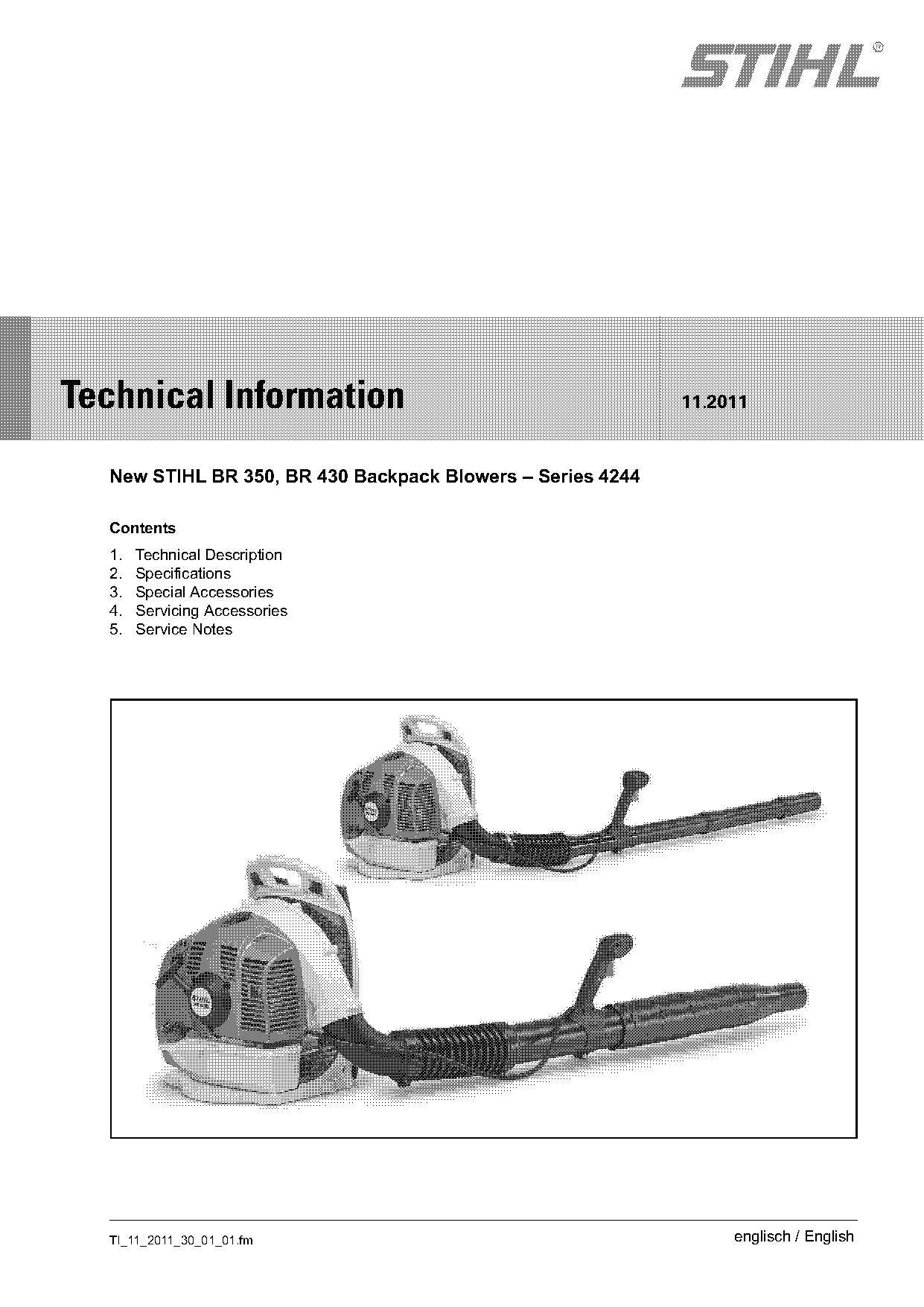
  New STIHL BR 350, BR 430 Backpack Blowers – Series 4244

  Contents
  1.   Technical Description
  2.   Specifications
  3.   Special Accessories
  4.   Servicing Accessories
  5.   Service Notes

  TI_11_2011_30_01_01.fm                                         englisch / English
Page 2 of 9
Text of page 2 — search, copy, screen readers
Page 2                                                                        Technical Information 11.2011

The new BR 350 backpack blower is a reasonably           1.      Technical Description
priced and reliable entry-level model in the
professional sector.                                     1.1     2-Cycle Engine with Stratified
The new BR 430 backpack blower offers high power                 Scavenging
and convenience.                                         The engine installed in the new blowers uses our
A special feature of the new blowers is the simplified   proven 2-cycle technology for fuel-efficient and low
starting procedure – the choke knob and the manual       emission operation.
fuel pump need only be operated once for each
start.
                                                         Method of operation
The new blowers are powered by the particularly
                                                         A buffer of fuel-free air separates the fresh mixture
fuel-efficient, low emission STIHL 2-cycle engine,
                                                         and exhaust gas. The air buffer flows into the
which complies with EU II and EPA III.
                                                         cylinder ahead of the fresh mixture.
                                                         At the start of the scavenging and intake stroke,
Target groups                                            fuel-free air flows into the combustion chamber first
–   Landscapers                                          and pushes the exhaust gas into the exhaust port.
                                                         The air buffer prevents the subsequent charge of
–   Municipalities                                       fresh mixture escaping through the exhaust port.
–   Janitorial services                                  The reduction in scavenging loses results in less
–   Private users                                        emissions and a lower fuel consumption.

Applications                                             1.2     Air Filter
–   Garden and landscape care                            Compared to the BR 380 and BR 420, the filter area
–   Sports facilities                                    of the new BR 350 and BR 430 blowers is 50%
                                                         larger.
–   Parks
                                                         The new blowers therefore have a longer filter life.

                                                         1.3     Blowing Attachment
                                                         The blowing attachment must be properly mounted
                                                         before the machine is operated – see instruction
                                                         manual.

                                                                                        TI_11_2011_30_01_01.fm
Page 3 of 9
Text of page 3 — search, copy, screen readers
Technical Information 11.2011                                                                                           Page 3

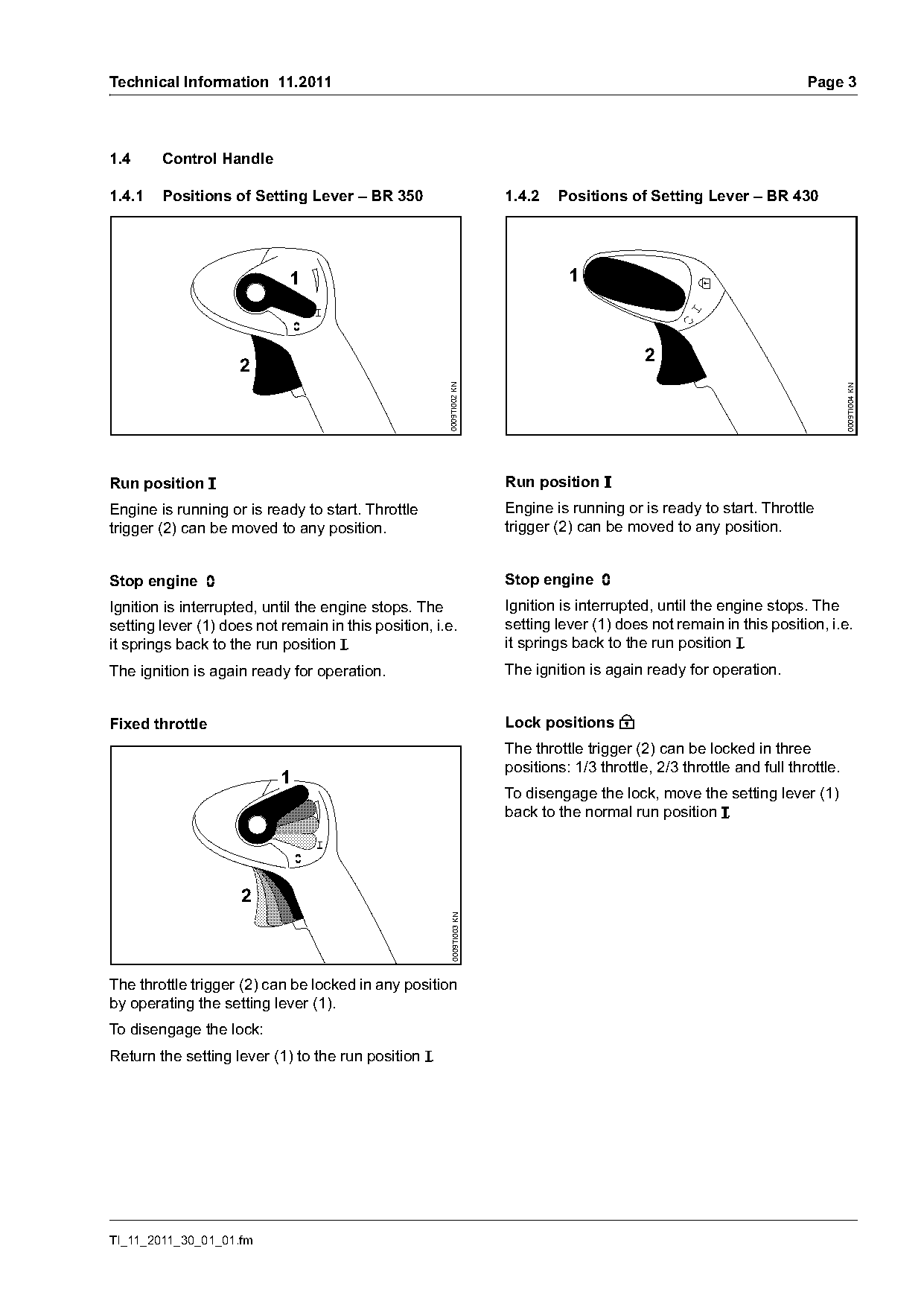
1.4     Control Handle

1.4.1   Positions of Setting Lever – BR 350                           1.4.2   Positions of Setting Lever – BR 430

                            1                                                   1

                                                                                             2
                     2

                                                      0009TI002 KN

                                                                                                                                 0009TI004 KN
Run position F                                                        Run position F
Engine is running or is ready to start. Throttle                      Engine is running or is ready to start. Throttle
trigger (2) can be moved to any position.                             trigger (2) can be moved to any position.

Stop engine †                                                         Stop engine †
Ignition is interrupted, until the engine stops. The                  Ignition is interrupted, until the engine stops. The
setting lever (1) does not remain in this position, i.e.              setting lever (1) does not remain in this position, i.e.
it springs back to the run position F.                                it springs back to the run position F.
The ignition is again ready for operation.                            The ignition is again ready for operation.

Fixed throttle                                                        Lock positions C
                                                                      The throttle trigger (2) can be locked in three
                                                                      positions: 1/3 throttle, 2/3 throttle and full throttle.
                           1
                                                                      To disengage the lock, move the setting lever (1)
                                                                      back to the normal run position F.

                     2
                                                       0009TI003 KN

The throttle trigger (2) can be locked in any position
by operating the setting lever (1).
To disengage the lock:
Return the setting lever (1) to the run position F.

TI_11_2011_30_01_01.fm
Page 4 of 9
Text of page 4 — search, copy, screen readers
Page 4                                                                                  Technical Information 11.2011

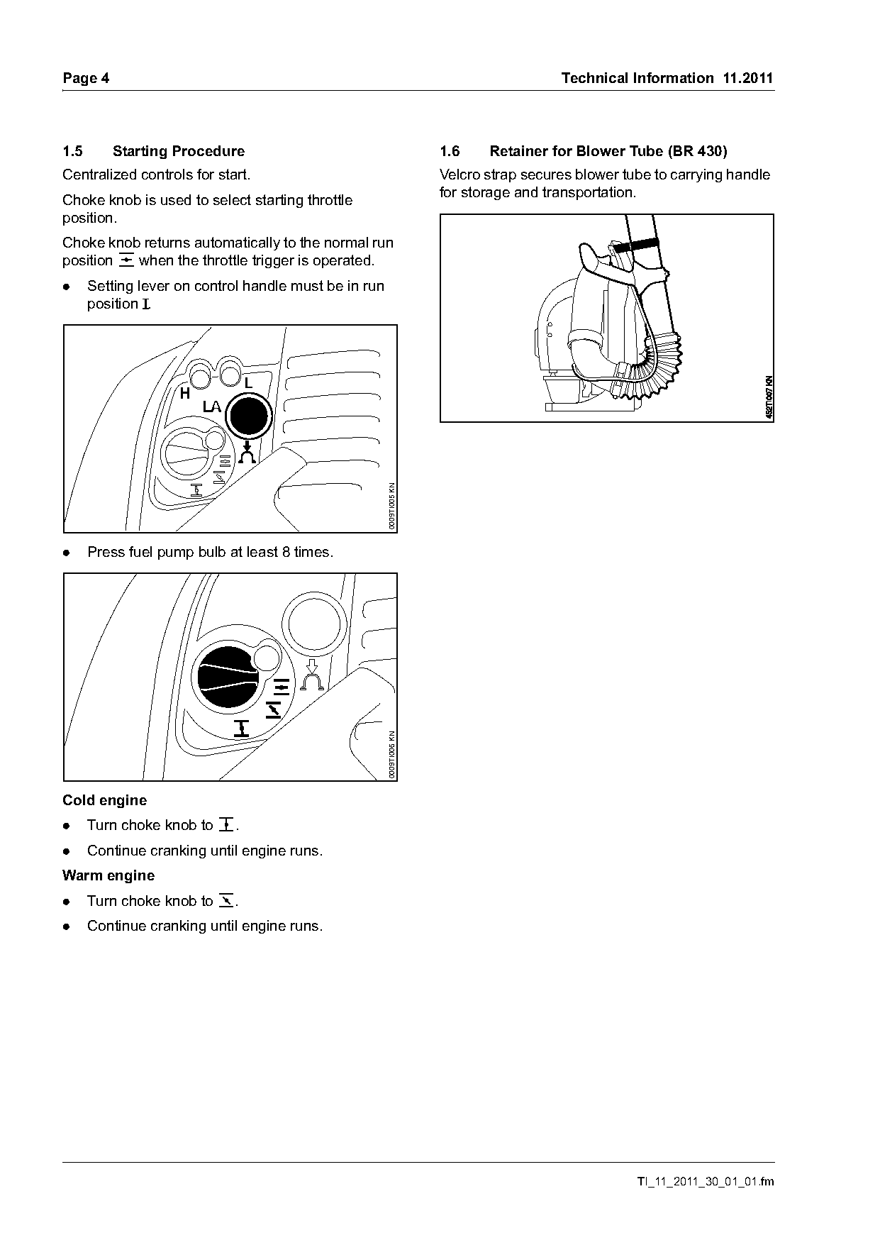
1.5      Starting Procedure                                           1.6    Retainer for Blower Tube (BR 430)
Centralized controls for start.                                       Velcro strap secures blower tube to carrying handle
                                                                      for storage and transportation.
Choke knob is used to select starting throttle
position.
Choke knob returns automatically to the normal run
position e when the throttle trigger is operated.
.     Setting lever on control handle must be in run
      position F.

                                                       0009TI005 KN

.     Press fuel pump bulb at least 8 times.
                                                       0009TI006 KN

Cold engine
.     Turn choke knob to c.
.     Continue cranking until engine runs.
Warm engine
.     Turn choke knob to o.
.     Continue cranking until engine runs.

                                                                                                    TI_11_2011_30_01_01.fm
Page 5 of 9
Text of page 5 — search, copy, screen readers
Technical Information 11.2011                                                                       Page 5

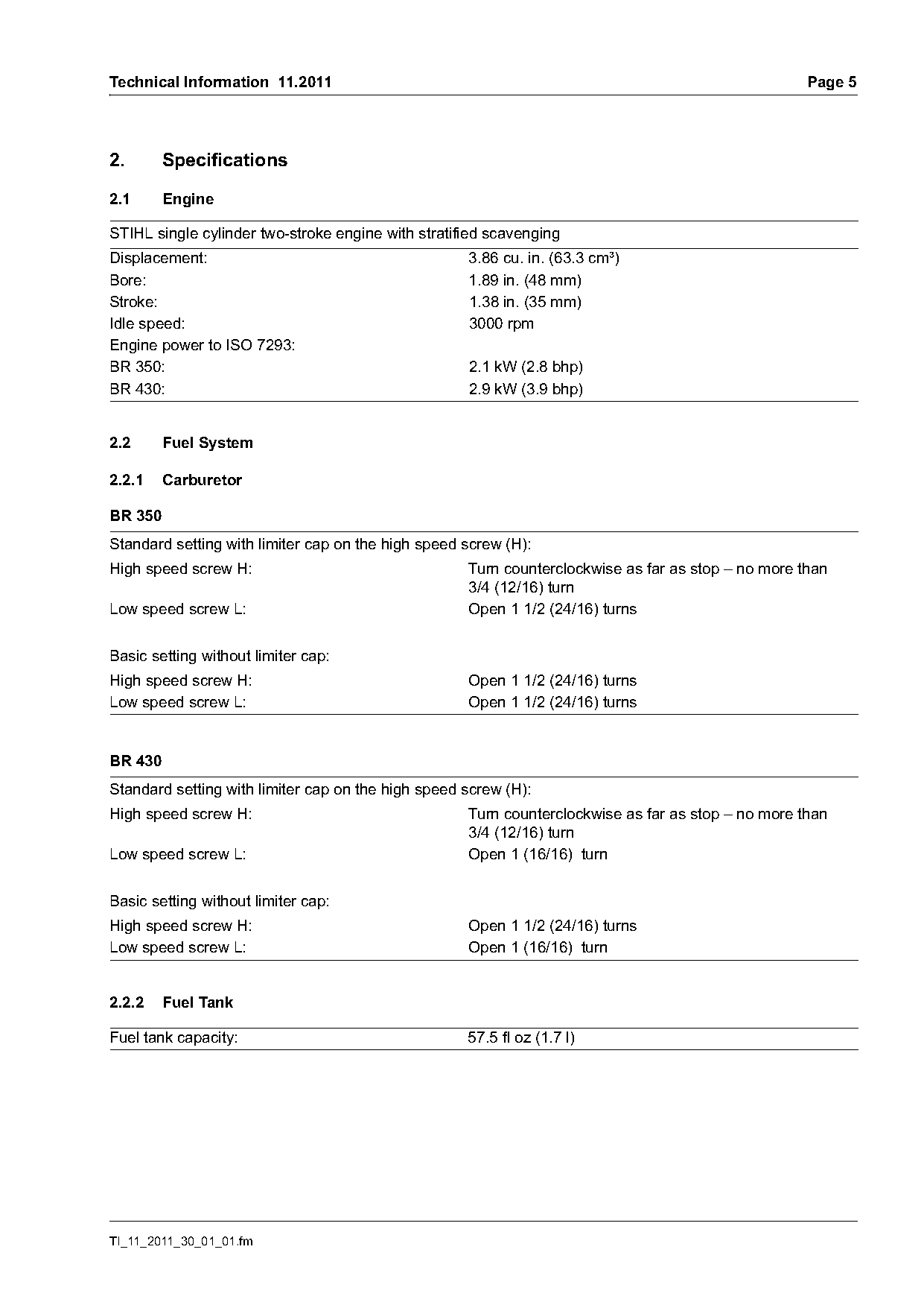
2.       Specifications

2.1      Engine

STIHL single cylinder two-stroke engine with stratified scavenging
Displacement:                                       3.86 cu. in. (63.3 cm³)
Bore:                                               1.89 in. (48 mm)
Stroke:                                             1.38 in. (35 mm)
Idle speed:                                         3000 rpm
Engine power to ISO 7293:
BR 350:                                             2.1 kW (2.8 bhp)
BR 430:                                             2.9 kW (3.9 bhp)

2.2      Fuel System

2.2.1    Carburetor

BR 350
Standard setting with limiter cap on the high speed screw (H):
High speed screw H:                                 Turn counterclockwise as far as stop – no more than
                                                    3/4 (12/16) turn
Low speed screw L:                                  Open 1 1/2 (24/16) turns

Basic setting without limiter cap:
High speed screw H:                                 Open 1 1/2 (24/16) turns
Low speed screw L:                                  Open 1 1/2 (24/16) turns

BR 430
Standard setting with limiter cap on the high speed screw (H):
High speed screw H:                                 Turn counterclockwise as far as stop – no more than
                                                    3/4 (12/16) turn
Low speed screw L:                                  Open 1 (16/16) turn

Basic setting without limiter cap:
High speed screw H:                                 Open 1 1/2 (24/16) turns
Low speed screw L:                                  Open 1 (16/16) turn

2.2.2    Fuel Tank

Fuel tank capacity:                                 57.5 fl oz (1.7 l)

TI_11_2011_30_01_01.fm
Page 6 of 9
Text of page 6 — search, copy, screen readers
Page 6                                                                     Technical Information 11.2011

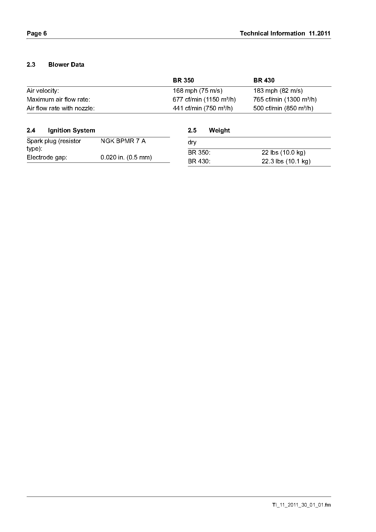
2.3      Blower Data

                                                  BR 350                       BR 430
Air velocity:                                     168 mph (75 m/s)             183 mph (82 m/s)
Maximum air flow rate:                            677 cf/min (1150 m³/h)       765 cf/min (1300 m³/h)
Air flow rate with nozzle:                        441 cf/min (750 m³/h)        500 cf/min (850 m³/h)

2.4      Ignition System                               2.5    Weight
Spark plug (resistor         NGK BPMR 7 A              dry
type):
                                                       BR 350:                   22 lbs (10.0 kg)
Electrode gap:               0.020 in. (0.5 mm)
                                                       BR 430:                   22.3 lbs (10.1 kg)

                                                                                     TI_11_2011_30_01_01.fm
Page 7 of 9
Text of page 7 — search, copy, screen readers
Technical Information 11.2011                                                                      Page 7

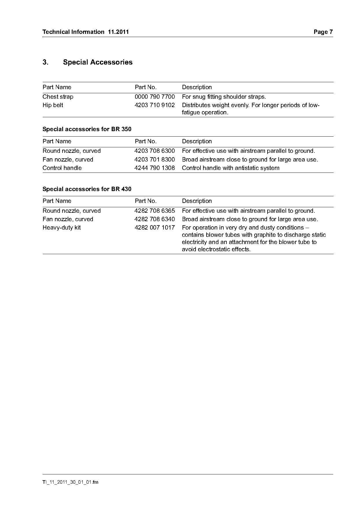
3.      Special Accessories

Part Name                        Part No.        Description
Chest strap                      0000 790 7700   For snug fitting shoulder straps.
Hip belt                         4203 710 9102   Distributes weight evenly. For longer periods of low-
                                                 fatigue operation.

Special accessories for BR 350

Part Name                        Part No.        Description
Round nozzle, curved             4203 708 6300   For effective use with airstream parallel to ground.
Fan nozzle, curved               4203 701 8300   Broad airstream close to ground for large area use.
Control handle                   4244 790 1308   Control handle with antistatic system

Special accessories for BR 430

Part Name                        Part No.        Description
Round nozzle, curved             4282 708 6365   For effective use with airstream parallel to ground.
Fan nozzle, curved               4282 708 6340   Broad airstream close to ground for large area use.
Heavy-duty kit                   4282 007 1017   For operation in very dry and dusty conditions –
                                                 contains blower tubes with graphite to discharge static
                                                 electricity and an attachment for the blower tube to
                                                 avoid electrostatic effects.

TI_11_2011_30_01_01.fm
Page 8 of 9
Text of page 8 — search, copy, screen readers
Page 8                                                                       Technical Information 11.2011

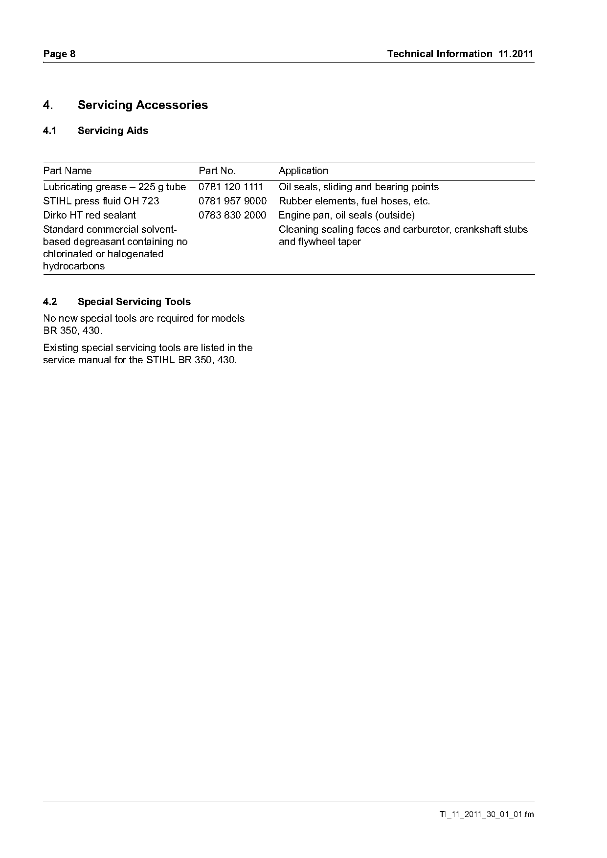
4.       Servicing Accessories

4.1      Servicing Aids

Part Name                            Part No.        Application
Lubricating grease – 225 g tube      0781 120 1111   Oil seals, sliding and bearing points
STIHL press fluid OH 723             0781 957 9000   Rubber elements, fuel hoses, etc.
Dirko HT red sealant                 0783 830 2000   Engine pan, oil seals (outside)
Standard commercial solvent-                         Cleaning sealing faces and carburetor, crankshaft stubs
based degreasant containing no                       and flywheel taper
chlorinated or halogenated
hydrocarbons

4.2      Special Servicing Tools
No new special tools are required for models
BR 350, 430.
Existing special servicing tools are listed in the
service manual for the STIHL BR 350, 430.

                                                                                        TI_11_2011_30_01_01.fm
Page 9 of 9
Text of page 9 — search, copy, screen readers
Technical Information 11.2011                                                                                    Page 9

5.      Service Notes                                                 5.4      Repair Times

If the machine is started in the course of repairs, it is             The specified repair times assume that the work is
essential to observe all country-specific safety                      performed by trained personnel in a properly
regulations and the safety precautions in the                         equipped service workshop.
instruction manual.                                                   Repair times are quoted in minutes.
                                                                            Repair procedure                     BR 350
                                                                                                                 BR 430
5.1     Service Manual
                                                                      2  Replace crankcase, crankcase
The STIHL BR 350, 430 service manual is available                        gasket or re-seal crankcase.
for servicing and repairs.                                               Includes air leak test.                   100
                                                                      3 Replace crankshaft main bearing(s).
                                                                         Includes air leak test.                   100
5.2     Tightening Torques                                            4 Replace crankshaft seal(s). Includes
Tightening torques are listed in the service manual                      air leak test.                            60
for the STIHL BR 350, 430.                                            5 Replace tank filler cap.                    3
                                                                      6 Replace cylinder and/or piston.
                                                                         Includes air leak test and diagnosis
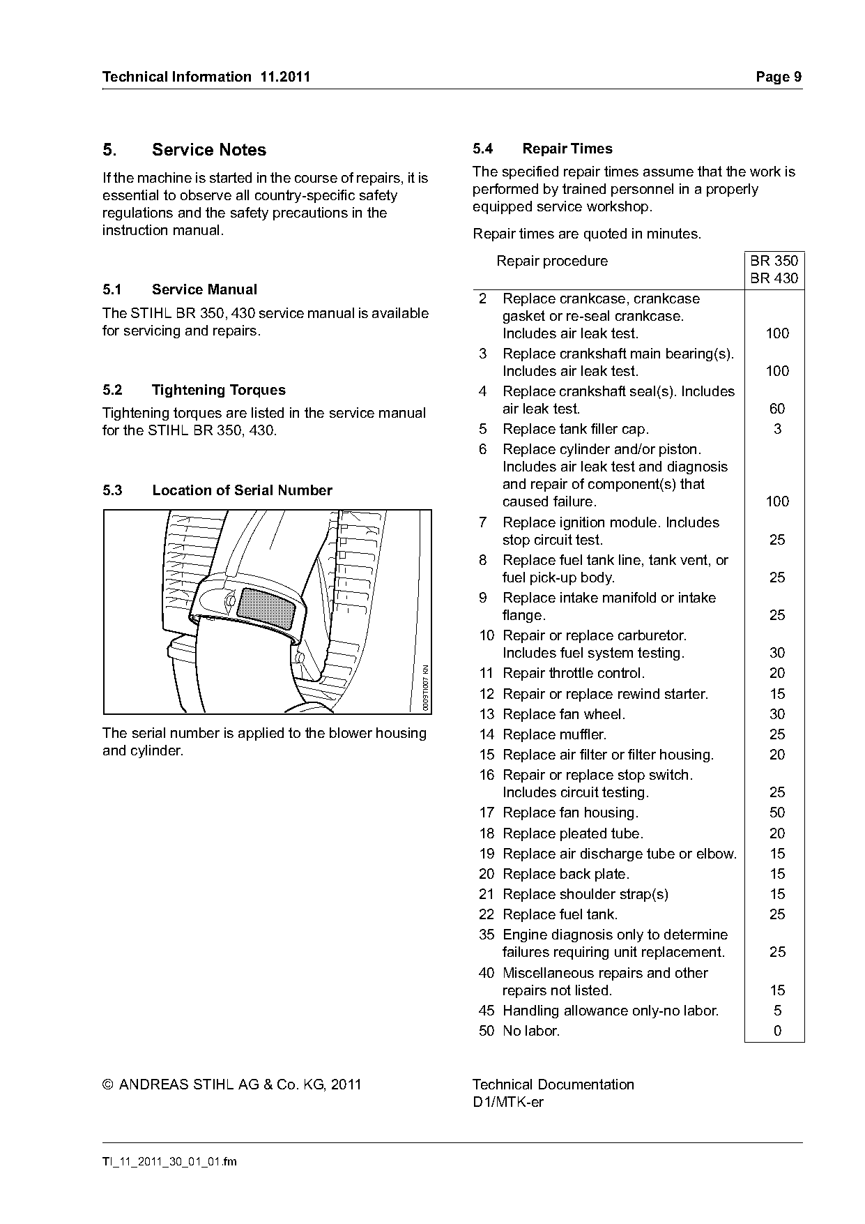
5.3     Location of Serial Number                                        and repair of component(s) that
                                                                         caused failure.                           100
                                                                      7 Replace ignition module. Includes
                                                                         stop circuit test.                        25
                                                                      8 Replace fuel tank line, tank vent, or
                                                                         fuel pick-up body.                        25
                                                                      9 Replace intake manifold or intake
                                                                         flange.                                   25
                                                                      10 Repair or replace carburetor.
                                                                         Includes fuel system testing.             30
                                                       0009TI007 KN

                                                                      11 Repair throttle control.                  20
                                                                      12 Repair or replace rewind starter.         15
                                                                      13 Replace fan wheel.                        30
The serial number is applied to the blower housing                    14 Replace muffler.                          25
and cylinder.                                                         15 Replace air filter or filter housing.     20
                                                                      16 Repair or replace stop switch.
                                                                         Includes circuit testing.                 25
                                                                      17 Replace fan housing.                      50
                                                                      18 Replace pleated tube.                     20
                                                                      19 Replace air discharge tube or elbow.      15
                                                                      20 Replace back plate.                       15
                                                                      21 Replace shoulder strap(s)                 15
                                                                      22 Replace fuel tank.                        25
                                                                      35 Engine diagnosis only to determine
                                                                         failures requiring unit replacement.      25
                                                                      40 Miscellaneous repairs and other
                                                                         repairs not listed.                       15
                                                                      45 Handling allowance only-no labor.         5
                                                                      50 No labor.                                 0

© ANDREAS STIHL AG & Co. KG, 2011                                     Technical Documentation
                                                                      D1/MTK-er

TI_11_2011_30_01_01.fm
Most of these PDFs embed fonts with a shifted character map, so the text above was recovered rather than copied — read it as a faithful but imperfect transcription, and treat the page image above each block as the authority where the two disagree — the figures exist only there, because they are vector drawings that text extraction cannot keep.