Technical Information · issue 17 of 2011
New chain saws STIHL MS 201 C
IssueTI 17/2011
Engine family 1145
Full text
Page 1 of 12
Text of page 1 — search, copy, screen readers
STIH)

Technical Information                           17.2011

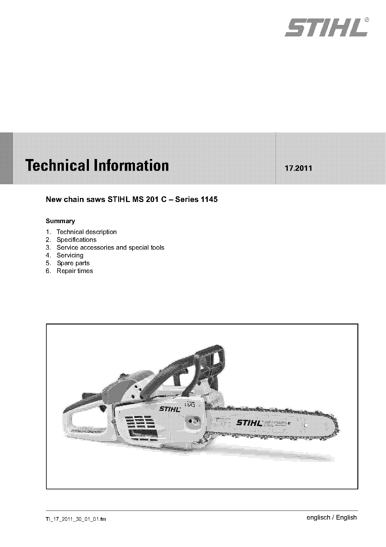
  New chain saws STIHL MS 201 C – Series 1145

  Summary
  1.   Technical description
  2.   Specifications
  3.   Service accessories and special tools
  4.   Servicing
  5.   Spare parts
  6.   Repair times

  TI_17_2011_30_01_01.fm                             englisch / English
Page 2 of 12
Text of page 2 — search, copy, screen readers
Page 2                                                                      Technical Information 17.2011

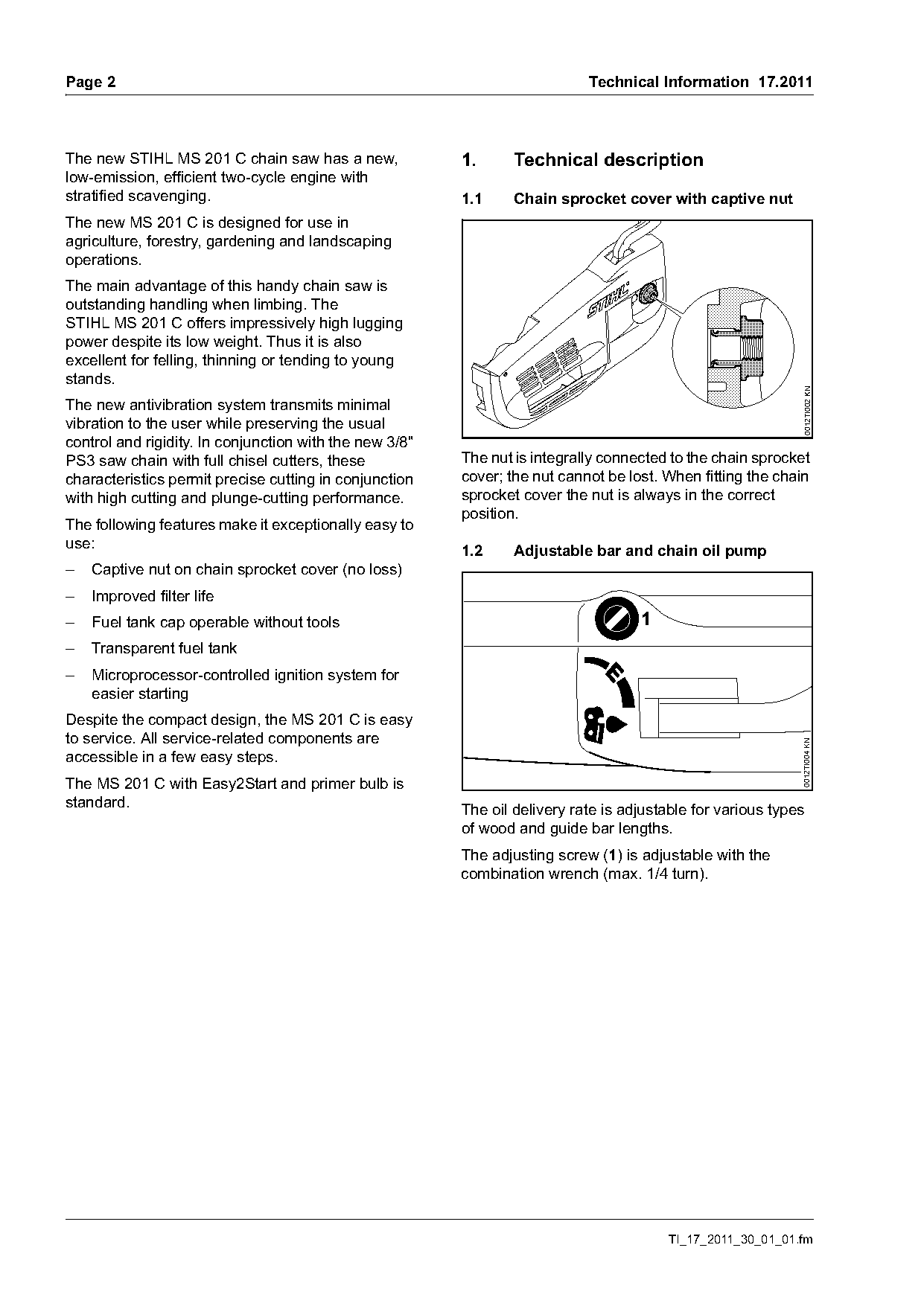
The new STIHL MS 201 C chain saw has a new,              1.      Technical description
low-emission, efficient two-cycle engine with
stratified scavenging.                                   1.1     Chain sprocket cover with captive nut
The new MS 201 C is designed for use in
agriculture, forestry, gardening and landscaping
operations.
The main advantage of this handy chain saw is
outstanding handling when limbing. The
STIHL MS 201 C offers impressively high lugging
power despite its low weight. Thus it is also
excellent for felling, thinning or tending to young
stands.

                                                                                                             0012TI002 KN
The new antivibration system transmits minimal
vibration to the user while preserving the usual
control and rigidity. In conjunction with the new 3/8"
PS3 saw chain with full chisel cutters, these            The nut is integrally connected to the chain sprocket
characteristics permit precise cutting in conjunction    cover; the nut cannot be lost. When fitting the chain
with high cutting and plunge-cutting performance.        sprocket cover the nut is always in the correct
                                                         position.
The following features make it exceptionally easy to
use:
                                                         1.2     Adjustable bar and chain oil pump
–   Captive nut on chain sprocket cover (no loss)
–   Improved filter life
–   Fuel tank cap operable without tools                                            1
–   Transparent fuel tank
–   Microprocessor-controlled ignition system for
    easier starting
Despite the compact design, the MS 201 C is easy
to service. All service-related components are

                                                                                                             0012TI004 KN
accessible in a few easy steps.
The MS 201 C with Easy2Start and primer bulb is
standard.
                                                         The oil delivery rate is adjustable for various types
                                                         of wood and guide bar lengths.
                                                         The adjusting screw (1) is adjustable with the
                                                         combination wrench (max. 1/4 turn).

                                                                                        TI_17_2011_30_01_01.fm
Page 3 of 12
Text of page 3 — search, copy, screen readers
Technical Information 17.2011                                                                                   Page 3

1.3     Winter operation                                          1.4       Service-friendly design
The MS 201 C is equipped with a carburetor heating                All service-relevant components are easily
system.                                                           accessible.
With the carburetor heating system, it is possible to
route heated engine cooling air over the carburetor.
                                                                  Fanwheel side
This prevents carburetor icing under winter
conditions.
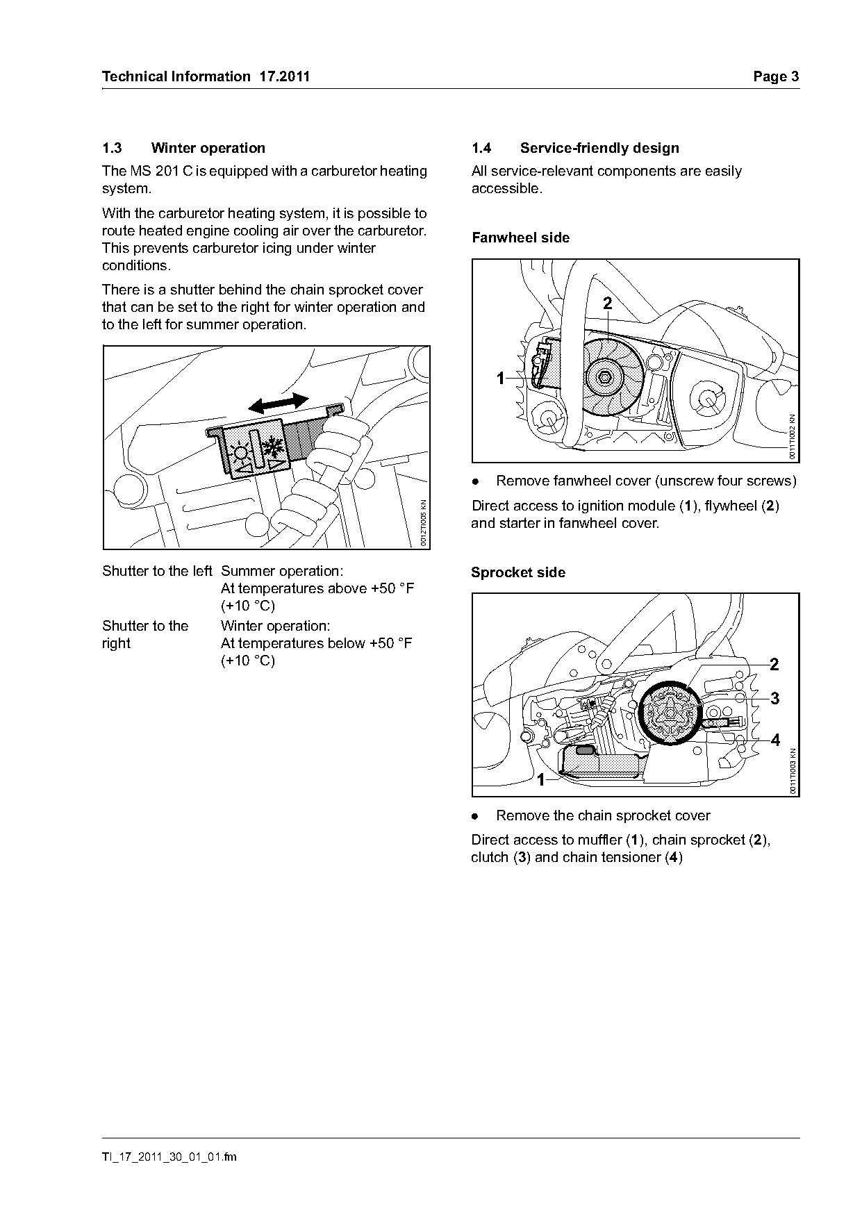
There is a shutter behind the chain sprocket cover
that can be set to the right for winter operation and                                  2
to the left for summer operation.


                                                                                                                       0011TI002 KN
                                                                  .     Remove fanwheel cover (unscrew four screws)
                                                                  Direct access to ignition module (1), flywheel (2)
                                                   0012TI005 KN

                                                                  and starter in fanwheel cover.

Shutter to the left Summer operation:                             Sprocket side
                    At temperatures above +50 °F
                    (+10 °C)
Shutter to the      Winter operation:
right               At temperatures below +50 °F
                    (+10 °C)                                                                                      2
                                                                                                                  3


                                                                                                                       0011TI003 KN
                                                                              1

                                                                  .     Remove the chain sprocket cover
                                                                  Direct access to muffler (1), chain sprocket (2),
                                                                  clutch (3) and chain tensioner (4)

TI_17_2011_30_01_01.fm
Page 4 of 12
Text of page 4 — search, copy, screen readers
Page 4                                                                                  Technical Information 17.2011

Accessing the air filter                                           2.      Specifications

                                                                   2.1     Engine
                                                                   Single cylinder two-stroke engine
                                                                   Displacement:             2.15 cu. in.
                                                                                             (35.2 cm3)
                                                                   Bore:                     1.60 in (40 mm)
         1                                                         Stroke:                   1.10 in (28 mm)
                                                                   Engine power to ISO 7293: 2.4 hp (1.8 kW) at

                                                    0011TI004 KN
                                                                                             9,500 rpm
                                                                   Idle speed:               3,000 rpm
                                                                   Maximum permissible       14,000 rpm
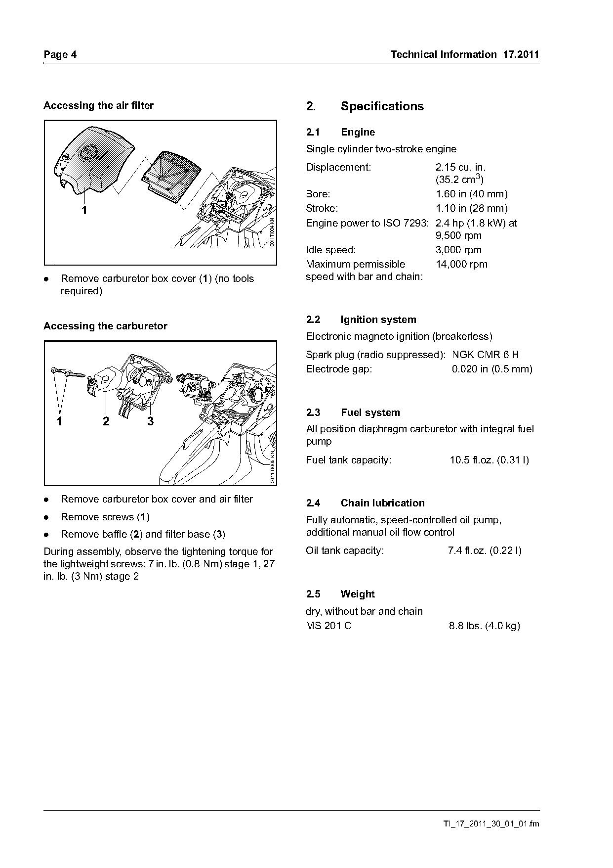
.   Remove carburetor box cover (1) (no tools                      speed with bar and chain:
    required)

                                                                   2.2     Ignition system
Accessing the carburetor
                                                                   Electronic magneto ignition (breakerless)
                                                                   Spark plug (radio suppressed): NGK CMR 6 H
                                                                   Electrode gap:                 0.020 in (0.5 mm)

                                                                   2.3     Fuel system
    1        2          3
                                                                   All position diaphragm carburetor with integral fuel
                                                                   pump
                                                    0011TI005 KN

                                                                   Fuel tank capacity:             10.5 fl.oz. (0.31 l)

.   Remove carburetor box cover and air filter                     2.4     Chain lubrication
.   Remove screws (1)                                              Fully automatic, speed-controlled oil pump,
.   Remove baffle (2) and filter base (3)                          additional manual oil flow control
During assembly, observe the tightening torque for                 Oil tank capacity:              7.4 fl.oz. (0.22 l)
the lightweight screws: 7 in. lb. (0.8 Nm) stage 1, 27
in. lb. (3 Nm) stage 2
                                                                   2.5     Weight
                                                                   dry, without bar and chain
                                                                   MS 201 C                        8.8 lbs. (4.0 kg)

                                                                                                  TI_17_2011_30_01_01.fm
Page 5 of 12
Text of page 5 — search, copy, screen readers
Technical Information 17.2011                   Page 5

2.6     Cutting attachment

2.6.1   Guide bars STIHL ROLLOMATIC® E with
        sprocket nose
STIHL reduced kickback guide bars (with green
label)
Bar lengths:           12, 14, 16 in.
                       (30, 35, 40 cm)
Pitch:                 3/8" P (9.32 mm)
Groove width:          0.50 in. (1.3 mm)
Sprocket nose:         9-tooth

2.6.2   OILOMATIC® saw chains
STIHL reduced kickback saw chain (with green
label)
STIHL PICCO™ Micro™ Comfort 3 (63 PMC3)
Pitch:                 3/8" P (9.32 mm)
Drive link gauge:      0.050 in. (1.3 mm)

STIHL PICCO™ Super 3 (63 PS3)
Pitch:               3/8"P (9.32 mm)
Drive link gauge:    0.050 in. (1.3 mm)

STIHL PICCO™ Duro 3 (63 PD3)
Pitch:               3/8"P (9.32 mm)
Drive link gauge:    0.050 in. (1.3 mm)

2.6.3   Chain sprocket
6-tooth for 3/8"P (spur chain sprocket)

TI_17_2011_30_01_01.fm
Page 6 of 12
Text of page 6 — search, copy, screen readers
Page 6                                                                                 Technical Information 17.2011

3.       Service accessories and special tools

3.1      Service accessories

Designation                       Part number      Use
Set of carburetor parts           1145 007 1700    Carburetor repairs
Locking strip                     1145 893 5900    Blocking the crankshaft for removal of chain sprocket and
                                                   clutch
Grease (225 g tube)               0781 120 1111    Oil seals, oil pump drive, sprocket bearings, chain tensioner
                                                   Bearing and sliding surfaces for throttle trigger, brake lever
                                                   and trigger lockout

3.2      Special tools

3.2.1    To be procured for the STIHL MS 201, MS 201 T
Designation                       Part number                Use
Flange                            5910 850 4203              Engine leakage test, inlet side
Installing sleeve                 1145 893 4600              Protecting the oil seal when pushing it onto the shaft

3.3      Existing special tools
The available special tools are listed in the Service
Manual for the STIHL MS 201, MS 201 T.

3.3.1    Rework information concerning flange
         (for engine leakage test, outlet side)
Flange 5910 855 4201 replaces the previous flange
4224 893 2501.
The previous flange 4224 893 2501 can be
reworked to bring it up to the current status
according to the following drawing.

                          39,25 mm
                                                    0012TI011 KN

                    35 mm

                                                                                                   TI_17_2011_30_01_01.fm
Page 7 of 12
Text of page 7 — search, copy, screen readers
Technical Information 17.2011                                                                                          Page 7

4.        Servicing                                                      4.2      Carburetor adjustment – without limiter
                                                                                  cap
4.1       Removing chain sprocket / clutch – new
          locking strip                                                  4.2.1    New limiter cap
When removing and installing the chain sprocket an                       To comply with various national and international
clutch, a locking strip is required for blocking the                     emission laws and regulations, the new generation
crankshaft.                                                              of limiter caps is used in the MS 201 as already in
                                                                         the MS 261, MS 271 and MS 291.
A new locking strip is being introduced with the
MS 201. It is included with the replacement chain                        Use of the new limiter cap is described in TI 18.2010
sprocket or is available separately under the part                       and TI 25.2010 respectively.
number 1145 893 5900.
                                                                         4.2.2    Removing the limiter cap
The new geometry of the locking strip makes it
much easier to position within the cylinder. The
locking strip can be pushed into the inside of the
cylinder directly through the spark plug opening.
Fastening the locking strip on the cylinder fin
ensures that it is always positioned correctly inside
the cylinder.
.     Unscrew the spark plug
.     Turn the clutch until the piston is in the lower part
      of the cylinder

                                                                                                                                0012TI015 KN
                                                                         .     Screw the puller 5910 890 4502 (special tool)
                                                                               counterclockwise (left-hand thread) about five
                                                                               turns into the limiter cap
                                                                         .     Remove the limiter cap by pulling back the tool
                                                                         .     Use the screwdriver (5910 890 2306) to
                                                                               unscrew the high speed screw (H) with the
                                                                               plastic segment
                                                          0012TI012 KN

.     Insert the locking strip through the opening as
      far as it will go into the cylinder
                                                         0012TI013 KN

.     Fasten the locking strip to the cylinder fin
.     Turn the clutch clockwise until the piston rests
      against the locking strip

TI_17_2011_30_01_01.fm
Page 8 of 12
Text of page 8 — search, copy, screen readers
Page 8                                                                                 Technical Information 17.2011

                                                                   4.2.4   Fitting the limiter cap on the high speed
                                                                           screw


                                                    5902TI018 KN

                                                                                                                        0012TI016 KN
.   If the high speed screw (H) is going to be
    reused, remove the plastic insert
Do not re-install the used cap, since it will be                   .   Orient the new limiter cap (1) so that the
damaged during removal.                                                notch (arrow) points vertically upward
Service work on metering diaphragm, pump                           .   Press the limiter cap (1) onto the high speed
diaphragm, inlet needle, lever, gaskets, choke                         screw (H) until it engages in the first position –
shutter as before.                                                     nearly flush with the dome (arrow) – do not
                                                                       press it in all the way
Do not dismantle the choke shutter, as otherwise the
factory default setting will no longer be correct and
this can lead to impaired engine performance.

4.2.3    Basic setting
After servicing or replacement of the adjusting
screws, it is necessary to perform a basic setting of
the carburetor.
.   Check the air filter – clean or replace it if
    necessary
.   Check the spark arresting screen in the muffler
    – clean or replace it if necessary
The following screwdrivers should be used for the
basic setting.
Low speed screw L
Flat head screwdriver 5910 890 2305
High speed screw H
Screwdriver 5910 890 2306 with hex blade SW 2

.   Carry out basic setting of the adjusting screws –
    set adjusting screw by turning counterclockwise
    starting with the screws firmly seated

Low speed screw L:         1 turn open
High speed screw H:        2 turns open

                                                                                                   TI_17_2011_30_01_01.fm
Page 9 of 12
Text of page 9 — search, copy, screen readers
Technical Information 17.2011                                                                        Page 9

4.2.5    Adjustment                                    4.2.6   Checking the position of the limiter cap
Let the engine warm up before starting adjustments.
Afterwards, allow the engine to idle for 20 seconds.
Do not make any adjustments during this time!
–    The ignition system adjusts the idling
     characteristics

Adjust the specified engine speeds within a                                          1
tolerance range of +/- 200 rpm as follows

                                                                                                              0011TI006 KN
1.    Set speed to 2,800 rpm with idle speed
      adjusting screw (LA)

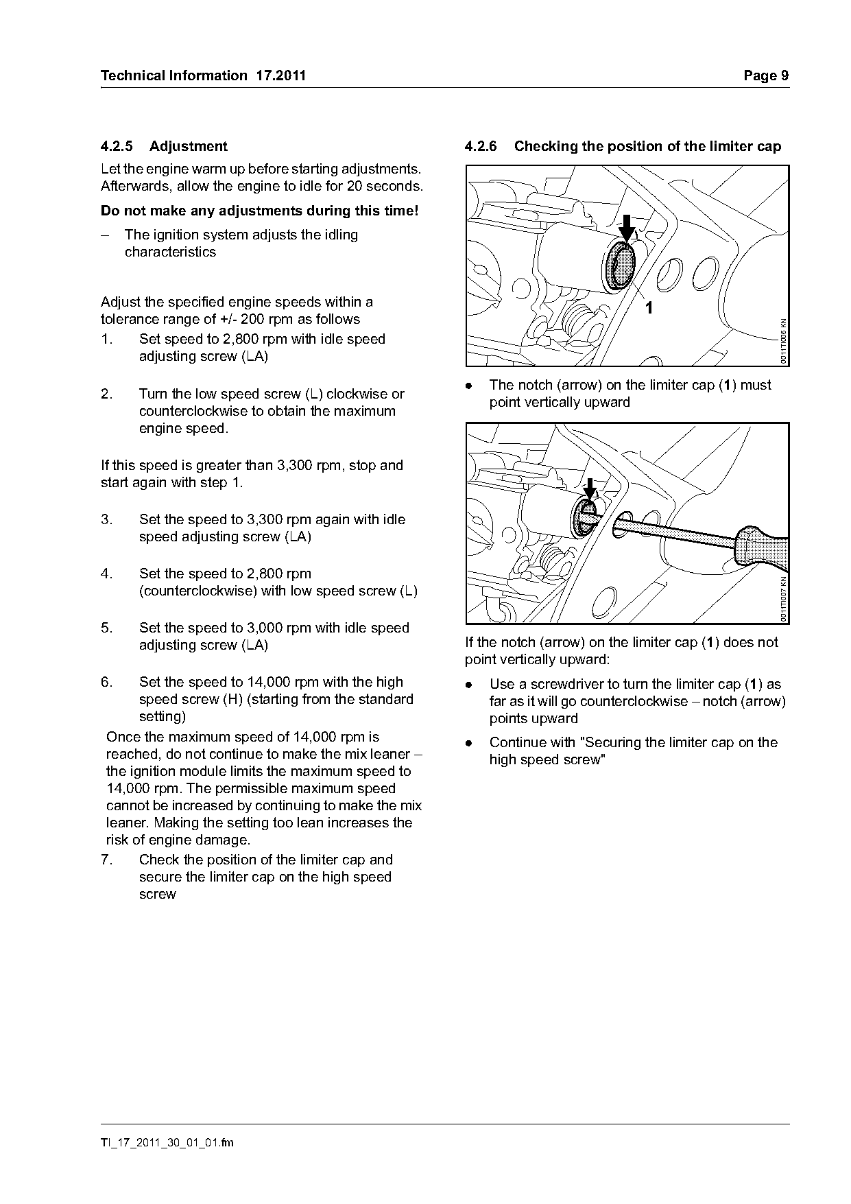
                                                       .   The notch (arrow) on the limiter cap (1) must
2.      Turn the low speed screw (L) clockwise or
                                                           point vertically upward
        counterclockwise to obtain the maximum
        engine speed.

If this speed is greater than 3,300 rpm, stop and
start again with step 1.

3.      Set the speed to 3,300 rpm again with idle
        speed adjusting screw (LA)

4.      Set the speed to 2,800 rpm

                                                                                                              0011TI007 KN
        (counterclockwise) with low speed screw (L)

5.      Set the speed to 3,000 rpm with idle speed
        adjusting screw (LA)                           If the notch (arrow) on the limiter cap (1) does not
                                                       point vertically upward:
6.     Set the speed to 14,000 rpm with the high       .   Use a screwdriver to turn the limiter cap (1) as
       speed screw (H) (starting from the standard         far as it will go counterclockwise – notch (arrow)
       setting)                                            points upward
 Once the maximum speed of 14,000 rpm is               .   Continue with "Securing the limiter cap on the
 reached, do not continue to make the mix leaner –         high speed screw"
 the ignition module limits the maximum speed to
 14,000 rpm. The permissible maximum speed
 cannot be increased by continuing to make the mix
 leaner. Making the setting too lean increases the
 risk of engine damage.
7.     Check the position of the limiter cap and
       secure the limiter cap on the high speed
       screw

TI_17_2011_30_01_01.fm
Page 10 of 12
Text of page 10 — search, copy, screen readers
Page 10                                                                                   Technical Information 17.2011

4.2.7     Securing the limiter cap on the high                      Notes regarding press fluid OH 723
          speed screw
                                                                    Press fluid OH 723 produces a lubricant film that
                                                                    simplifies assembly. The lubricant evaporates after
                                                                    a short time – the hose is firmly seated.
                                                                    Never use fuel, oil or grease as a lubricant. Fuel, oil
                                                                    and grease do not evaporate – the hose may come
                                                                    loose.

                                                                    4.4       Carburetor adjustment – with limiter cap

                                                     0011TI008 KN
                                                                    With this carburetor, the high speed screw H can be
                                                                    adjusted by the user within a range of an approx. 3/4
                                                                    turn.
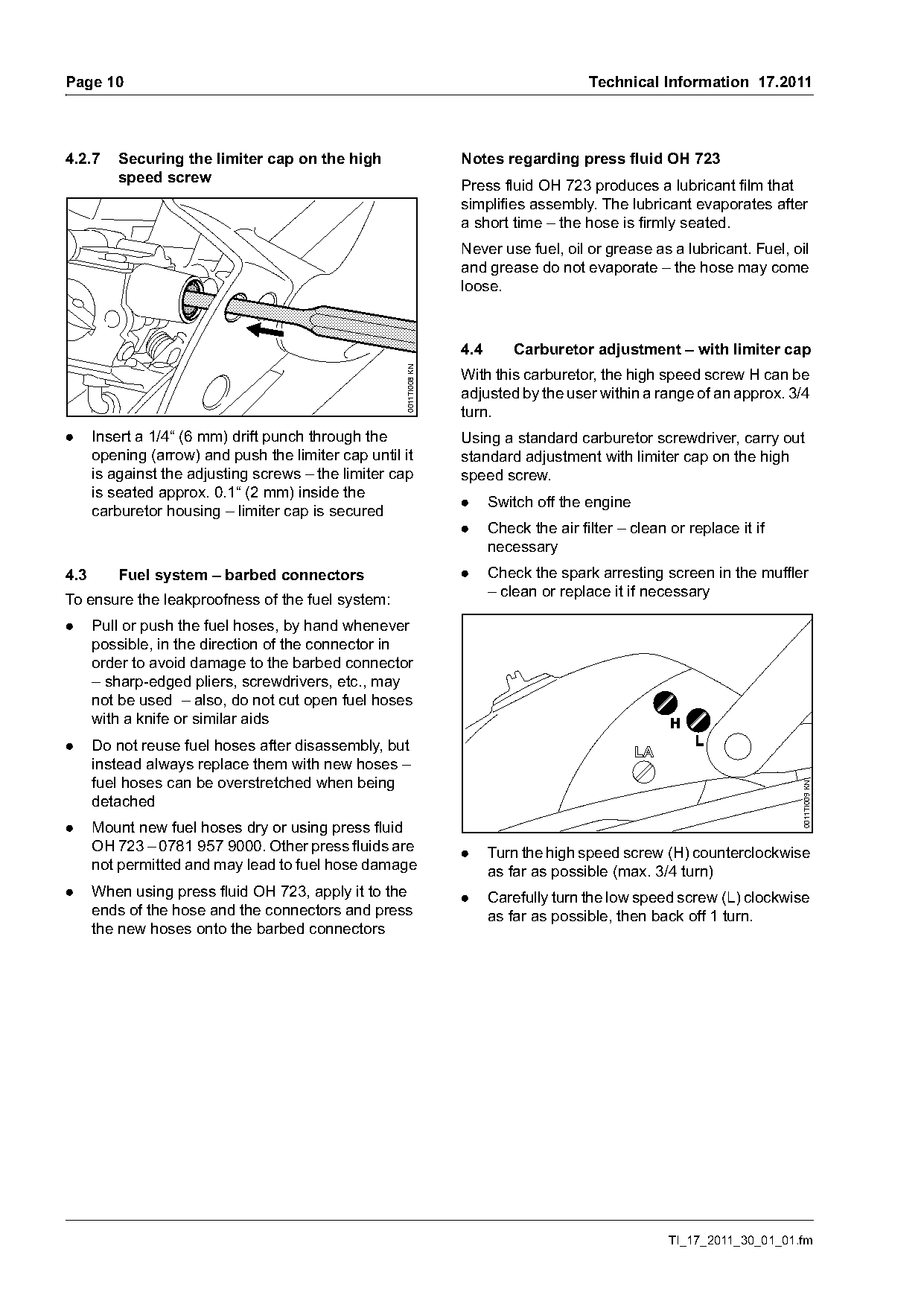
.     Insert a 1/4“ (6 mm) drift punch through the                  Using a standard carburetor screwdriver, carry out
      opening (arrow) and push the limiter cap until it             standard adjustment with limiter cap on the high
      is against the adjusting screws – the limiter cap             speed screw.
      is seated approx. 0.1“ (2 mm) inside the
                                                                    .     Switch off the engine
      carburetor housing – limiter cap is secured
                                                                    .     Check the air filter – clean or replace it if
                                                                          necessary
4.3       Fuel system – barbed connectors                           .     Check the spark arresting screen in the muffler
                                                                          – clean or replace it if necessary
To ensure the leakproofness of the fuel system:
.     Pull or push the fuel hoses, by hand whenever
      possible, in the direction of the connector in
      order to avoid damage to the barbed connector
      – sharp-edged pliers, screwdrivers, etc., may
      not be used – also, do not cut open fuel hoses
      with a knife or similar aids
.     Do not reuse fuel hoses after disassembly, but
      instead always replace them with new hoses –
      fuel hoses can be overstretched when being
      detached                                                                                                             0011TI009 KN

.     Mount new fuel hoses dry or using press fluid
      OH 723 – 0781 957 9000. Other press fluids are                .     Turn the high speed screw (H) counterclockwise
      not permitted and may lead to fuel hose damage                      as far as possible (max. 3/4 turn)
.     When using press fluid OH 723, apply it to the                .     Carefully turn the low speed screw (L) clockwise
      ends of the hose and the connectors and press                       as far as possible, then back off 1 turn.
      the new hoses onto the barbed connectors

                                                                                                       TI_17_2011_30_01_01.fm
Page 11 of 12
Text of page 11 — search, copy, screen readers
Technical Information 17.2011                                                                                  Page 11

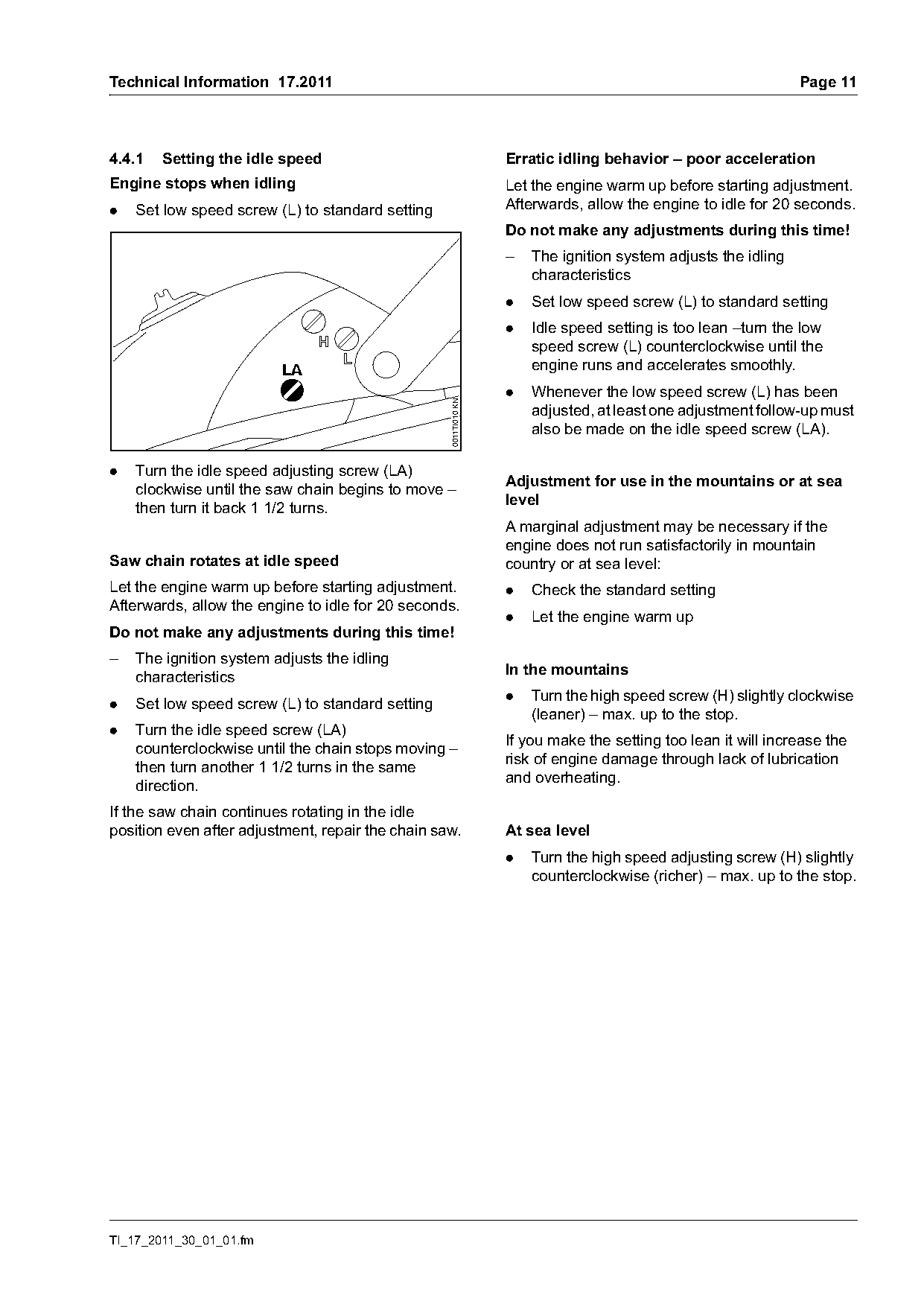
4.4.1   Setting the idle speed                                    Erratic idling behavior – poor acceleration
Engine stops when idling                                          Let the engine warm up before starting adjustment.
.   Set low speed screw (L) to standard setting                   Afterwards, allow the engine to idle for 20 seconds.
                                                                  Do not make any adjustments during this time!
                                                                  –   The ignition system adjusts the idling
                                                                      characteristics
                                                                  .   Set low speed screw (L) to standard setting
                                                                  .   Idle speed setting is too lean –turn the low
                                                                      speed screw (L) counterclockwise until the
                                                                      engine runs and accelerates smoothly.
                                                                  .   Whenever the low speed screw (L) has been

                                                   0011TI010 KN
                                                                      adjusted, at least one adjustment follow-up must
                                                                      also be made on the idle speed screw (LA).

.   Turn the idle speed adjusting screw (LA)
                                                                  Adjustment for use in the mountains or at sea
    clockwise until the saw chain begins to move –
                                                                  level
    then turn it back 1 1/2 turns.
                                                                  A marginal adjustment may be necessary if the
                                                                  engine does not run satisfactorily in mountain
Saw chain rotates at idle speed                                   country or at sea level:
Let the engine warm up before starting adjustment.                .   Check the standard setting
Afterwards, allow the engine to idle for 20 seconds.
                                                                  .   Let the engine warm up
Do not make any adjustments during this time!
–   The ignition system adjusts the idling
                                                                  In the mountains
    characteristics
                                                                  .   Turn the high speed screw (H) slightly clockwise
.   Set low speed screw (L) to standard setting
                                                                      (leaner) – max. up to the stop.
.   Turn the idle speed screw (LA)
                                                                  If you make the setting too lean it will increase the
    counterclockwise until the chain stops moving –
                                                                  risk of engine damage through lack of lubrication
    then turn another 1 1/2 turns in the same
                                                                  and overheating.
    direction.
If the saw chain continues rotating in the idle
position even after adjustment, repair the chain saw.             At sea level
                                                                  .   Turn the high speed adjusting screw (H) slightly
                                                                      counterclockwise (richer) – max. up to the stop.

TI_17_2011_30_01_01.fm
Page 12 of 12
Text of page 12 — search, copy, screen readers
Page 12                                                                            Technical Information 17.2011

5.     Spare parts
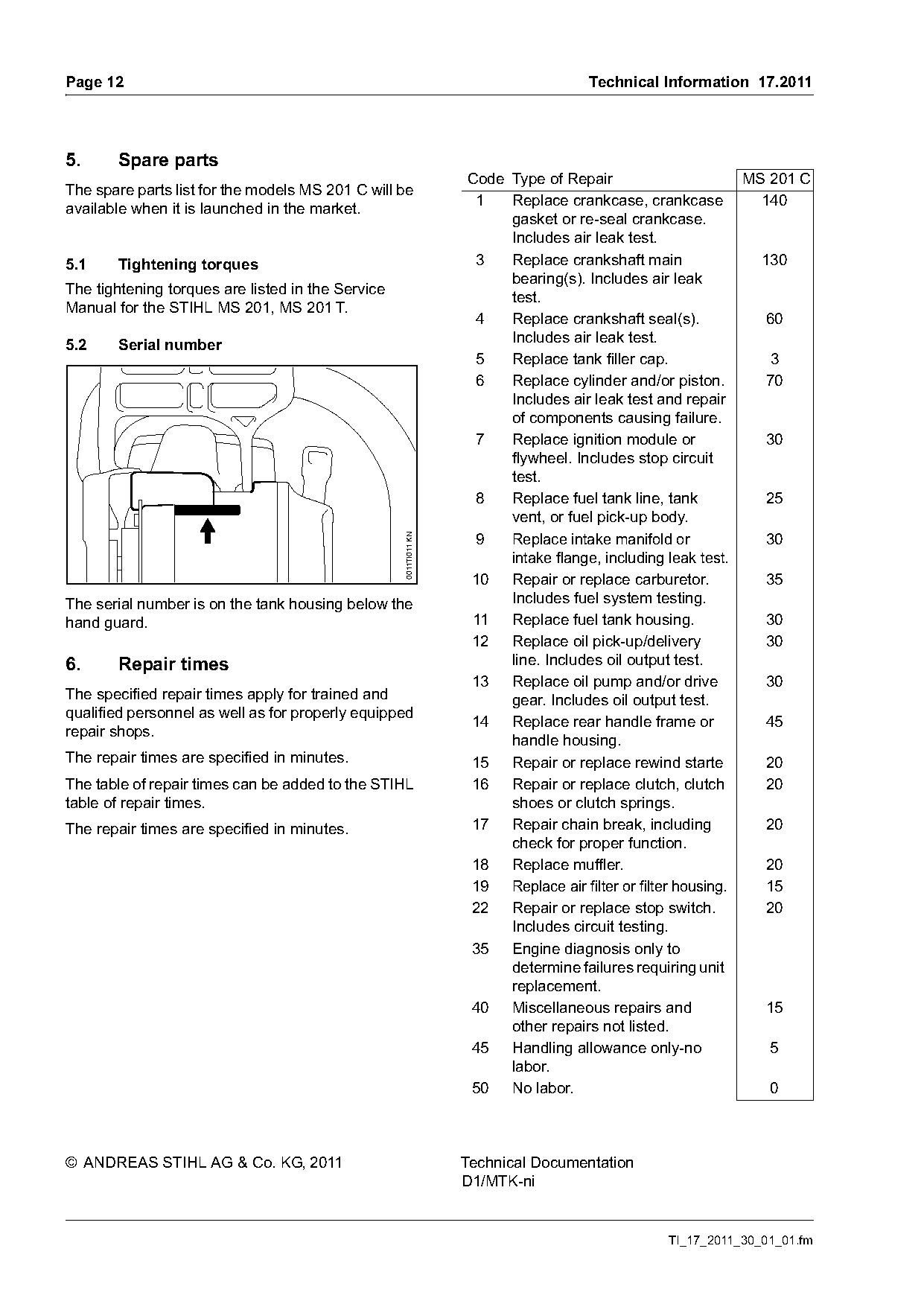
                                                                  Code Type of Repair                      MS 201 C
The spare parts list for the models MS 201 C will be
                                                                   1   Replace crankcase, crankcase          140
available when it is launched in the market.
                                                                       gasket or re-seal crankcase.
                                                                       Includes air leak test.
5.1    Tightening torques                                          3   Replace crankshaft main               130
                                                                       bearing(s). Includes air leak
The tightening torques are listed in the Service
                                                                       test.
Manual for the STIHL MS 201, MS 201 T.
                                                                   4   Replace crankshaft seal(s).            60
5.2    Serial number                                                   Includes air leak test.
                                                                   5   Replace tank filler cap.               3
                                                                   6   Replace cylinder and/or piston.        70
                                                                       Includes air leak test and repair
                                                                       of components causing failure.
                                                                   7   Replace ignition module or             30
                                                                       flywheel. Includes stop circuit
                                                                       test.
                                                                   8   Replace fuel tank line, tank           25
                                                                       vent, or fuel pick-up body.
                                                                   9   Replace intake manifold or             30
                                                   0011TI011 KN

                                                                       intake flange, including leak test.
                                                                  10 Repair or replace carburetor.            35
The serial number is on the tank housing below the                     Includes fuel system testing.
hand guard.                                                       11   Replace fuel tank housing.             30
                                                                  12 Replace oil pick-up/delivery             30
6.     Repair times                                                    line. Includes oil output test.
                                                                  13 Replace oil pump and/or drive            30
The specified repair times apply for trained and                       gear. Includes oil output test.
qualified personnel as well as for properly equipped
                                                                  14 Replace rear handle frame or             45
repair shops.
                                                                       handle housing.
The repair times are specified in minutes.                        15 Repair or replace rewind starte          20
The table of repair times can be added to the STIHL               16 Repair or replace clutch, clutch         20
table of repair times.                                                 shoes or clutch springs.
The repair times are specified in minutes.                        17 Repair chain break, including            20
                                                                       check for proper function.
                                                                  18 Replace muffler.                         20
                                                                  19 Replace air filter or filter housing.    15
                                                                  22 Repair or replace stop switch.           20
                                                                       Includes circuit testing.
                                                                  35 Engine diagnosis only to
                                                                       determine failures requiring unit
                                                                       replacement.
                                                                  40 Miscellaneous repairs and                15
                                                                       other repairs not listed.
                                                                  45 Handling allowance only-no               5
                                                                       labor.
                                                                  50 No labor.                                0

© ANDREAS STIHL AG & Co. KG, 2011                                 Technical Documentation
                                                                  D1/MTK-ni

                                                                                              TI_17_2011_30_01_01.fm
Most of these PDFs embed fonts with a shifted character map, so the text above was recovered rather than copied — read it as a faithful but imperfect transcription, and treat the page image above each block as the authority where the two disagree — the figures exist only there, because they are vector drawings that text extraction cannot keep.