Technical Information · issue 22 of 2011
Gear Housing; Service Notes; Summary
IssueTI 22/2011
Part changes (1)
| Was | Becomes | What the bulletin says |
|---|---|---|
| 4138 641 0300 | 4138 640 0551 | Gear Housing The previous gear housing 4138 641 0300 is no longer available as a replacement part from the factory and will be replaced by the new gear housing assembly 4138 640 0551. |
Full text
Page 1 of 3
Text of page 1 — search, copy, screen readers
STIH)

Technical Information                                                          22.2011

  STIHL HT 70, HT 75 Pole Pruners – Series 4138
  STIHL HT 73 Pole Pruner – Series 4142
  STIHL HTE 60 Pole Pruner – Series 4810
  STIHL HT-KM Pole Pruner KombiTool – Series 4138
  STIHL HT Pole Pruner Attachment – Series 4138

  Contents
  1. Gear Housing
  2. Service Notes
  3. Summary

  1.      Gear Housing
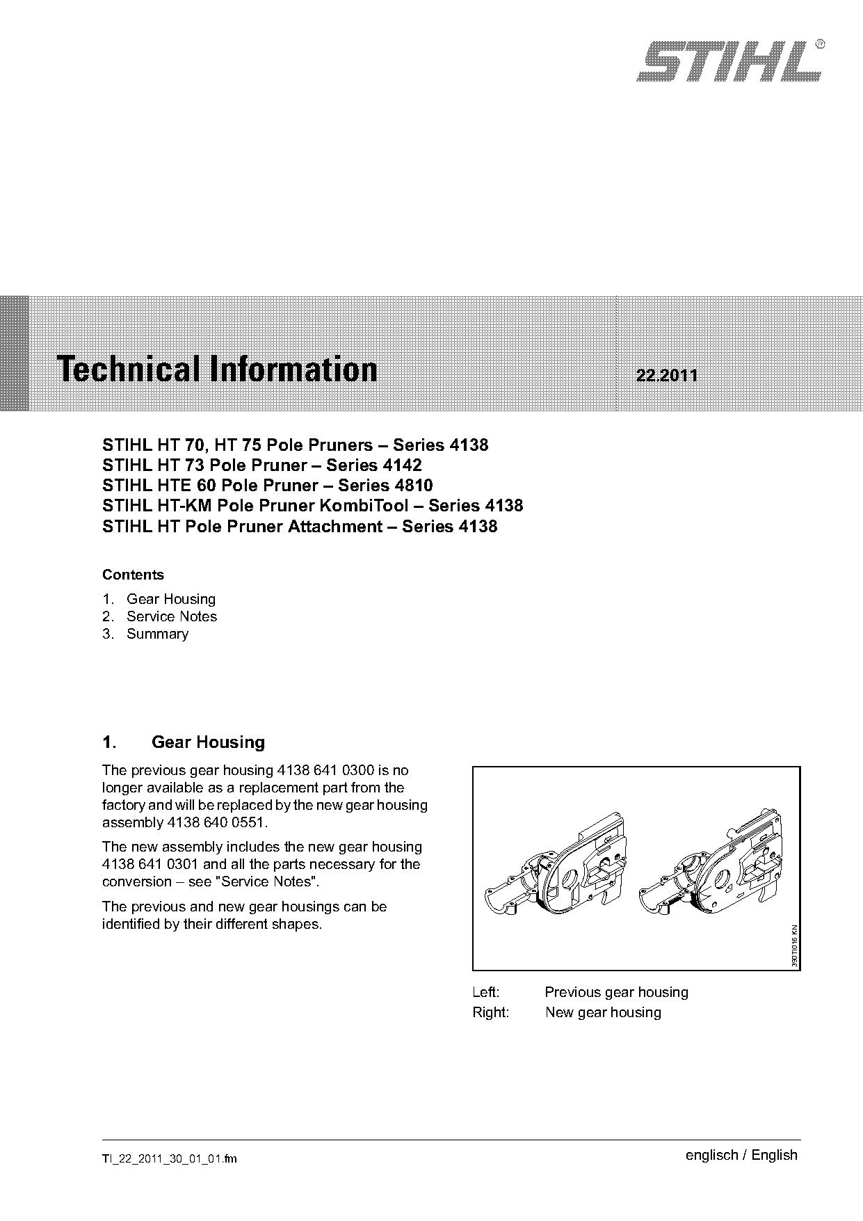
  The previous gear housing 4138 641 0300 is no
  longer available as a replacement part from the
  factory and will be replaced by the new gear housing
  assembly 4138 640 0551.
  The new assembly includes the new gear housing
  4138 641 0301 and all the parts necessary for the
  conversion – see "Service Notes".
  The previous and new gear housings can be
  identified by their different shapes.
                                                                                                      390TI016 KN

                                                         Left:    Previous gear housing
                                                         Right:   New gear housing

  TI_22_2011_30_01_01.fm                                                              englisch / English
Page 2 of 3
Text of page 2 — search, copy, screen readers
Page 2                                                                      Technical Information 22.2011

2.       Service Notes
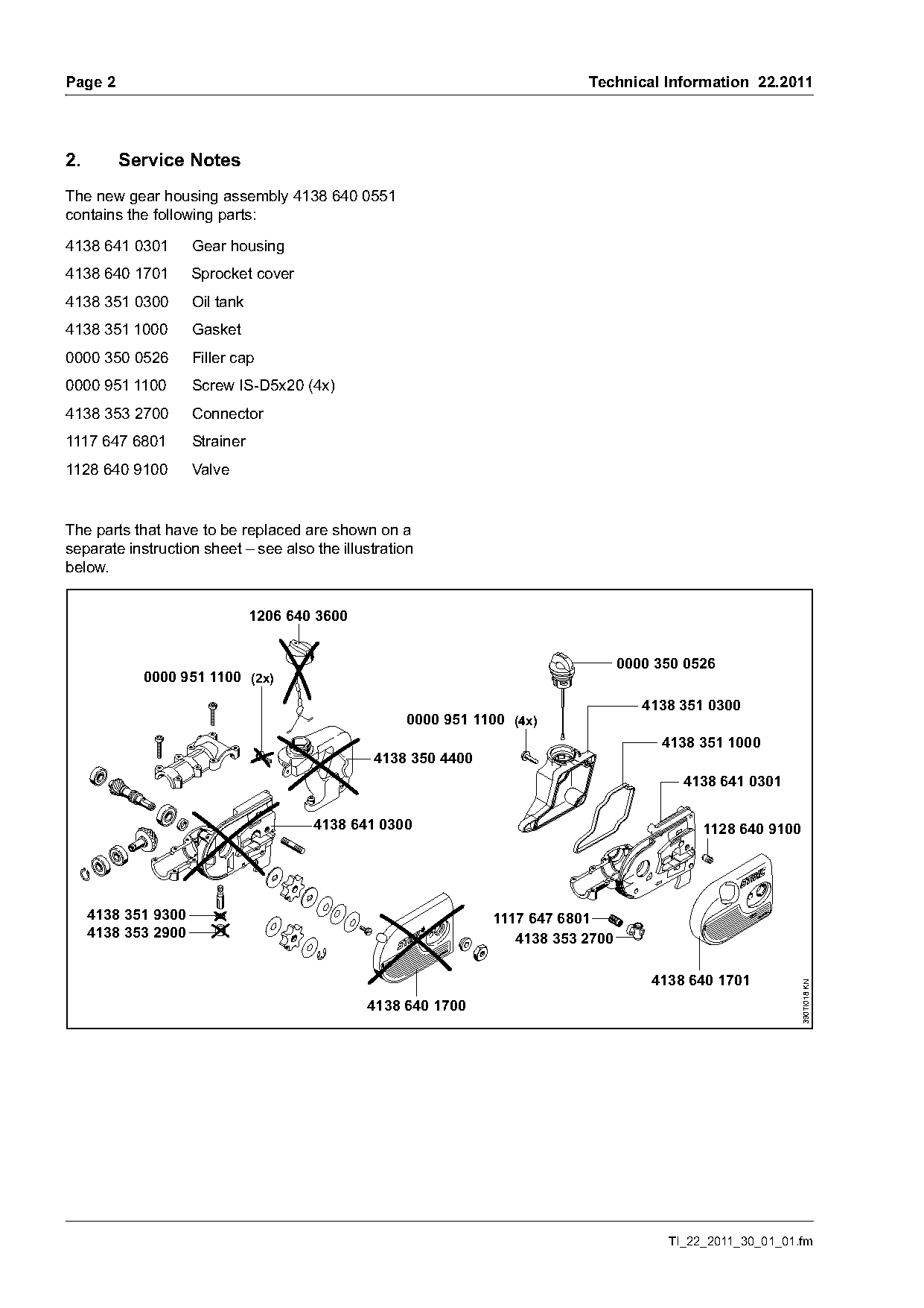
The new gear housing assembly 4138 640 0551
contains the following parts:

4138 641 0301        Gear housing
4138 640 1701        Sprocket cover
4138 351 0300        Oil tank
4138 351 1000        Gasket
0000 350 0526        Filler cap
0000 951 1100        Screw IS-D5x20 (4x)
4138 353 2700        Connector
1117 647 6801        Strainer
1128 640 9100        Valve

The parts that have to be replaced are shown on a
separate instruction sheet – see also the illustration
below.

                                1206 640 3600

                                                                                   0000 350 0526
            0000 951 1100 (2x)
                                                                                      4138 351 0300
                                                     0000 951 1100 (4x)
                                                                                        4138 351 1000
                                                4138 350 4400
                                                                                           4138 641 0301

                                        4138 641 0300                                         1128 640 9100

     4138 351 9300                                              1117 647 6801
     4138 353 2900                                                 4138 353 2700

                                                                                       4138 640 1701
                                                                                                              390TI018 KN

                                                4138 640 1700

                                                                                         TI_22_2011_30_01_01.fm
Page 3 of 3
Text of page 3 — search, copy, screen readers
Technical Information 22.2011                                                                       Page 3

3.      Summary
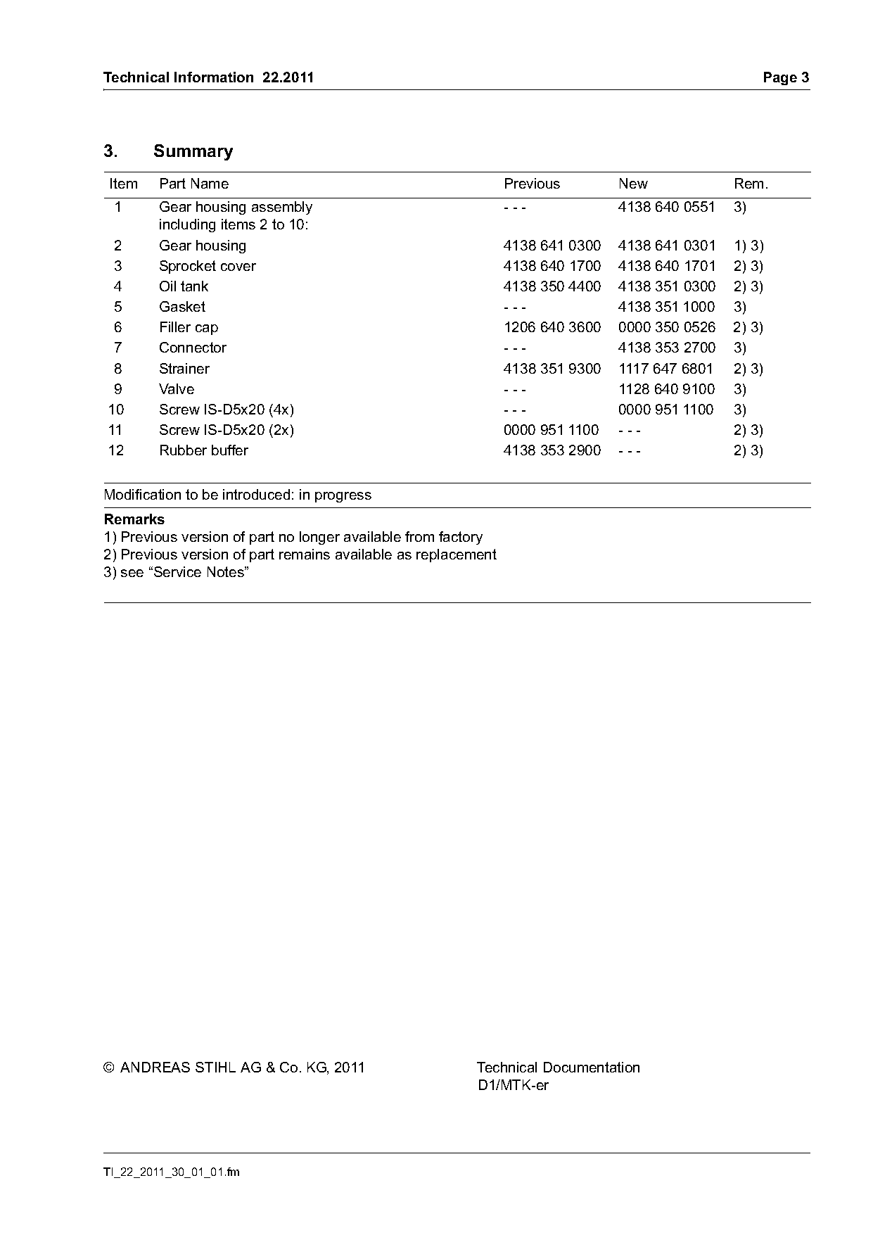
Item    Part Name                                              Previous        New             Rem.
 1      Gear housing assembly                                  ---             4138 640 0551   3)
        including items 2 to 10:
 2      Gear housing                                           4138 641 0300   4138 641 0301   1) 3)
 3      Sprocket cover                                         4138 640 1700   4138 640 1701   2) 3)
 4      Oil tank                                               4138 350 4400   4138 351 0300   2) 3)
 5      Gasket                                                 ---             4138 351 1000   3)
 6      Filler cap                                             1206 640 3600   0000 350 0526   2) 3)
 7      Connector                                              ---             4138 353 2700   3)
 8      Strainer                                               4138 351 9300   1117 647 6801   2) 3)
 9      Valve                                                  ---             1128 640 9100   3)
10      Screw IS-D5x20 (4x)                                    ---             0000 951 1100   3)
11      Screw IS-D5x20 (2x)                                    0000 951 1100   ---             2) 3)
12      Rubber buffer                                          4138 353 2900   ---             2) 3)

Modification to be introduced: in progress
Remarks
1) Previous version of part no longer available from factory
2) Previous version of part remains available as replacement
3) see “Service Notes”

© ANDREAS STIHL AG & Co. KG, 2011                        Technical Documentation
                                                         D1/MTK-er

TI_22_2011_30_01_01.fm
Most of these PDFs embed fonts with a shifted character map, so the text above was recovered rather than copied — read it as a faithful but imperfect transcription, and treat the page image above each block as the authority where the two disagree — the figures exist only there, because they are vector drawings that text extraction cannot keep.