Technical Information · issue 28 of 2011
STIHL MDG 1 Engine Analyzer
IssueTI 28/2011
Full text
Page 1 of 6
Text of page 1 — search, copy, screen readers
STIH)

Technical Information                                                                       28.2011

  STIHL MDG 1 Engine Analyzer – Series 5910

  Contents
  1.   STIHL MDG 1
  2.   Technical Description
  3.   Selecting Power Tool
  4.   Functions and Symbols
  5.   Preparing Power Tool and Engine Analyzer
  6.   STIHL ADG 1
  7.   Chain Without Cutters

  1.      STIHL MDG 1
                                                                 The STIHL MDG 1 engine analyzer is used to test
                                                                 ignition modules and control units (STIHL
                                                                 M-TronicTM) and connected electrical components
                                                                 quickly and reliably.
                                                                 The STIHL MDG 1 enables the right action to be
                                                                 taken at the right time.
                                                                 All other diagnostic and repair procedures, e.g.
                                                                 testing engine for leaks or looking for faults in fuel
                                                                 system, remain unchanged.
                                                  5901TI000 KN

                                                                 It is possible to generate a report after every test.
                                                                 The report lists the individual steps and results of
  The STIHL MDG 1 engine analyzer and STIHL                      the test run. The report may be printed out and
  diagnostic software have been designed for                     saved.
  analyzing specific parts, troubleshooting and                  In addition, dealer and customer data, serial
  performing adjustments.                                        number, company logo and the name of the service
  A computer is required to use the STIHL MDG 1                  technician can be included in the report.
  engine analyzer and the diagnostic software                    The STIHL MDG 1 can be used to test STIHL power
  supplied with it, see 2.1System Requirements.                  tools manufactured from 2000 up to the present day.

  TI_28_2011_30_01_01.fm                                                                             englisch / English
Page 2 of 6
Text of page 2 — search, copy, screen readers
Page 2                                                                 Technical Information 28.2011

2.       Technical Description


                                                                              8
                        6
                                1


                                                                                                       5901TI001 KN
                                                                                         4

Bluetooth wireless technology is used to transmit    Operating System
information between the STIHL engine analyzer (1)
and the computer (2). A free USB port for the        –   Microsoft® Windows® XP with
bluetooth USB stick (3) or an internal bluetooth         Service Pack 3 (SP3) or
function is required for this purpose.               –   Microsoft® Windows Vista® or
The power supply unit (4) provides the STIHL
                                                     –   Microsoft® Windows® 7
MDG 1 with power. The STIHL MDG 1 is connected
between the spark plug boot (5) and spark plug (6)   Software Requirements
to test STIHL power tools. Power tools with
                                                     –   Microsoft® .NET 3.5 or higher
STIHL M-TronicTM are connected to the diagnostic
socket (8) with the "STIHL M-TronicTM" test          –   Adobe® Acrobat® Reader 9 or higher
cable (7).                                           Hardware Requirements

2.1      System Requirements                         Minimum Requirements

STIHL diagnostic software may only be installed on   –   CPU 1 GHz
a computer that meets the system requirements.       –   256 MB free memory
Administrator rights are required for installation
                                                     –   Minimum of 100 MB hard disk space
under Microsoft® Windows® – contact the system
administrator if necessary.                          –   SVGA monitor (minimum resolution 1024 x 768)
                                                     –   USB interface 1.1 or higher
                                                     –   CD-ROM or DVD drive

                                                                                   TI_28_2011_30_01_01.fm
Page 3 of 6
Text of page 3 — search, copy, screen readers
Technical Information 28.2011                                                                         Page 3

Recommended Requirements                                 2.3     Updating STIHL Diagnostic Software
–     CPU 1 GHz                                          The introduction of new power tools and additional
                                                         diagnostic functions necessitate a software update.
–     512 MB free memory
                                                         The update can be performed as described below.
–     Minimum of 100 MB hard disk space
–     SVGA monitor (minimum resolution 1024 x 768)       2.3.1   Direct Update via Internet
                                                         Computer with diagnostic software has internet
–     USB interface 1.1 or higher
                                                         access:
–     CD-ROM or DVD drive
                                                         In the menu bar, click on the question mark "?" –
                                                         select "Check for updates... ". The diagnostic
2.2      Installation of STIHL Diagnostic Software
                                                         software checks whether an update is available. If
Check system requirements before installation.           yes, the update is performed automatically.
It is essential to observe the sequence of the steps
described. Only then will the STIHL diagnostic           2.3.2   Indirect Update (without Internet)
software be properly installed in the computer.          Computer with diagnostic software has no internet
Do not connect the analyzer (MDG 1, ADG 1) to the        access:
computer until installation of the STIHL diagnostic      The data for updating the diagnostic software is
software is completed.                                   supplied by the sales company.

2.2.1    Installation                                    2.4     STIHL MDG 1 Instruction Manual
Place CD-ROM in computer's CD-ROM or DVD                 In the menu bar, click on the question mark "?" –
drive.                                                   select "Instruction manual". The instruction manual
                                                         is opened.
2.2.2    Automatic Start
The automatic start works only if the computer           3.      Selecting Power Tool
supports automatic starting of a program from a CD-
ROM (AUTORUN). Then follow the installation              The power tool must be selected before starting the
steps of the diagnostic software.                        individual diagnostic functions and steps.

If the setup program is not started automatically,       Power tools with STIHL M-TronicTM engine
start it manually.                                       management are listed separately and must be
                                                         selected, e.g. MS 441 C-M.
2.2.3    Manual Start                                    Select "Other STIHL Products" for basic diagnosis
Open My Computer and select CD-ROM or DVD-               of STIHL power tools manufactured from 2000 up to
ROM drive. Start installation by double click on         the present day.
"Setup.exe". Then follow the installation steps of the
diagnostic software.

TI_28_2011_30_01_01.fm
Page 4 of 6
Text of page 4 — search, copy, screen readers
Page 4                                                                                     Technical Information 28.2011

4.        Functions and Symbols                                    4.1.2     STIHL M-TronicTM Engine Management

The individual functions and test steps are identified             Specific parts diagnosis and troubleshooting for M-
by the following symbols. The "operating data" and                 Tronic engine management.
"calibration" functions are only available for power               –     Solenoid valve is tested electrically
tools with STIHL M-TronicTM.                                       –     Operating data are read out – control unit and
                                                                         analyzer exchange information, e.g. part
              1                                                          number of control unit.
                                        2                          –     Positions of Master Control lever / slide control
                                                                         are tested – positions Stop 0, Start } and
                                                                         Run F must be selected for this purpose.
                                                                   The following points are tested during the test run:
                                                                   –     Ignition voltage
                                                                   –     Ignition spark
                                                                   –     Spark advance (non suppressed spark plug)
                  3                                                –     Short circuit
                                                                   –     Ignition timing
                                        4
                                                                   –     Mixture control
                                                                   –     Idle control
                                                    5901TI002 KN

                                                                   –     Maximum engine speed

1      Diagnosis                                                   4.2       Tachometer
       – Basic diagnosis
       – STIHL M-TronicTM engine management                        Tachometer with slave pointer and short-term
                                                                   memory for momentary maximum engine speed.
2      Tachometer
                                                                   Slave pointer and short-term memory simplify
3      Operating data                                              carburetor adjustment.
       (only for STIHL M-TronicTM engine
       management)                                                 4.3       Operating Data
4      Calibration
                                                                   Control unit and analyzer exchange information.
       (only for STIHL M-TronicTM engine
                                                                   The part numbers of the control unit and the
       management)
                                                                   software version are displayed.
4.1       Diagnosis                                                4.4       Calibration
The STIHL MDG 1 enables the right action to be                     If the control unit or carburetor are replaced in the
taken at the right time.
                                                                   service shop, the STIHL M-TronicTM has to be
                                                                   re-calibrated.
4.1.1     Basic Diagnosis
Ignition modules and components of STIHL power                     The control unit is adjusted to match the carburetor
tools manufactured from 2000 can be tested, simply,                during the run in the Start position }. An immediate
reliably and quickly with the STIHL MDG 1.                         shutdown is necessary to store the information.

The following points are tested during the test run:
–     Ignition voltage
–     Ignition spark
–     Spark advance
–     Short circuit

                                                                                                     TI_28_2011_30_01_01.fm
Page 5 of 6
Text of page 5 — search, copy, screen readers
Technical Information 28.2011                                                                                      Page 5

5.       Preparing Power Tool and Engine
         Analyzer
–    Country-specific safety regulations and the
     safety precautions in the instruction manuals
     must be observed when operating the power
     tool and engine analyzer.
–    The engine analyzer may be operated only if it
     is in good working order.

                                                                                                                          5901TI004 KN
–    Use the engine analyzer only for testing STIHL
     power tools made from 2000 to present day.
–    Visual inspection – check exterior of power tool
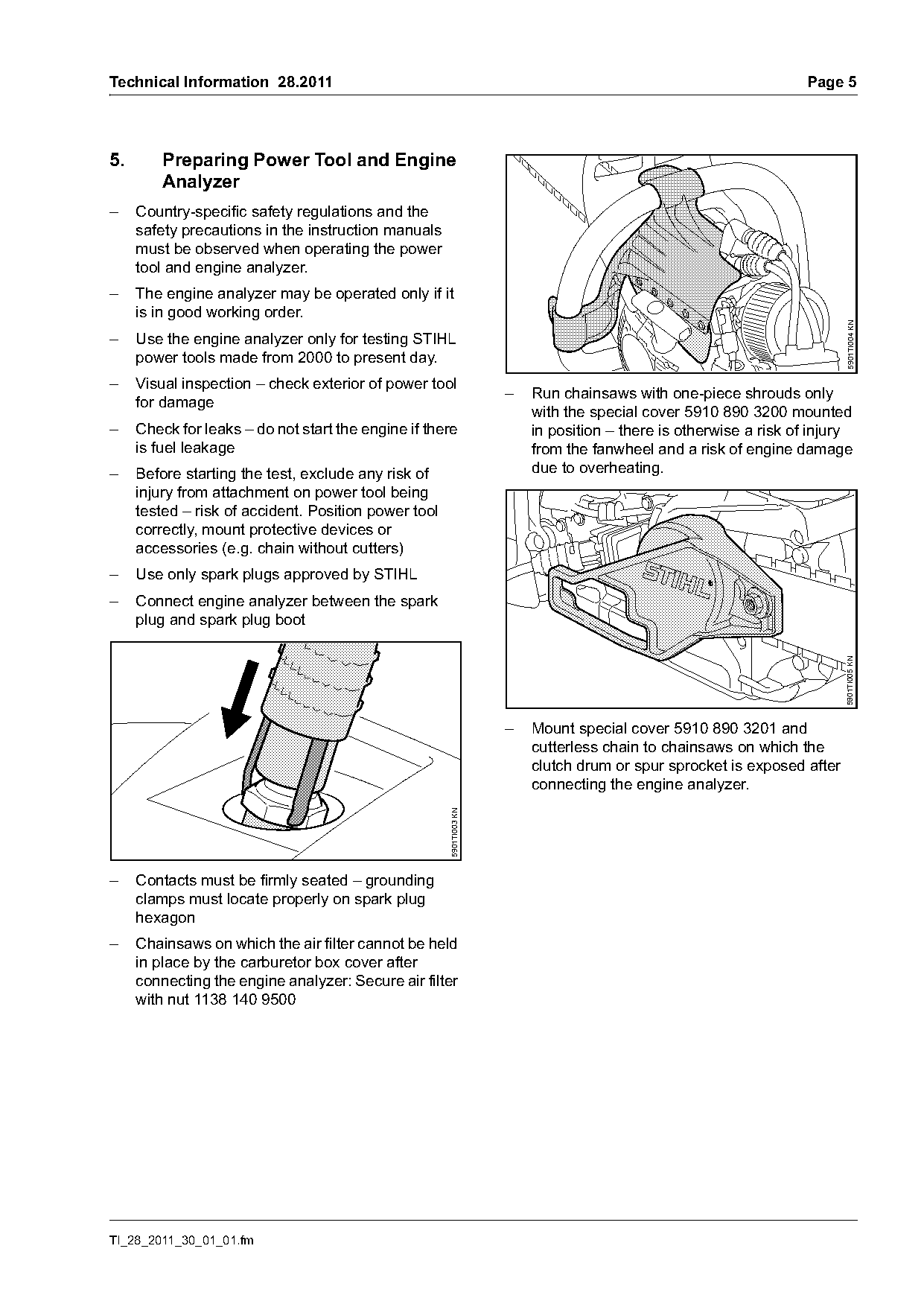
                                                                     –   Run chainsaws with one-piece shrouds only
     for damage
                                                                         with the special cover 5910 890 3200 mounted
–    Check for leaks – do not start the engine if there                  in position – there is otherwise a risk of injury
     is fuel leakage                                                     from the fanwheel and a risk of engine damage
–    Before starting the test, exclude any risk of                       due to overheating.
     injury from attachment on power tool being
     tested – risk of accident. Position power tool
     correctly, mount protective devices or
     accessories (e.g. chain without cutters)
–    Use only spark plugs approved by STIHL
–    Connect engine analyzer between the spark
     plug and spark plug boot

                                                                                                                         5901TI005 KN
                                                                     –   Mount special cover 5910 890 3201 and
                                                                         cutterless chain to chainsaws on which the
                                                                         clutch drum or spur sprocket is exposed after
                                                                         connecting the engine analyzer.
                                                      5901TI003 KN

–    Contacts must be firmly seated – grounding
     clamps must locate properly on spark plug
     hexagon
–    Chainsaws on which the air filter cannot be held
     in place by the carburetor box cover after
     connecting the engine analyzer: Secure air filter
     with nut 1138 140 9500

TI_28_2011_30_01_01.fm
Page 6 of 6
Text of page 6 — search, copy, screen readers
Page 6                                                                                Technical Information 28.2011

6.       STIHL ADG 1                                               7.      Chain Without Cutters
                                                                   Chains without cutters are available as special
                                                                   accessories for service shops.
                                                                   They must be combined with guide bars of the
                                                                   appropriate length. Chains without cutters can also
                                                                   be combined with guide bars with larger grove
                                                                   widths, e.g. 1.3 mm drive link gauge may be used in
                                                                   guide bars with a groove width of 1.5 mm or 1.6 mm.
                                                                   Chains without cutters should be used for diagnostic
                                                                   work and adjustments as well as demonstrations.

                                                    5901TI007 KN

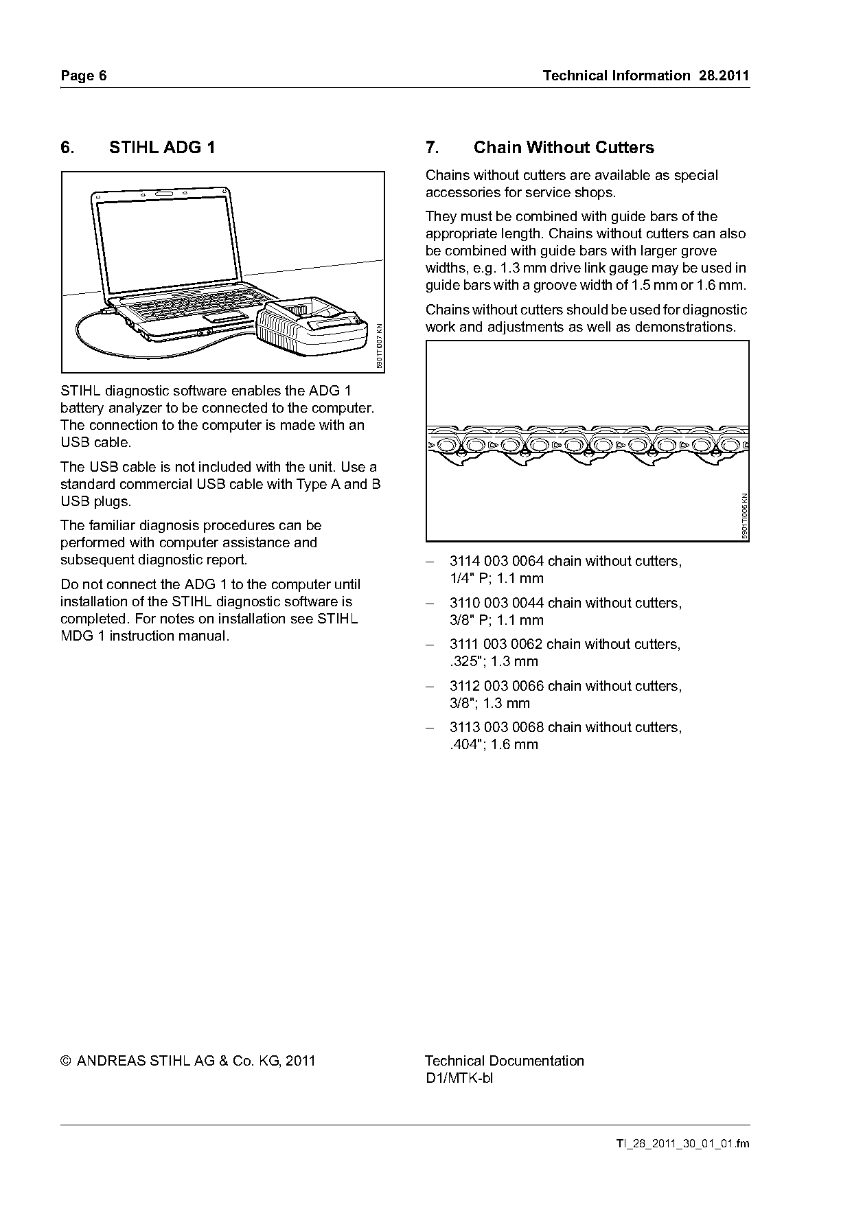
STIHL diagnostic software enables the ADG 1
battery analyzer to be connected to the computer.
The connection to the computer is made with an
USB cable.
The USB cable is not included with the unit. Use a
standard commercial USB cable with Type A and B
USB plugs.

                                                                                                                     5901TI006 KN
The familiar diagnosis procedures can be
performed with computer assistance and
subsequent diagnostic report.                                      –    3114 003 0064 chain without cutters,
Do not connect the ADG 1 to the computer until                          1/4" P; 1.1 mm
installation of the STIHL diagnostic software is                   –    3110 003 0044 chain without cutters,
completed. For notes on installation see STIHL                          3/8" P; 1.1 mm
MDG 1 instruction manual.
                                                                   –    3111 003 0062 chain without cutters,
                                                                        .325"; 1.3 mm
                                                                   –    3112 003 0066 chain without cutters,
                                                                        3/8"; 1.3 mm
                                                                   –    3113 003 0068 chain without cutters,
                                                                        .404"; 1.6 mm

© ANDREAS STIHL AG & Co. KG, 2011                                  Technical Documentation
                                                                   D1/MTK-bl

                                                                                                 TI_28_2011_30_01_01.fm
Most of these PDFs embed fonts with a shifted character map, so the text above was recovered rather than copied — read it as a faithful but imperfect transcription, and treat the page image above each block as the authority where the two disagree — the figures exist only there, because they are vector drawings that text extraction cannot keep.